CN213469164U - Bending machine convenient for fixing parts - Google Patents
Bending machine convenient for fixing parts Download PDFInfo
- Publication number
- CN213469164U CN213469164U CN202022402759.6U CN202022402759U CN213469164U CN 213469164 U CN213469164 U CN 213469164U CN 202022402759 U CN202022402759 U CN 202022402759U CN 213469164 U CN213469164 U CN 213469164U
- Authority
- CN
- China
- Prior art keywords
- plate
- fixedly connected
- pneumatic cylinder
- support
- limiting
- Prior art date
- Legal status (The legal status is an assumption and is not a legal conclusion. Google has not performed a legal analysis and makes no representation as to the accuracy of the status listed.)
- Active
Links
Images


Landscapes
- Bending Of Plates, Rods, And Pipes (AREA)
Abstract
The utility model discloses a convenient fixed part's bender, including workstation and the support of fixed mounting in the workstation top, guiding mechanism is installed to the support upper end, is provided with the horizontal pole in the middle of the support, and the horizontal pole top is provided with the pneumatic cylinder, and the slider is installed to pneumatic cylinder lower extreme both sides, and horizontal pole upper end both sides are provided with the spout, and the pneumatic cylinder passes through slider and spout sliding connection, pneumatic cylinder one side fixedly connected with movable plate, and the pneumatic cylinder bottom is connected with the piston rod, and the piston rod lower extreme passes the horizontal pole in the middle of being connected with and rolls over sword mounting structure: the installation of the bent part is facilitated, because No. two clamp plates are arranged in the middle of the fixing plate, a certain space is reserved for the placement of the lower die, the installation and the replacement of different metal folding knives are facilitated, the bending work efficiency is improved, meanwhile, the scales corresponding to the pointer and the operation box are arranged on one side of the pointer fixedly connected with the upper end of the hydraulic cylinder, the moving distance of the hydraulic cylinder can be accurately controlled, and the bending precision is improved.
Description
Technical Field
The utility model relates to the technical field of machining, specifically be a convenient fixed part's bender.
Background
The bender is the important equipment that the panel beating trade work piece takes shape of bending, its effect is pressed the steel sheet into the part of various shapes according to the technology needs, utilize the mould (general or special mould) of being equipped with to bend into various geometric cross section shape work piece machining device with sheet metal under the cold state, current bender has a mould of going up that pushes down, but the inconvenient change of the mould of current going up, treat simultaneously that the processing part is fixed the back, if will adjust the department of bending of part, then need dismantle the part and fix it again, unusual trouble, also easy error production when reducing work efficiency.
SUMMERY OF THE UTILITY MODEL
An object of the utility model is to provide a make things convenient for fixed part's bender to solve the problem that proposes among the above-mentioned background art.
In order to achieve the above object, the utility model provides a following technical scheme: the utility model provides a convenient fixed part's bender, includes workstation and the support of fixed mounting in the workstation top, guiding mechanism is installed to the support upper end, be provided with the horizontal pole in the middle of the support, the horizontal pole top is provided with the pneumatic cylinder, the slider is installed to pneumatic cylinder lower extreme both sides.
The improved folding knife device is characterized in that sliding grooves are formed in two sides of the upper end of the cross rod, the hydraulic cylinder is connected with the sliding grooves in a sliding mode through sliding blocks, a movable plate is fixedly connected to one side of the hydraulic cylinder, a piston rod is connected to the bottom of the hydraulic cylinder, and the lower end of the piston rod penetrates through the middle of the cross rod and is connected with a folding knife mounting.
The bending machine convenient for fixing parts further comprises a limiting structure.
The adjustment mechanism includes an operating box.
The number of operation boxes sets up one, operation box fixed mounting is in the support upper end.
The improved automatic adjusting device is characterized in that a lead screw is arranged in the operating box, an adjusting nut is connected to the lead screw in a threaded manner, a moving block is fixedly sleeved outside the adjusting nut, guide rails are arranged on two sides of the lead screw and in the operating box, sliding sleeves are connected to two ends of the moving block, the moving block is connected with the guide rails in a sliding manner through the sliding sleeves, a bearing seat connected with one end of the lead screw is arranged in the operating box, and the other end of the lead screw penetrates through the operating box.
The lower end of the moving block is fixedly connected with the upper end of the moving plate.
Through setting up guiding mechanism, rotate the crank, the lead screw rotates, thereby the lead screw rotates and drives adjusting nut and rotate and make the movable block horizontal migration, because movable block bottom and movable plate fixed connection, consequently can drive the department of bending of pneumatic cylinder horizontal migration adjustment part of treating processing, pneumatic cylinder upper end fixed connection's pointer and control box one side are provided with the scale rather than corresponding simultaneously, but the displacement of accurate control pneumatic cylinder improves the precision of bending.
The folding knife mounting structure comprises a right-angle plate.
The number of the right-angle plates is set to be one, the upper ends of the right-angle plates are fixedly connected with the lower end of the piston rod, and the lower ends of the right-angle plates are fixedly connected with two limiting rods.
Two the cover is equipped with the metal on the gag lever post and rolls over the sword, right angle board one end fixed mounting has rubber pad B, the gag lever post is kept away from in rubber pad B one end and is provided with the outer silk of screw thread, the outer silk of screw thread has cup jointed fastening nut.
Through setting up a sword mounting structure, select the metal book sword that corresponds with the bed die for two gag lever posts pass the mounting hole on the metal book sword, the fastening nut on the rotatory screw thread mantle fixes the metal book sword on the gag lever post, make the metal book sword one end support by on the rubber pad B can, made things convenient for the installation of folding the sword to different metals to change, improve the work efficiency of bending.
Preferably, the number of the limiting structures is two, and the two limiting structures are fixedly installed at the upper end of the workbench.
The limiting structure comprises a fixing plate, a first clamping plate, a second clamping plate, a limiting bolt, a rubber pad A and a triangular support base.
Fixed plate bottom and workstation fixed welding, two the one side that the fixed plate is relative is splint and No. two splint of equal fixedly connected with from top to bottom.
All install two spacing bolts on splint, the spacing bolt lower extreme passes splint and fixedly connected with rubber pad A.
Through setting up limit structure, will wait that the part of bending places to the mounting groove inside, rotatory spacing bolt makes the rubber pad A of its bottom tightly support and lean on and treat the part upper surface of bending, can accomplish the fixed of treating the part of bending, has made things convenient for the installation of the part of bending, because No. two splint are established at the middle part of fixed plate, also leave certain space for placing of bed die simultaneously.
Preferably, the upper end of the hydraulic cylinder is fixedly connected with a pointer, and one side of the operating box is provided with scales corresponding to the operating box.
By arranging the corresponding pointer and the corresponding scales, the moving distance of the hydraulic cylinder 6 can be accurately controlled, and the bending precision is improved.
Preferably, reinforcing plates are fixedly welded between two sides of the bottom of the operating box and two sides in the bracket.
The reinforcing plates are fixedly welded between the two sides of the bottom of the operating box and the two sides in the support, so that the stability of connection between the operating box and the support can be improved.
Preferably, two mounting holes for inserting the limiting rods are formed in the metal folding knife, and the aperture of each mounting hole is consistent with the diameter of each limiting rod.
Through being provided with two mounting holes that can supply the gag lever post to alternate, can conveniently install the metal clasp knife on the gag lever post.
Preferably, the lower end of the second clamping plate is fixedly welded with two triangular support bases, and the second clamping plate is fixedly connected with the fixing plate through the two triangular support bases.
Through connecting two triangular supports bases between No. two splint and fixed plate, increase the stability of being connected between No. two splint and the fixed plate.
Compared with the prior art, the beneficial effects of the utility model are that:
1. the utility model discloses in, through setting up limit structure, will treat that the part of bending places to the mounting groove inside, rotatory spacing bolt makes the rubber pad A of its bottom tightly support and lean on and treat the part upper surface of bending, can accomplish the fixed of treating the part of bending, has made things convenient for the installation of the part of bending, because No. two splint are established at the middle part of fixed plate, also leave certain space for placing of bed die simultaneously.
2. The utility model discloses in, through setting up a sword mounting structure, select the metal book sword that corresponds with the bed die for two gag lever posts pass the mounting hole on the metal book sword, fastening nut on the outer silk of rotatory screw is fixed the metal book sword on the gag lever post, make metal book sword one end support lean on the rubber pad B can, made things convenient for the installation change to different metals book sword, improve the work efficiency of bending.
3. The utility model discloses in, through setting up guiding mechanism, rotate the crank, the lead screw rotates, thereby the lead screw rotates and drives adjusting nut and rotate and make movable block horizontal migration, because movable block bottom and movable plate fixed connection, consequently can drive the pneumatic cylinder horizontal migration adjustment and treat the department of bending of processing the part, pneumatic cylinder upper end fixed connection's pointer and control box one side are provided with the scale rather than corresponding simultaneously, but the displacement of accurate control pneumatic cylinder improves the precision of bending.
Drawings
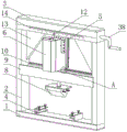
Fig. 1 is a schematic view of the overall structure of the present invention;
fig. 2 is a schematic view of the installation structure of the present invention;
FIG. 3 is a schematic view of an adjusting mechanism of the present invention;
fig. 4 is a schematic diagram of the limiting structure of the present invention;
fig. 5 is an enlarged schematic view of a portion a in fig. 1 according to the present invention.
In the figure: 1. a work table; 2. a support; 3. an adjustment mechanism; 31. an operation box; 32. a screw rod; 33. a moving block; 34. a guide rail; 35. a sliding sleeve; 36. a bearing seat; 37. adjusting the nut; 38. a crank; 4. a limiting structure; 41. a fixing plate; 42. a first clamping plate; 43. a second splint; 44. a limit bolt; 45. a rubber pad A; 46. a triangular support base; 5. moving the plate; 6. a hydraulic cylinder; 7. a piston rod; 8. a folding knife mounting structure; 81. a right-angle plate; 82. a limiting rod; 83. a metal folding knife; 84. fastening a nut; 85. a rubber pad B; 9. a cross bar; 10. a chute; 11. a slider; 12. a pointer; 13. a reinforcing plate; 14. and (4) calibration.
Detailed Description
The present invention will be described in further detail with reference to the accompanying drawings.
For convenience of description, the following description concepts are introduced in the writing of the present invention:
in the present invention 'front', 'rear', 'left', 'right', 'up', 'down' all refer to the orientation in fig. 1, wherein 'front' refers to facing outwards in fig. 1 with respect to the paper surface and 'rear' refers to facing inwards in fig. 1 with respect to the paper surface.
Referring to fig. 1-5, the present invention provides a technical solution: a bending machine convenient for fixing parts comprises a workbench 1 and a support 2 fixedly arranged above the workbench 1, wherein an adjusting mechanism 3 is arranged at the upper end of the support 2, a cross rod 9 is arranged in the middle of the support 2, a hydraulic cylinder 6 is arranged above the cross rod 9, and sliding blocks 11 are arranged on two sides of the lower end of the hydraulic cylinder 6;
the two sides of the upper end of the cross rod 9 are provided with sliding chutes 10, the hydraulic cylinder 6 is connected with the sliding chutes 10 through a sliding block 11 in a sliding manner, one side of the hydraulic cylinder 6 is fixedly connected with a moving plate 5, the bottom of the hydraulic cylinder 6 is connected with a piston rod 7, the lower end of the piston rod 7 penetrates through the middle of the cross rod 9 and is connected with a folding knife mounting structure 8,
the bending machine convenient for fixing parts further comprises a limiting structure 4;
the adjusting mechanism 3 includes an operation box 31;
one operation box 31 is arranged, and the operation box 31 is fixedly arranged at the upper end of the bracket 2;
a screw rod 32 is arranged in the operation box 31, an adjusting nut 37 is connected to the screw rod 32 in a threaded manner, a moving block 33 is fixedly sleeved outside the adjusting nut 37, guide rails 34 are arranged on two sides of the screw rod 32 and in the operation box 31, sliding sleeves 35 are connected to two ends of the moving block 33, the moving block 33 is connected with the guide rails 34 in a sliding manner through the sliding sleeves 35, a bearing seat 36 connected with one end of the screw rod 32 is arranged in the operation box 31, and the other end of the screw rod 32 penetrates through the operation box 31 to be connected with a crank 38;
the lower end of the moving block 33 is fixedly connected with the upper end of the moving plate 5;
the folding knife mounting structure 8 comprises a right-angle plate 81;
one right-angle plate 81 is arranged in quantity, the upper end of the right-angle plate is fixedly connected with the lower end of the piston rod 7, and the lower end of the right-angle plate 81 is fixedly connected with two limiting rods 82;
two the cover is equipped with metal folding knife 83 on the gag lever post 82, right angle board 81 one end fixed mounting has rubber pad B85, gag lever post 82 is kept away from rubber pad B85 one end and is provided with the outer silk of screw thread, the outer silk of screw thread has cup jointed fastening nut 84.
Furthermore, the number of the limiting structures 4 is two, and the two limiting structures 4 are fixedly installed at the upper end of the workbench 1;
the limiting structure 4 comprises a fixing plate 41, a first clamping plate 42, a second clamping plate 43, a limiting bolt 44, a rubber pad A45 and a triangular support base 46;
the bottom of each fixing plate 41 is fixedly welded with the workbench 1, one surface, opposite to each fixing plate 41, of each fixing plate is fixedly connected with a first clamping plate 42 and a second clamping plate 43 from top to bottom, and the second clamping plates 43 are arranged in the middle of the fixing plates 41;
all install two spacing bolts 44 on splint 42, the spacing bolt 44 lower extreme passes splint 42 and fixedly connected with rubber pad A45.
Furthermore, the upper end of the hydraulic cylinder 6 is fixedly connected with a pointer 12, and one side of the operation box 31 is provided with a scale 14 corresponding to the pointer.
Furthermore, reinforcing plates 13 are fixedly welded between two sides of the bottom of the operation box 31 and two sides in the bracket 2.
Further, two mounting holes for inserting the limiting rod 82 are formed in the metal folding knife 83, and the diameter of each mounting hole is consistent with that of the limiting rod 82.
Further, No. two splint 43 lower extreme fixed welding have two triangular supports base 46, No. two splint 43 pass through two triangular supports base 46 and fixed plate 41 fixed connection
The utility model discloses the operating principle who prescribes a limit to make things convenient for fixed part's bender as follows:
limit structure: as can be seen from fig. 1 and 4, a mounting groove for a part to be bent is formed between the first clamping plate 42 and the second clamping plate 43, a lower die (not shown) matched with the folding knife 8 is arranged at the bottom of the mounting groove, the part to be bent is placed in the mounting groove, the rubber pad a45 at the bottom of the limiting bolt 44 is rotated to tightly abut against the upper surface of the part to be bent, the part to be bent can be fixed, the part to be bent is convenient to mount, and a certain space is reserved for placing the lower die due to the fact that the second clamping plate 43 is arranged in the middle of the fixing plate 41.
Folding knife mounting structure: the metal folding knife 83 corresponding to the lower die is selected, so that the two limiting rods 82 penetrate through mounting holes in the metal folding knife 83, the fastening nut 84 on the outer thread of the rotary thread fixes the metal folding knife 83 on the limiting rods 82, and one end of the metal folding knife 83 abuts against the rubber pad B85, so that the mounting and the replacement of different metal folding knives 83 are facilitated, and the bending work efficiency is improved.
An adjusting mechanism: the crank 38 is rotated, the screw rod 32 rotates to drive the adjusting nut 37 to rotate, so that the moving block 33 moves horizontally, the bottom of the moving block 33 is fixedly connected with the moving plate 5, the hydraulic cylinder 6 can be driven to move horizontally to adjust the bending position of the part to be machined, and meanwhile, the scales 14 corresponding to the pointer 12 and the operation box 31 which are fixedly connected with the upper end of the hydraulic cylinder 6 are arranged on one side, so that the moving distance of the hydraulic cylinder 6 can be accurately controlled, and the bending precision is improved.
The hydraulic cylinder 6 is started, the subsequent operation process of the hydraulic cylinder 6 is common knowledge, so that the subsequent operation process is not described too much, and the piston rod 7 descends to drive the metal folding knife 83 to descend to bend the fixed part to be processed.
The utility model discloses a control mode comes automatic control through the controller, and the control circuit of controller can realize through the simple programming of technical staff in this field, and the supply also belongs to the common general knowledge in this field, and the utility model discloses mainly used protects mechanical device, so the utility model discloses no longer explain control mode and circuit connection in detail.
Finally, although the present invention has been described in detail with reference to the preferred embodiments, it should be understood by those skilled in the art that the present invention can be modified or replaced by other means without departing from the spirit and scope of the present invention, which should be construed as limited only by the appended claims.
Claims (6)
1. A bending machine convenient for fixing parts comprises a workbench (1) and a support (2) fixedly installed above the workbench (1), wherein an adjusting mechanism (3) is installed at the upper end of the support (2), a cross rod (9) is arranged in the middle of the support (2), a hydraulic cylinder (6) is arranged above the cross rod (9), and sliding blocks (11) are installed on two sides of the lower end of the hydraulic cylinder (6);
horizontal pole (9) upper end both sides are provided with spout (10), pneumatic cylinder (6) are through slider (11) and spout (10) sliding connection, pneumatic cylinder (6) one side fixedly connected with movable plate (5), pneumatic cylinder (6) bottom is connected with piston rod (7), piston rod (7) lower extreme passes horizontal pole (9) intermediate junction and has a sword mounting structure (8), its characterized in that: the device also comprises a limiting structure (4);
the adjusting mechanism (3) comprises an operation box (31);
one operation box (31) is arranged, and the operation boxes (31) are fixedly arranged at the upper end of the bracket (2);
a screw rod (32) is arranged in the operation box (31), an adjusting nut (37) is connected to the screw rod (32) in a threaded manner, a moving block (33) is fixedly sleeved outside the adjusting nut (37), guide rails (34) are arranged on two sides of the screw rod (32) and in the operation box (31), two ends of the moving block (33) are connected with sliding sleeves (35), the moving block (33) is connected with the guide rails (34) in a sliding manner through the sliding sleeves (35), a bearing seat (36) connected with one end of the screw rod (32) is arranged in the operation box (31), and the other end of the screw rod (32) penetrates through the operation box (31) and is connected with a crank (38);
the lower end of the moving block (33) is fixedly connected with the upper end of the moving plate (5);
the folding knife mounting structure (8) comprises a right-angle plate (81);
one right-angle plate (81) is arranged, the upper end of the right-angle plate is fixedly connected with the lower end of the piston rod (7), and the lower end of the right-angle plate (81) is fixedly connected with two limiting rods (82);
two be equipped with metal folding knife (83) on gag lever post (82), right angle board (81) one end fixed mounting has rubber pad B (85), gag lever post (82) are kept away from rubber pad B (85) one end and are provided with the outer silk of screw thread, fastening nut (84) has been cup jointed on the outer silk of screw thread.
2. The bending machine convenient for fixing parts according to claim 1, is characterized in that: the number of the limiting structures (4) is two, and the two limiting structures (4) are fixedly arranged at the upper end of the workbench (1);
the limiting structure (4) comprises a fixing plate (41), a first clamping plate (42), a second clamping plate (43), a limiting bolt (44), a rubber pad A (45) and a triangular support base (46);
the bottom of each fixing plate (41) is fixedly welded with the workbench (1), and one surface, opposite to each fixing plate (41), is fixedly connected with a first clamping plate (42) and a second clamping plate (43) from top to bottom;
all install two spacing bolts (44) on splint (42), a splint (42) and fixedly connected with rubber pad A (45) are passed to spacing bolt (44) lower extreme.
3. The bending machine convenient for fixing parts according to claim 1, is characterized in that: the upper end of the hydraulic cylinder (6) is fixedly connected with a pointer (12), and one side of the operating box (31) is provided with scales (14) corresponding to the operating box.
4. The bending machine convenient for fixing parts according to claim 1, is characterized in that: reinforcing plates (13) are fixedly welded between two sides of the bottom of the operating box (31) and two sides in the support (2).
5. The bending machine convenient for fixing parts according to claim 1, is characterized in that: two mounting holes for inserting the limiting rods (82) are formed in the metal folding knife (83), and the diameter of each mounting hole is consistent with that of each limiting rod (82).
6. The bending machine convenient for fixing parts according to claim 2, is characterized in that: no. two splint (43) lower extreme fixed welding have two triangular supports base (46), No. two splint (43) are through two triangular supports base (46) and fixed plate (41) fixed connection.
Priority Applications (1)
| Application Number | Priority Date | Filing Date | Title |
|---|---|---|---|
| CN202022402759.6U CN213469164U (en) | 2020-10-26 | 2020-10-26 | Bending machine convenient for fixing parts |
Applications Claiming Priority (1)
| Application Number | Priority Date | Filing Date | Title |
|---|---|---|---|
| CN202022402759.6U CN213469164U (en) | 2020-10-26 | 2020-10-26 | Bending machine convenient for fixing parts |
Publications (1)
| Publication Number | Publication Date |
|---|---|
| CN213469164U true CN213469164U (en) | 2021-06-18 |
Family
ID=76369486
Family Applications (1)
| Application Number | Title | Priority Date | Filing Date |
|---|---|---|---|
| CN202022402759.6U Active CN213469164U (en) | 2020-10-26 | 2020-10-26 | Bending machine convenient for fixing parts |
Country Status (1)
| Country | Link |
|---|---|
| CN (1) | CN213469164U (en) |
-
2020
- 2020-10-26 CN CN202022402759.6U patent/CN213469164U/en active Active
Similar Documents
| Publication | Publication Date | Title |
|---|---|---|
| CN110315204A (en) | Double-station list laser lens multistage welding equipment | |
| CN209020988U (en) | A kind of small-sized bending machine | |
| CN106364889B (en) | The bent axle feed mechanism of compressor crank shaft riveting press equipment | |
| CN213469164U (en) | Bending machine convenient for fixing parts | |
| CN209035271U (en) | A kind of mold auxiliary locator | |
| CN112536495B (en) | Tin soldering machine | |
| CN209222990U (en) | A kind of numerical control press | |
| CN209318492U (en) | A kind of bending machine | |
| CN208357998U (en) | A kind of welding gun holding device of motor stator argon welding machine | |
| CN112024652A (en) | Drum-shaped trimming multipoint compensation mechanism of numerical control bending machine | |
| CN219335473U (en) | Bender loading attachment | |
| CN221754547U (en) | Filing cabinet bender loading attachment | |
| CN219112567U (en) | Auxiliary positioning device for bending machine | |
| CN221210159U (en) | Anti-offset device of high-precision slow wire cutting machine | |
| CN212551183U (en) | Flat pipe coiler | |
| CN108160845B (en) | Bend pipe automatic charging machine | |
| CN218169322U (en) | Flower comb assembly quality | |
| CN216801469U (en) | Car seat skeleton bending device with direction function | |
| CN109013765A (en) | A kind of small-sized bending machine | |
| CN219211169U (en) | Bending device for hardware plate | |
| CN212192251U (en) | Adjustable machining positioning device | |
| CN220613685U (en) | Automatic material lifting jig | |
| CN108903158A (en) | A kind of Che Zhuji | |
| CN220515096U (en) | Bending machine convenient for replacing die | |
| CN219664804U (en) | Automatic cabinet body panel beating bending device of location |
Legal Events
| Date | Code | Title | Description |
|---|---|---|---|
| GR01 | Patent grant | ||
| GR01 | Patent grant |