CN213461667U - Photovoltaic power generation controller - Google Patents
Photovoltaic power generation controller Download PDFInfo
- Publication number
- CN213461667U CN213461667U CN202023014588.6U CN202023014588U CN213461667U CN 213461667 U CN213461667 U CN 213461667U CN 202023014588 U CN202023014588 U CN 202023014588U CN 213461667 U CN213461667 U CN 213461667U
- Authority
- CN
- China
- Prior art keywords
- controller body
- controller
- power generation
- photovoltaic power
- fan box
- Prior art date
- Legal status (The legal status is an assumption and is not a legal conclusion. Google has not performed a legal analysis and makes no representation as to the accuracy of the status listed.)
- Active
Links
Images


Classifications
-
- Y—GENERAL TAGGING OF NEW TECHNOLOGICAL DEVELOPMENTS; GENERAL TAGGING OF CROSS-SECTIONAL TECHNOLOGIES SPANNING OVER SEVERAL SECTIONS OF THE IPC; TECHNICAL SUBJECTS COVERED BY FORMER USPC CROSS-REFERENCE ART COLLECTIONS [XRACs] AND DIGESTS
- Y02—TECHNOLOGIES OR APPLICATIONS FOR MITIGATION OR ADAPTATION AGAINST CLIMATE CHANGE
- Y02E—REDUCTION OF GREENHOUSE GAS [GHG] EMISSIONS, RELATED TO ENERGY GENERATION, TRANSMISSION OR DISTRIBUTION
- Y02E10/00—Energy generation through renewable energy sources
- Y02E10/50—Photovoltaic [PV] energy
- Y02E10/56—Power conversion systems, e.g. maximum power point trackers
Abstract
The utility model discloses a photovoltaic power generation controller, which comprises a controller body, wherein the bottom of the controller body is provided with a base, the top of the controller body is provided with a mounting plate, the top of the mounting plate is provided with a mounting groove and a water guide plate, the mounting groove is symmetrically arranged on two sides of the mounting plate, a motor is arranged in the mounting groove, the output end of the bottom of the motor is provided with a screw rod, the two sides of the top of the base are symmetrically provided with a sleeve pipe, the sleeve pipe is sleeved outside the screw rod, the sleeve pipe is in threaded connection with the screw rod, the rear side of the controller body is provided with a fan box, through holes corresponding to the fan box are arranged in the controller body in an array manner, the utility model has simple structure and reasonable design, can radiate the controller body and has certain sun-shading and rain-shielding effects, and the controller, the controller body is not easily affected by rainwater on the ground.
Description
Technical Field
The utility model relates to a photovoltaic power generation controller belongs to photovoltaic power generation technical field.
Background
Photovoltaic power generation is according to the photovoltaic effect principle, utilize solar cell to directly convert solar energy into electric energy, photovoltaic power generation controller is arranged in solar power generation system, the automatic control equipment that control multichannel solar cell square matrix charges the battery and the battery supplies power for solar inverter load, the controller often can be placed in the open air, need can carry out the sunshade to it and keep off the rain, guarantee its radiating effect, and when the rainfall is great, need make the controller rise, make subaerial rainwater be difficult for causing the influence to the controller, for this reason, a photovoltaic power generation controller is provided.
SUMMERY OF THE UTILITY MODEL
An object of the utility model is to provide a photovoltaic power generation controller to solve the problem that proposes in the above-mentioned background art.
In order to achieve the above object, the utility model provides a following technical scheme:
a photovoltaic power generation controller comprises a controller body, wherein a base is arranged at the bottom of the controller body, the top of the controller body is provided with a mounting plate, the top of the mounting plate is provided with a mounting groove and a water guide plate, the mounting grooves are symmetrically arranged at two sides of the mounting plate, the motor is arranged in the mounting groove, the screw rod is arranged at the output end of the bottom of the motor, the sleeves are symmetrically arranged at two sides of the top of the base, the sleeves are sleeved at the outer sides of the screw rod, the sleeve is in threaded connection with the screw, the rear side of the controller body is provided with a fan box, through holes corresponding to the fan box are arranged in the controller body in an array mode, a fan is arranged in the fan box, square frame plates are arranged on the periphery of the outer side of the fan box, and the four corners of the rear side of the square frame plate are provided with first bolts, and the tail ends of the first bolts penetrate through the square frame plate and are in threaded connection with the controller body.
Furthermore, the top of the water guide plate is provided with a water guide groove inclined towards two sides.
Furthermore, a dust screen is arranged on the rear side of the fan box, second bolts are arranged at four corners of the rear side of the dust screen, and tail ends of the second bolts penetrate through the dust screen and are in threaded connection with the fan box.
Further, a gap is reserved between the sleeve and the controller body.
Furthermore, the mounting plate bilateral symmetry is provided with the spread groove.
Furthermore, a connecting plate is arranged in the connecting groove and fixedly connected with the water guide plate, third bolts are symmetrically arranged on one side of the connecting plate, and the tail ends of the third bolts penetrate through the connecting plate and are in threaded connection with the mounting plate.
The utility model has the advantages that:
1. through the fan, can dispel the heat to the controller body, through the water deflector, have certain sunshade effect of keeping off the rain, through screw rod and sleeve pipe, make the controller body go up and down, make subaerial rainwater be difficult for causing the influence to the controller body.
2. Through setting up the guiding gutter, can be better lead the rainwater to the guiding board both sides, through setting up the dust screen, make the dust be difficult for getting into this internal through fan case controller, make and leave the clearance between sleeve pipe and the controller body, when controller body goes up and down, can not receive the sleeve pipe influence, through setting up spread groove and connecting plate, can install the dismantlement between guiding board and the mounting panel.
Drawings
The accompanying drawings are included to provide a further understanding of the invention, and are incorporated in and constitute a part of this specification, illustrate embodiments of the invention, and together with the description serve to explain the invention and not to limit the invention.
Fig. 1 is a schematic diagram of an internal structure of a photovoltaic power generation controller according to the present invention;
fig. 2 is a right side sectional view of a controller body of a photovoltaic power generation controller according to the present invention;
fig. 3 is a schematic view of a water deflector of a photovoltaic power generation controller according to the present invention;
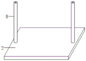
fig. 4 is a schematic diagram of a bushing of a photovoltaic power generation controller according to the present invention;
reference numbers in the figures: 1. a controller body; 2. a base; 3. mounting a plate; 4. mounting grooves; 5. a water guide plate; 6. a motor; 7. a screw; 8. a sleeve; 9. a fan case; 10. a through hole; 11. a fan; 12. a square frame plate; 13. a first bolt; 14. a water chute; 15. a dust screen; 16. a second bolt; 17. connecting grooves; 18. a connecting plate; 19. and a third bolt.
Detailed Description
The preferred embodiments of the present invention will be described in conjunction with the accompanying drawings, and it will be understood that they are presented herein only to illustrate and explain the present invention, and not to limit the present invention.
Referring to fig. 1-4, the present invention provides a technical solution: a photovoltaic power generation controller comprises a controller body 1, wherein a base 2 is arranged at the bottom of the controller body 1, a mounting plate 3 is arranged at the top of the controller body 1, a mounting groove 4 and a water guide plate 5 are arranged at the top of the mounting plate 3, the mounting groove 4 is symmetrically arranged at two sides of the mounting plate 3, a motor 6 is arranged in the mounting groove 4, a screw 7 is arranged at the output end of the bottom of the motor 6, sleeves 8 are symmetrically arranged at two sides of the top of the base 2, a gap is reserved between each sleeve 8 and the controller body 1, each sleeve 8 is sleeved outside each screw 7, each sleeve 8 is in threaded connection with each screw 7, a fan box 9 is arranged at the rear side of the controller body 1, through holes 10 corresponding to the fan boxes 9 are arranged in the controller body 1 in an array mode, a fan 11 is arranged in each fan box 9, and square frame plates 12 are, and the four corners of the rear side of the square frame plate 12 are provided with first bolts 13, and the tail ends of the first bolts 13 penetrate through the square frame plate 12 and are in threaded connection with the controller body 1.
Specifically, as shown in fig. 3, the top of the water guide plate 5 is provided with a water guide groove 14 inclined to two sides, so as to better guide rainwater to two sides of the water guide plate 5.
Specifically, as shown in fig. 2, a dust screen 15 is arranged on the rear side of the fan case 9, second bolts 16 are arranged at four corners of the rear side of the dust screen 15, and the tail ends of the second bolts 16 penetrate through the dust screen 15 and are in threaded connection with the fan case 9, so that dust is not easy to enter the controller body 1 through the fan case 9.
Specifically, as shown in fig. 1 and 3, mounting panel 3 bilateral symmetry is provided with spread groove 17, be provided with connecting plate 18 in the spread groove 17, connecting plate 18 and water deflector 5 fixed connection, connecting plate 18 bilateral symmetry is provided with third bolt 19, just third bolt 19 tail end runs through connecting plate 18 and mounting panel 3 threaded connection, can install the dismantlement between water deflector 5 and the mounting panel 3.
The utility model discloses the theory of operation: supply power for motor 6 and fan 11 through external power supply, when rainy day, through water deflector 5, can be to carrying out the sunshade rain for controller body 1, and through guiding gutter 14, better lead the rainwater to 5 both sides of water deflector, when the rainfall is great, open motor 6, make screw rod 7 rotate, sleeve pipe 8 through base 2 top, make controller body 1 rise, make subaerial rainwater be difficult for leading to the fact the influence to controller body 1, and open fan 11, can dispel the heat to controller body 1 through-hole 10, make and leave the clearance between sleeve pipe 8 and the controller body 1, when controller body 1 rises, can not receive the influence of sleeve pipe 8.
The above is the preferred embodiment of the present invention, and the technical personnel in the field of the present invention can also change and modify the above embodiment, therefore, the present invention is not limited to the above specific embodiment, and any obvious improvement, replacement or modification made by the technical personnel in the field on the basis of the present invention all belong to the protection scope of the present invention.
Claims (6)
1. A photovoltaic power generation controller, includes controller body (1), its characterized in that: the controller is characterized in that a base (2) is arranged at the bottom of the controller body (1), a mounting plate (3) is arranged at the top of the controller body (1), a mounting groove (4) and a water guide plate (5) are arranged at the top of the mounting plate (3), the mounting groove (4) is symmetrically arranged at two sides of the mounting plate (3), a motor (6) is arranged in the mounting groove (4), a screw rod (7) is arranged at the output end of the bottom of the motor (6), sleeves (8) are symmetrically arranged at two sides of the top of the base (2), the sleeves (8) are sleeved outside the screw rod (7), the sleeves (8) are in threaded connection with the screw rod (7), a fan box (9) is arranged at the rear side of the controller body (1), through holes (10) corresponding to the fan box (9) are formed in the controller body (1) in an array mode, and a, the fan box is characterized in that square frame plates (12) are arranged on the periphery of the outer side of the fan box (9), first bolts (13) are arranged at four corners of the rear side of each square frame plate (12), and the tail ends of the first bolts (13) penetrate through the square frame plates (12) to be in threaded connection with the controller body (1).
2. A photovoltaic power generation controller in accordance with claim 1, wherein: the top of the water guide plate (5) is provided with a water guide groove (14) inclined towards two sides.
3. A photovoltaic power generation controller in accordance with claim 1, wherein: the fan box is characterized in that a dustproof net (15) is arranged on the rear side of the fan box (9), second bolts (16) are arranged at four corners of the rear side of the dustproof net (15), and the tail ends of the second bolts (16) penetrate through the dustproof net (15) and are in threaded connection with the fan box (9).
4. A photovoltaic power generation controller in accordance with claim 1, wherein: and a gap is reserved between the sleeve (8) and the controller body (1).
5. A photovoltaic power generation controller in accordance with claim 1, wherein: the mounting plate (3) bilateral symmetry is provided with spread groove (17).
6. A photovoltaic power generation controller in accordance with claim 5, wherein: the connecting structure is characterized in that a connecting plate (18) is arranged in the connecting groove (17), the connecting plate (18) is fixedly connected with the water guide plate (5), third bolts (19) are symmetrically arranged on one side of the connecting plate (18), and the tail ends of the third bolts (19) penetrate through the connecting plate (18) and are in threaded connection with the mounting plate (3).
Priority Applications (1)
| Application Number | Priority Date | Filing Date | Title |
|---|---|---|---|
| CN202023014588.6U CN213461667U (en) | 2020-12-15 | 2020-12-15 | Photovoltaic power generation controller |
Applications Claiming Priority (1)
| Application Number | Priority Date | Filing Date | Title |
|---|---|---|---|
| CN202023014588.6U CN213461667U (en) | 2020-12-15 | 2020-12-15 | Photovoltaic power generation controller |
Publications (1)
| Publication Number | Publication Date |
|---|---|
| CN213461667U true CN213461667U (en) | 2021-06-15 |
Family
ID=76305470
Family Applications (1)
| Application Number | Title | Priority Date | Filing Date |
|---|---|---|---|
| CN202023014588.6U Active CN213461667U (en) | 2020-12-15 | 2020-12-15 | Photovoltaic power generation controller |
Country Status (1)
| Country | Link |
|---|---|
| CN (1) | CN213461667U (en) |
-
2020
- 2020-12-15 CN CN202023014588.6U patent/CN213461667U/en active Active
Similar Documents
| Publication | Publication Date | Title |
|---|---|---|
| CN213461667U (en) | Photovoltaic power generation controller | |
| CN214542971U (en) | Dustproof electric power cabinet of outdoor low pressure | |
| CN108429222B (en) | Outdoor high-voltage cable distribution box | |
| CN212935336U (en) | Heat abstractor for block terminal | |
| CN201722853U (en) | Ceramic tile suitable for building integrated photovoltaic | |
| CN211655529U (en) | Energy-concerving and environment-protective type switch board | |
| CN210629417U (en) | Photovoltaic module with good heat dissipation performance | |
| CN203423839U (en) | Electronic ballast shell structure | |
| CN210577321U (en) | Special electric energy optimization box for photovoltaic power station | |
| CN219499828U (en) | Electromechanical device heat abstractor for highway | |
| CN219812130U (en) | Photovoltaic junction box capable of improving heat dissipation efficiency of diode bin | |
| CN219874610U (en) | Medium-voltage switch cabinet for realizing equipment interlocking integration | |
| CN210297041U (en) | Box-type substation | |
| CN219779739U (en) | A pin-connected panel inlet wire case for bus duct | |
| CN210984743U (en) | Photovoltaic module with good heat dissipation performance | |
| CN211981833U (en) | Photovoltaic array fault diagnosis monitoring box | |
| CN212086222U (en) | Wireless network bridge for communication engineering | |
| CN214798232U (en) | Novel environmental protection low pressure power distribution box | |
| CN213584789U (en) | Outdoor comprehensive distribution box | |
| CN214001398U (en) | Bidirectional control charging control terminal | |
| CN216491736U (en) | MPPT's complementary controller of scene | |
| CN220628683U (en) | Distributed photovoltaic power generation system | |
| CN209993975U (en) | Outdoor distribution box structure | |
| CN216436538U (en) | Protection device convenient for power system information equipment | |
| CN218153949U (en) | High-efficient photovoltaic power generation LED wisdom street lamp of integration |
Legal Events
| Date | Code | Title | Description |
|---|---|---|---|
| GR01 | Patent grant | ||
| GR01 | Patent grant |