CN209993975U - An outdoor distribution box structure - Google Patents
An outdoor distribution box structure Download PDFInfo
- Publication number
- CN209993975U CN209993975U CN201921307266.5U CN201921307266U CN209993975U CN 209993975 U CN209993975 U CN 209993975U CN 201921307266 U CN201921307266 U CN 201921307266U CN 209993975 U CN209993975 U CN 209993975U
- Authority
- CN
- China
- Prior art keywords
- distribution box
- box
- power distribution
- fixed
- heat dissipation
- Prior art date
- Legal status (The legal status is an assumption and is not a legal conclusion. Google has not performed a legal analysis and makes no representation as to the accuracy of the status listed.)
- Expired - Fee Related
Links
Images


Landscapes
- Photovoltaic Devices (AREA)
Abstract
本实用新型涉及一种室外配电箱结构,包括底座,所述底座顶部固定设有散热箱,所述散热箱顶部固定设有配电箱体,所述配电箱体顶部固定设有顶板,所述顶板顶部固定设有太阳能电池板,所述配电箱体内腔后侧固定设有电气安装板,太阳能电池板可以把太阳能转化为电能,蓄电池可以对太阳能电池板转化的电能进行储存,蓄电池可以对散热扇进行供电,通过设置电气安装板可以对电气元件进行安装,通过设置散热扇可以对配电箱体内腔的电气元件进行吹风散热,可以防止电气元件因温度过高而损坏,通过设置上散热槽与下散热槽方便对配电箱体内腔进行散热,上散热槽的高度高于下散热槽的高度可以防止雨水进入配电箱体内腔,防水性能好。
The utility model relates to an outdoor power distribution box structure, comprising a base, a heat dissipation box is fixedly arranged on the top of the base, a power distribution box body is fixedly arranged on the top of the heat dissipation box, and a top plate is fixedly arranged on the top of the power distribution box body. A solar panel is fixed on the top of the top plate, and an electrical installation panel is fixed on the back side of the inner cavity of the power distribution box. The solar panel can convert solar energy into electrical energy, and the battery can store the electrical energy converted by the solar panel. The cooling fan can be powered, and the electrical components can be installed by setting the electrical installation board. The upper heat sink and the lower heat sink are convenient to dissipate heat in the inner cavity of the distribution box. The height of the upper heat sink is higher than the height of the lower heat sink to prevent rainwater from entering the cavity of the distribution box, and has good waterproof performance.
Description
技术领域technical field
本实用新型涉及一种室外配电箱结构,属于配电箱技术领域。The utility model relates to an outdoor distribution box structure, which belongs to the technical field of distribution boxes.
背景技术Background technique
配电箱中设置有很多的控制元器件与线路,在工作的工程中,电器柜中的控制元器件会发出较大的热量,如果热量不及时散发出去,电器柜中的温度上升会造成控制系统的失灵,这不仅会使得设备无法正常运转,而且会带来较大的安全隐患,现有的配电箱一般通过在配电箱外壳开口,通过自然的空气流动为配电箱内部电器件进行降温,但是作为室外配电箱,当天气恶劣时,往往会通过配电箱外壳的开口进入雨水,对配电箱内的电器件造成损坏,因此需要进一步改进。There are many control components and circuits in the distribution box. In the work project, the control components in the electrical cabinet will emit a large amount of heat. If the heat is not dissipated in time, the temperature rise in the electrical cabinet will cause control. The failure of the system will not only make the equipment unable to operate normally, but also bring about a greater safety hazard. The existing distribution box generally provides electrical components inside the distribution box through natural air flow through the opening of the distribution box shell. To cool down, but as an outdoor distribution box, when the weather is bad, rainwater often enters through the opening of the distribution box shell, causing damage to the electrical components in the distribution box, so further improvement is required.
实用新型内容Utility model content
本实用新型要解决的技术问题克服现有的缺陷,提供一种室外配电箱结构,散热性能好,防水性能好,太阳能电池板可以把太阳能转化为电能,蓄电池可以对太阳能电池板转化的电能进行储存,蓄电池可以对散热扇进行供电,通过设置电气安装板可以对电气元件进行安装,通过设置散热扇可以对配电箱体内腔的电气元件进行吹风散热,可以防止电气元件因温度过高而损坏,通过设置上散热槽与下散热槽方便对配电箱体内腔进行散热,上散热槽的高度高于下散热槽的高度可以防止雨水进入配电箱体内腔,防水性能好,内箱体与外箱体之间通过弹簧柱连接可以提高内箱体的减震性能,可以防止配电箱体内腔的电气元件受外界因素影响而剧烈震动,可以有效解决背景技术中的问题。The technical problem to be solved by the utility model overcomes the existing defects, and provides an outdoor distribution box structure, which has good heat dissipation performance and good waterproof performance. For storage, the battery can supply power to the cooling fan, and the electrical components can be installed by setting the electrical installation board. If it is damaged, it is convenient to dissipate heat in the inner cavity of the power distribution box by setting the upper heat dissipation groove and the lower heat dissipation groove. The height of the upper heat dissipation groove is higher than the height of the lower heat dissipation groove to prevent rainwater from entering the inner cavity of the power distribution box. The connection with the outer box through the spring column can improve the shock absorption performance of the inner box, can prevent the electrical components in the inner cavity of the power distribution box from vibrating violently due to external factors, and can effectively solve the problems in the background art.
为了解决上述技术问题,本实用新型提供了如下的技术方案:In order to solve the above-mentioned technical problems, the utility model provides the following technical solutions:
一种室外配电箱结构,包括底座,所述底座顶部固定设有散热箱,所述散热箱顶部固定设有配电箱体,所述配电箱体顶部固定设有顶板,所述顶板顶部固定设有太阳能电池板,所述配电箱体内腔后侧固定设有电气安装板,所述电气安装板顶部前侧表面固定设有蓄电池,所述配电箱体包括内箱体,所述内箱体外侧通过弹簧柱连接有外箱体,所述内箱体顶部两侧等距对称设有上散热槽,所述外箱体底部两侧对称等距设有下散热槽,所述配电箱体内腔底部固定设有散热扇,所述太阳能电池板、蓄电池、散热扇之间通过导线依次连接。An outdoor power distribution box structure includes a base, a heat dissipation box is fixed on the top of the base, a power distribution box is fixed on the top of the heat dissipation box, a top plate is fixed on the top of the power distribution box, and the top of the top plate is fixed A solar panel is fixed, an electrical installation board is fixed on the rear side of the inner cavity of the power distribution box, a battery is fixed on the front surface of the top of the electrical installation board, and the power distribution box includes an inner box. The outer side of the inner box is connected to the outer box by spring columns, the upper heat dissipation grooves are symmetrically arranged on both sides of the top of the inner box, and the lower heat dissipation grooves are symmetrically and equally spaced on both sides of the bottom of the outer box. A cooling fan is fixed at the bottom of the inner cavity of the electric box, and the solar panel, the storage battery, and the cooling fan are connected in sequence through wires.
进一步而言,所述配电箱体内腔底部挖设有吹风口,所述吹风口内腔固定设有灰尘过滤网。Further, an air outlet is dug at the bottom of the inner cavity of the power distribution box, and a dust filter is fixed in the inner cavity of the air outlet.
进一步而言,所述散热箱上等距挖设有进气口。Further, air inlets are dug equidistantly on the heat dissipation box.
进一步而言,所述底座上位于其四角处对称挖设有固定孔。Further, fixing holes are symmetrically dug at four corners of the base.
进一步而言,所述配电箱体前侧表面通过铰轴连接有柜门。Further, the front side surface of the power distribution box is connected with a cabinet door through a hinge shaft.
进一步而言,所述上散热槽的高度高于下散热槽的高度。Further, the height of the upper heat dissipation groove is higher than the height of the lower heat dissipation groove.
本实用新型有益效果:本实用新型所涉及的一种室外配电箱结构,散热性能好,防水性能好,太阳能电池板可以把太阳能转化为电能,蓄电池可以对太阳能电池板转化的电能进行储存,蓄电池可以对散热扇进行供电,通过设置电气安装板可以对电气元件进行安装,通过设置散热扇可以对配电箱体内腔的电气元件进行吹风散热,可以防止电气元件因温度过高而损坏,通过设置上散热槽与下散热槽方便对配电箱体内腔进行散热,上散热槽的高度高于下散热槽的高度可以防止雨水进入配电箱体内腔,防水性能好,内箱体与外箱体之间通过弹簧柱连接可以提高内箱体的减震性能,可以防止配电箱体内腔的电气元件受外界因素影响而剧烈震动。The beneficial effects of the utility model are as follows: the structure of the outdoor distribution box involved in the utility model has good heat dissipation performance and good waterproof performance, the solar panel can convert solar energy into electrical energy, and the battery can store the electrical energy converted by the solar panel. The battery can supply power to the cooling fan, and the electrical components can be installed by setting the electrical installation board. The upper and lower cooling troughs are arranged to facilitate the cooling of the inner cavity of the distribution box. The height of the upper cooling trough is higher than the height of the lower cooling trough to prevent rainwater from entering the inner cavity of the distribution box. The connection between the bodies through the spring column can improve the shock absorption performance of the inner box, and can prevent the electrical components in the inner cavity of the power distribution box from vibrating violently under the influence of external factors.
附图说明Description of drawings
附图用来提供对本实用新型的进一步理解,并且构成说明书的一部分,与本实用新型的实施例一起用于解释本实用新型,并不构成对本实用新型的限制。The accompanying drawings are used to provide a further understanding of the present invention, and constitute a part of the specification, and are used to explain the present invention together with the embodiments of the present invention, and do not constitute a limitation to the present invention.
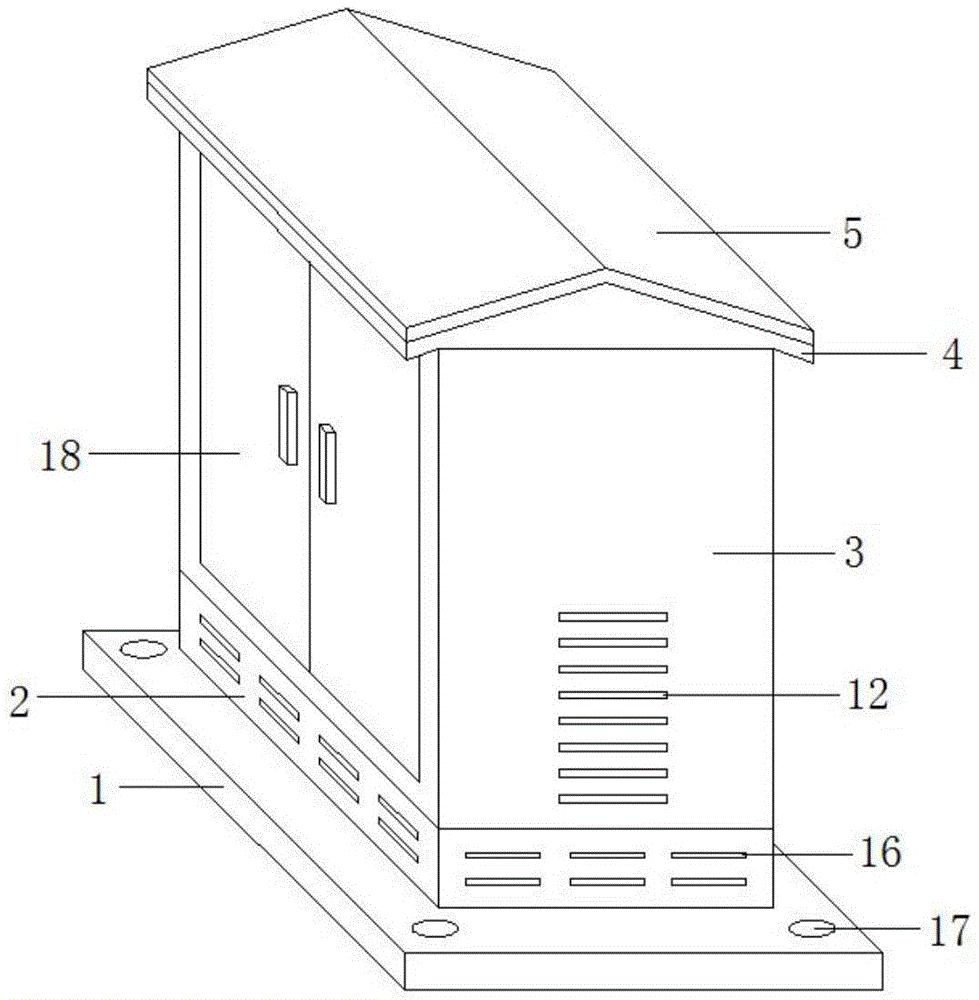
图1是本实用新型一种室外配电箱结构结构图。Figure 1 is a structural diagram of an outdoor distribution box of the present invention.
图2是本实用新型一种室外配电箱结构的配电箱体主视图。Fig. 2 is a front view of a distribution box body of an outdoor distribution box structure of the present invention.
图3是本实用新型一种室外配电箱结构的配电箱体结构图。3 is a structural diagram of a distribution box body of an outdoor distribution box structure of the present invention.
图4是本实用新型一种室外配电箱结构的散热箱结构图。4 is a structural diagram of a heat dissipation box of an outdoor distribution box structure of the present invention.
图中标号:1、底座;2、散热箱;3、配电箱体;4、顶板;5、太阳能电池板;6、电气安装板;7、蓄电池;8、内箱体;9、弹簧柱;10、外箱体;11、上散热槽;12、下散热槽;13、散热扇;14、吹风口;15、灰尘过滤网;16、进气口;17、固定孔;18、柜门。Labels in the figure: 1, base; 2, cooling box; 3, power distribution box; 4, top plate; 5, solar panel; 6, electrical installation plate; 7, battery; 8, inner box; 9, spring column ;10. Outer box; 11. Upper cooling slot; 12. Lower cooling slot; 13. Cooling fan; 14. Air outlet; 15. Dust filter; 16. Air inlet; 17. Fixing hole; 18. Cabinet door .
具体实施方式Detailed ways
以下结合附图对本实用新型的优选实施例进行说明,应当理解,此处所描述的优选实施例仅用于说明和解释本实用新型,并不用于限定本实用新型。The preferred embodiments of the present utility model will be described below with reference to the accompanying drawings. It should be understood that the preferred embodiments described herein are only used to illustrate and explain the present utility model, but not to limit the present utility model.
实施例一:Example 1:
如图1-图4所示,一种室外配电箱结构,包括底座1,所述底座1顶部固定设有散热箱2,所述散热箱2顶部固定设有配电箱体3,所述配电箱体3顶部固定设有顶板4,所述顶板4顶部固定设有太阳能电池板5,所述配电箱体3内腔后侧固定设有电气安装板6,设置电气安装板6方便对电气元件进行安装,所述电气安装板6顶部前侧表面固定设有蓄电池7,所述配电箱体3包括内箱体8,所述内箱体8外侧通过弹簧柱9连接有外箱体10,内箱体8与外箱体10之间通过弹簧柱9连接可以提高内箱体8的减震性能,可以防止配电箱体3内腔的电气元件受外界因素影响而剧烈震动,所述内箱体8顶部两侧等距对称设有上散热槽11,所述外箱体10底部两侧对称等距设有下散热槽12,通过设置上散热槽11与下散热槽12方便对配电箱体3内腔进行散热,所述配电箱体3内腔底部固定设有散热扇13,通过设置散热扇13可以对配电箱体3内腔的电气元件进行吹风散热,可以防止电气元件因温度过高而损坏,所述太阳能电池板5、蓄电池7、散热扇13之间通过导线依次连接。As shown in Figures 1-4, an outdoor power distribution box structure includes a
本实施例中,所述配电箱体3内腔底部挖设有吹风口14,所述吹风口14内腔固定设有灰尘过滤网15,设置吹风口14方便散热扇13对电气元件进行吹风散热,设置灰尘过滤网15可以防止灰尘进入配电箱体3内腔。In this embodiment, the bottom of the inner cavity of the
本实施例中,所述散热箱2上等距挖设有进气口16。In this embodiment,
本实施例中,所述底座1上位于其四角处对称挖设有固定孔17,方便对室外配电箱进行固定安装。In this embodiment,
本实施例中,所述配电箱体3前侧表面通过铰轴连接有柜门18。In this embodiment, the front surface of the
实施例二:Embodiment 2:
如图1和图3所示,所述上散热槽11的高度高于下散热槽12的高度,上散热槽11的高度高于下散热槽12的高度可以防止雨水进入配电箱体3内腔,防水性能好。As shown in FIG. 1 and FIG. 3 , the height of the
本实用新型工作原理:太阳能电池板5可以把太阳能转化为电能,蓄电池7可以对太阳能电池板5转化的电能进行储存,蓄电池7可以对散热扇13进行供电,散热扇13可以对配电箱体3内腔的电气元件进行吹风散热,可以防止电气元件因温度过高而损坏,设置上散热槽11与下散热槽12方便对配电箱体3内腔进行散热,上散热槽11的高度高于下散热槽12的高度可以防止雨水进入配电箱体3内腔,防水性能好,内箱体8与外箱体10之间通过弹簧柱9连接可以提高内箱体8的减震性能,可以防止配电箱体3内腔的电气元件受外界因素影响而剧烈震动。The working principle of the utility model: the
以上为本实用新型较佳的实施方式,本实用新型所属领域的技术人员还能够对上述实施方式进行变更和修改,因此,本实用新型并不局限于上述的具体实施方式,凡是本领域技术人员在本实用新型的基础上所作的任何显而易见的改进、替换或变型均属于本实用新型的保护范围。The above are the preferred embodiments of the present invention. Those skilled in the art can also make changes and modifications to the above-mentioned embodiments. Therefore, the present invention is not limited to the above-mentioned specific embodiments. Any obvious improvement, replacement or modification made on the basis of the present invention belongs to the protection scope of the present invention.
Claims (6)
Priority Applications (1)
| Application Number | Priority Date | Filing Date | Title |
|---|---|---|---|
| CN201921307266.5U CN209993975U (en) | 2019-08-13 | 2019-08-13 | An outdoor distribution box structure |
Applications Claiming Priority (1)
| Application Number | Priority Date | Filing Date | Title |
|---|---|---|---|
| CN201921307266.5U CN209993975U (en) | 2019-08-13 | 2019-08-13 | An outdoor distribution box structure |
Publications (1)
| Publication Number | Publication Date |
|---|---|
| CN209993975U true CN209993975U (en) | 2020-01-24 |
Family
ID=69297905
Family Applications (1)
| Application Number | Title | Priority Date | Filing Date |
|---|---|---|---|
| CN201921307266.5U Expired - Fee Related CN209993975U (en) | 2019-08-13 | 2019-08-13 | An outdoor distribution box structure |
Country Status (1)
| Country | Link |
|---|---|
| CN (1) | CN209993975U (en) |
Cited By (1)
| Publication number | Priority date | Publication date | Assignee | Title |
|---|---|---|---|---|
| CN115800031A (en) * | 2022-12-05 | 2023-03-14 | 福建和通电气有限公司 | A multifunctional portable distribution box and its use method |
-
2019
- 2019-08-13 CN CN201921307266.5U patent/CN209993975U/en not_active Expired - Fee Related
Cited By (1)
| Publication number | Priority date | Publication date | Assignee | Title |
|---|---|---|---|---|
| CN115800031A (en) * | 2022-12-05 | 2023-03-14 | 福建和通电气有限公司 | A multifunctional portable distribution box and its use method |
Similar Documents
| Publication | Publication Date | Title |
|---|---|---|
| CN104967020A (en) | Air blower electronic control cabinet | |
| CN211858725U (en) | Battery cabinet | |
| CN210534257U (en) | Device for positioning power grid fault | |
| CN210379796U (en) | Outdoor waterproof electric control cabinet with high-efficiency heat dissipation | |
| CN212784470U (en) | Box-type substation | |
| CN212343139U (en) | Power distribution cabinet with heat dissipation and moisture prevention effects | |
| CN203423839U (en) | Electronic ballast shell structure | |
| CN212726210U (en) | Explosion-proof type electrical control cabinet | |
| CN216648957U (en) | Energy-saving high-reliability distribution box | |
| CN219181040U (en) | Outdoor high-voltage switch cabinet | |
| CN222563346U (en) | Floor type distribution box | |
| CN212625071U (en) | Multifunctional transformer box | |
| CN214707235U (en) | Energy storage equipment based on wireless communication management | |
| JP2011165875A (en) | Electronic apparatus | |
| CN221633190U (en) | Transformer case that possesses lightning protection function | |
| CN221178087U (en) | Control display screen for controlling air supply motor | |
| CN219919357U (en) | Box structure of grounding detection device | |
| CN219936806U (en) | Isolation device | |
| CN209963589U (en) | Dustproof heat dissipation and ventilation's outdoor distribution box | |
| CN220122412U (en) | Block terminal with mounting bracket | |
| CN216981306U (en) | Trade cabinet battery and be equipped with electric installation | |
| CN220915247U (en) | Commercial power and solar energy complementary controller | |
| CN223871915U (en) | Capacitor box with cooling air duct structure | |
| CN212676732U (en) | Power transformation box | |
| CN221509621U (en) | Outdoor wireless bridge supporting reverse power supply |
Legal Events
| Date | Code | Title | Description |
|---|---|---|---|
| GR01 | Patent grant | ||
| GR01 | Patent grant | ||
| CF01 | Termination of patent right due to non-payment of annual fee |
Granted publication date: 20200124 |