CN219181040U - Outdoor high-voltage switch cabinet - Google Patents
Outdoor high-voltage switch cabinet Download PDFInfo
- Publication number
- CN219181040U CN219181040U CN202223414593.5U CN202223414593U CN219181040U CN 219181040 U CN219181040 U CN 219181040U CN 202223414593 U CN202223414593 U CN 202223414593U CN 219181040 U CN219181040 U CN 219181040U
- Authority
- CN
- China
- Prior art keywords
- cabinet
- outdoor high
- box
- utility
- switch cabinet
- Prior art date
- Legal status (The legal status is an assumption and is not a legal conclusion. Google has not performed a legal analysis and makes no representation as to the accuracy of the status listed.)
- Active
Links
- 238000009423 ventilation Methods 0.000 claims abstract description 14
- 238000009434 installation Methods 0.000 claims description 4
- 238000013461 design Methods 0.000 description 8
- 238000001816 cooling Methods 0.000 description 4
- 230000032683 aging Effects 0.000 description 3
- 230000002349 favourable effect Effects 0.000 description 3
- 230000017525 heat dissipation Effects 0.000 description 2
- 238000012544 monitoring process Methods 0.000 description 2
- 238000012545 processing Methods 0.000 description 2
- 230000009286 beneficial effect Effects 0.000 description 1
- 238000004891 communication Methods 0.000 description 1
- 230000007547 defect Effects 0.000 description 1
- 210000005069 ears Anatomy 0.000 description 1
- 230000000694 effects Effects 0.000 description 1
- 230000003993 interaction Effects 0.000 description 1
- 238000000034 method Methods 0.000 description 1
- 238000012986 modification Methods 0.000 description 1
- 230000004048 modification Effects 0.000 description 1
Images



Classifications
-
- Y—GENERAL TAGGING OF NEW TECHNOLOGICAL DEVELOPMENTS; GENERAL TAGGING OF CROSS-SECTIONAL TECHNOLOGIES SPANNING OVER SEVERAL SECTIONS OF THE IPC; TECHNICAL SUBJECTS COVERED BY FORMER USPC CROSS-REFERENCE ART COLLECTIONS [XRACs] AND DIGESTS
- Y02—TECHNOLOGIES OR APPLICATIONS FOR MITIGATION OR ADAPTATION AGAINST CLIMATE CHANGE
- Y02A—TECHNOLOGIES FOR ADAPTATION TO CLIMATE CHANGE
- Y02A30/00—Adapting or protecting infrastructure or their operation
- Y02A30/14—Extreme weather resilient electric power supply systems, e.g. strengthening power lines or underground power cables
Landscapes
- Patch Boards (AREA)
Abstract
The utility model belongs to the technical field of electric supporting facilities, and particularly relates to an outdoor high-voltage switch cabinet, which comprises an equipment box and an electric element, wherein the equipment box comprises a box cabinet and a box door, the electric element is arranged in the box cabinet, a fan is arranged at the top of the box cabinet, a temperature sensor is arranged on a mounting seat of the electric element, the temperature sensor is connected with a control unit of the fan, ventilation gaps are arranged at the bottoms of the side walls at the left side and the right side of the box cabinet.
Description
Technical Field
The utility model belongs to the technical field of electric supporting facilities, and particularly relates to an outdoor high-voltage switch cabinet.
Background
The switch cabinet is a device which is quite wide in application in matched power supply, and in many cases, the switch cabinet is arranged outdoors, however, when summer is carried out, especially when sunlight is strong, the temperature in the box is high, components in the switch cabinet are aged very fast, the service life of the switch cabinet is greatly shortened, the failure rate is high, and in view of the fact, the outdoor high-voltage switch cabinet is designed.
Disclosure of Invention
Aiming at the defects in the prior art, the utility model provides an outdoor high-voltage switch cabinet which is used for solving the problems that the prior switch cabinet is placed outdoors in many cases, but when in summer, especially when sunlight is strong, the temperature in the cabinet is high, the components in the switch cabinet are aged very fast, and the service life of the switch cabinet is greatly shortened.
In order to solve the technical problems, the utility model adopts the following technical scheme:
the utility model provides an outdoor high tension switchgear, includes equipment box and electrical components, the equipment box includes cabinet and chamber door, electrical components installs the inside at the cabinet, the fan is installed at the top of cabinet, install temperature-sensing ware on electrical components's the mount pad, temperature-sensing ware and the control unit of fan are connected, the lateral wall bottom of cabinet left and right sides is equipped with ventilation space.
Further, the electrical components are located higher than the ventilation gaps of the side walls of the cabinet.
Further, the cabinet and the door are movably connected through a hinge.
Further, the outside of the cabinet is provided with a mounting lug.
Further, a box lock is arranged on the box door.
Further, the bottom of the cabinet is provided with a vent hole.
Because the switch cabinet is installed in the outside of wall body through the installation ear, outdoor temperature is higher in hot summer, electrical components work can produce the heat in the switch cabinet moreover, if the heat dissipation is untimely, components and parts in the switch cabinet age very fast, can shorten its life by a wide margin, in view of this we design an outdoor high-voltage switch cabinet, this switch cabinet includes the trunk, install electrical components in the case, the fan is installed at the top of cabinet especially, install temperature-sensing ware on electrical components's the mount pad, temperature-sensing ware and fan's the control unit connection, after temperature-sensing ware detects the interior temperature of case is higher, just control fan's switch makes it work, cool down the processing to the cabinet, simultaneously through the bottom design ventilation hole at the cabinet, the lateral wall bottom design ventilation space in cabinet left and right sides can effectively promote cold and hot air circulation, be favorable to the cooling, prevent components and parts because of ambient temperature is too high and ageing fast, utilize temperature-sensing ware to realize intelligent monitoring, resources are saved.
Compared with the prior art, the utility model has the following beneficial effects:
1. utilize temperature-sensing ware and fan to realize intelligent monitoring cooling, save the resource, simultaneously through the bottom design ventilation hole in the cabinet, the lateral wall bottom design ventilation space in cabinet left and right sides can effectively promote cold and hot air circulation, is favorable to the cooling, prevents components and parts because of the high and quick ageing of ambient temperature, improves life.
Drawings
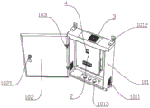
Fig. 1 is a schematic perspective view (view angle one) of an embodiment of an outdoor high-voltage switchgear of the present utility model;
fig. 2 is a schematic perspective view (view angle two) of an embodiment of an outdoor high-voltage switch cabinet according to the present utility model;
fig. 3 is a schematic perspective view of an embodiment of an outdoor high-voltage switchgear according to the present utility model (view angle three;
fig. 4 is a schematic perspective view (view angle four) of an embodiment of an outdoor high-voltage switchgear according to the present utility model
Reference numerals in the drawings of the specification include:
the device comprises a device box 1, an electrical element 2, a fan 3 and a temperature sensor 4;
Detailed Description
In order that those skilled in the art will better understand the present utility model, the following technical scheme of the present utility model will be further described with reference to the accompanying drawings and examples.
Wherein the drawings are for illustrative purposes only and are shown in schematic, non-physical, and not intended to be limiting of the present patent; for the purpose of better illustrating embodiments of the utility model, certain elements of the drawings may be omitted, enlarged or reduced and do not represent the size of the actual product; it will be appreciated by those skilled in the art that certain well-known structures in the drawings and descriptions thereof may be omitted.
The same or similar reference numbers in the drawings of embodiments of the utility model correspond to the same or similar components; in the description of the present utility model, it should be understood that, if the terms "upper", "lower", "left", "right", "inner", "outer", etc. indicate orientations or positional relationships based on the orientations or positional relationships shown in the drawings, only for convenience in describing the present utility model and simplifying the description, rather than indicating or implying that the apparatus or elements being referred to must have a specific orientation, be constructed and operated in a specific orientation, so that the terms describing the positional relationships in the drawings are merely for exemplary illustration and should not be construed as limiting the present patent, and that the specific meaning of the terms described above may be understood by those of ordinary skill in the art according to specific circumstances.
In the description of the present utility model, unless explicitly stated and limited otherwise, the term "coupled" or the like should be interpreted broadly, as it may be fixedly coupled, detachably coupled, or integrally formed, as indicating the relationship of components; can be mechanically or electrically connected; can be directly connected or indirectly connected through an intermediate medium, and can be communication between the two parts or interaction relationship between the two parts. The specific meaning of the above terms in the present utility model will be understood in specific cases by those of ordinary skill in the art.
Embodiment one:
as shown in fig. 1-4, the present utility model. Specifically, an outdoor high-voltage switch cabinet comprises an equipment box 1 and an electric element 2, wherein the equipment box 1 comprises a box 101 and a box door 102, the electric element 2 is installed inside the box 101, a fan 3 is installed at the top of the box 101, a temperature sensor 4 is installed on an installation seat of the electric element 2, the temperature sensor 4 is connected with a control unit of the fan 3, and ventilation gaps 1011 are formed in the bottoms of side walls of the left side and the right side of the box 101. The electrical component 2 is located higher than the ventilation gap 1011 in the side wall of the cabinet 101. The cabinet 101 and the door 102 are movably connected through a hinge 103. The outside of the cabinet 101 is provided with mounting ears 1012. The door 102 is provided with a door lock 1021. The bottom of the cabinet 101 is provided with a vent 1013.
Because the switch cabinet is installed in the outside of wall body through the installation ear 1012, outdoor temperature is higher in hot summer, and electric appliance element 2 work can produce heat in the switch cabinet, if the heat dissipation is untimely, components and parts in the switch cabinet age very fast, can shorten its life by a wide margin, in view of this we design an outdoor high-voltage switch cabinet, this switch cabinet includes trunk 1, install electric appliance element 2 in the case, especially fan 3 is installed at the top of cabinet 101, install temperature-sensing ware 4 on the mount pad of electric appliance element 2, temperature-sensing ware 4 is connected with the control unit of fan 3, after temperature-sensing ware 4 detects that the temperature is higher in the cabinet 101, just control fan 3's switch makes its work, cool down the processing to cabinet 101, simultaneously through design ventilation 1013 in the bottom of cabinet 101, the lateral wall bottom design space 1011 of cabinet 101 left and right sides can effectively promote cold and hot air circulation, be favorable to the cooling, prevent components and parts ageing fast because of ambient temperature is too high, utilize temperature-sensing ware 4 to realize intelligent control, resources are saved.
The foregoing is merely exemplary of the present utility model, and the specific structures and features well known in the art are not described in any way herein, so that those skilled in the art will be able to ascertain all prior art in the field, and will not be able to ascertain any prior art to which this utility model pertains, without the general knowledge of the skilled person in the field, before the application date or the priority date, to practice the present utility model, with the ability of these skilled persons to perfect and practice this utility model, with the help of the teachings of this application, with some typical known structures or methods not being the obstacle to the practice of this application by those skilled in the art. It should be noted that modifications and improvements can be made by those skilled in the art without departing from the structure of the present utility model, and these should also be considered as the scope of the present utility model, which does not affect the effect of the implementation of the present utility model and the utility of the patent.
Claims (6)
1. The utility model provides an outdoor high tension switchgear, includes equipment box (1) and electrical components (2), equipment box (1) include cabinet (101) and chamber door (102), electrical components (2) are installed in the inside of cabinet (101), fan (3) are installed at the top of cabinet (101), its characterized in that: the electric appliance is characterized in that a temperature sensor (4) is installed on an installation seat of the electric appliance element (2), the temperature sensor (4) is connected with a control unit of the fan (3), and ventilation gaps (1011) are formed in the bottoms of the side walls of the left side and the right side of the cabinet (101).
2. An outdoor high voltage switchgear as claimed in claim 1, wherein: the electric element (2) is positioned higher than the ventilation gap (1011) of the side wall of the cabinet (101).
3. An outdoor high voltage switchgear as claimed in claim 2, wherein: the cabinet (101) is movably connected with the box door (102) through a hinge (103).
4. An outdoor high-voltage switchgear according to claim 3, characterized in that: the outside of the cabinet (101) is provided with a mounting lug (1012).
5. An outdoor high-voltage switchgear according to claim 4, characterized in that: a box lock (1021) is arranged on the box door (102).
6. An outdoor high-voltage switchgear according to claim 5, characterized in that: the bottom of the cabinet (101) is provided with a vent hole (1013).
Priority Applications (1)
| Application Number | Priority Date | Filing Date | Title |
|---|---|---|---|
| CN202223414593.5U CN219181040U (en) | 2022-12-20 | 2022-12-20 | Outdoor high-voltage switch cabinet |
Applications Claiming Priority (1)
| Application Number | Priority Date | Filing Date | Title |
|---|---|---|---|
| CN202223414593.5U CN219181040U (en) | 2022-12-20 | 2022-12-20 | Outdoor high-voltage switch cabinet |
Publications (1)
| Publication Number | Publication Date |
|---|---|
| CN219181040U true CN219181040U (en) | 2023-06-13 |
Family
ID=86677012
Family Applications (1)
| Application Number | Title | Priority Date | Filing Date |
|---|---|---|---|
| CN202223414593.5U Active CN219181040U (en) | 2022-12-20 | 2022-12-20 | Outdoor high-voltage switch cabinet |
Country Status (1)
| Country | Link |
|---|---|
| CN (1) | CN219181040U (en) |
-
2022
- 2022-12-20 CN CN202223414593.5U patent/CN219181040U/en active Active
Similar Documents
| Publication | Publication Date | Title |
|---|---|---|
| CN107135631A (en) | A kind of water proof and dust proof regulator cubicle with heat sinking function | |
| CN214337298U (en) | A low-voltage distribution box with good heat dissipation performance | |
| CN214014880U (en) | Intelligent container machine room | |
| CN209516419U (en) | A distribution box for intelligent low-voltage power distribution | |
| CN217882390U (en) | Cabinet converges suitable for high-pressure energy storage system | |
| CN216489320U (en) | A cooling device for power distribution cabinet | |
| CN213906049U (en) | Energy-saving heat dissipation type high-low voltage complete set power distribution cabinet | |
| CN216720644U (en) | Electrical switch cabinet convenient to install | |
| CN218128040U (en) | Bottom plate subassembly and cooking device | |
| CN210723878U (en) | Outdoor power equipment box | |
| CN215010952U (en) | Elevator control cabinet with semiconductor refrigeration cooling system | |
| CN209993975U (en) | An outdoor distribution box structure | |
| CN213026981U (en) | Control cabinet for harbor electromechanical control equipment | |
| CN210608235U (en) | Ventilation device of capacitance compensation cabinet | |
| CN210669176U (en) | Block terminal for electrical engineering | |
| CN220233958U (en) | Heat preservation type intelligent control case | |
| CN218569647U (en) | Electric power protection automatic monitoring device | |
| CN211128803U (en) | Electric automation equipment control cabinet | |
| CN218828602U (en) | Heat insulation and cooling distribution box | |
| CN220511544U (en) | Control cabinet with heat dissipation function | |
| CN212726210U (en) | Explosion-proof type electrical control cabinet | |
| CN215374276U (en) | Intelligent electricity-saving control device for air conditioner of machine room | |
| CN215662997U (en) | Outdoor charging cabinet with heat insulation, cooling and self-cleaning functions | |
| CN213755523U (en) | High heat dissipation type integration power cabinet | |
| CN209217054U (en) | The radiator and battery case of battery case |
Legal Events
| Date | Code | Title | Description |
|---|---|---|---|
| GR01 | Patent grant | ||
| GR01 | Patent grant |