CN213460112U - Microneedle type lead connecting device - Google Patents
Microneedle type lead connecting device Download PDFInfo
- Publication number
- CN213460112U CN213460112U CN202022781656.5U CN202022781656U CN213460112U CN 213460112 U CN213460112 U CN 213460112U CN 202022781656 U CN202022781656 U CN 202022781656U CN 213460112 U CN213460112 U CN 213460112U
- Authority
- CN
- China
- Prior art keywords
- conductor
- conductive alloy
- needle
- wire
- micro
- Prior art date
- Legal status (The legal status is an assumption and is not a legal conclusion. Google has not performed a legal analysis and makes no representation as to the accuracy of the status listed.)
- Active
Links
- 239000000956 alloy Substances 0.000 claims abstract description 71
- 239000004020 conductor Substances 0.000 claims abstract description 63
- 229910045601 alloy Inorganic materials 0.000 claims abstract description 58
- 239000004519 grease Substances 0.000 claims description 9
- 229920006351 engineering plastic Polymers 0.000 claims description 6
- 239000012466 permeate Substances 0.000 claims description 4
- 230000001681 protective effect Effects 0.000 claims description 4
- 238000000034 method Methods 0.000 description 13
- 230000000694 effects Effects 0.000 description 4
- 238000004519 manufacturing process Methods 0.000 description 4
- 238000010586 diagram Methods 0.000 description 3
- 238000009434 installation Methods 0.000 description 3
- 238000007789 sealing Methods 0.000 description 3
- 230000002411 adverse Effects 0.000 description 2
- 239000006071 cream Substances 0.000 description 2
- 238000009413 insulation Methods 0.000 description 2
- 239000000463 material Substances 0.000 description 2
- 230000008569 process Effects 0.000 description 2
- APTZNLHMIGJTEW-UHFFFAOYSA-N pyraflufen-ethyl Chemical compound C1=C(Cl)C(OCC(=O)OCC)=CC(C=2C(=C(OC(F)F)N(C)N=2)Cl)=C1F APTZNLHMIGJTEW-UHFFFAOYSA-N 0.000 description 2
- 229910000881 Cu alloy Inorganic materials 0.000 description 1
- 230000009471 action Effects 0.000 description 1
- 238000007664 blowing Methods 0.000 description 1
- 230000007797 corrosion Effects 0.000 description 1
- 238000005260 corrosion Methods 0.000 description 1
- 238000004870 electrical engineering Methods 0.000 description 1
- 238000010292 electrical insulation Methods 0.000 description 1
- 238000005516 engineering process Methods 0.000 description 1
- 230000005307 ferromagnetism Effects 0.000 description 1
- 230000006872 improvement Effects 0.000 description 1
- 230000008595 infiltration Effects 0.000 description 1
- 238000001764 infiltration Methods 0.000 description 1
- 230000004048 modification Effects 0.000 description 1
- 238000012986 modification Methods 0.000 description 1
- 230000003647 oxidation Effects 0.000 description 1
- 238000007254 oxidation reaction Methods 0.000 description 1
- 230000000149 penetrating effect Effects 0.000 description 1
- 230000002093 peripheral effect Effects 0.000 description 1
- 239000002699 waste material Substances 0.000 description 1
- XLYOFNOQVPJJNP-UHFFFAOYSA-N water Substances O XLYOFNOQVPJJNP-UHFFFAOYSA-N 0.000 description 1
- 238000004078 waterproofing Methods 0.000 description 1
- 238000004804 winding Methods 0.000 description 1
Images


Landscapes
- Connections By Means Of Piercing Elements, Nuts, Or Screws (AREA)
Abstract
The utility model discloses a micro-needle type lead connecting device, which comprises an upper shell, a lower shell, a plurality of conductive alloy micro-needles and an electric conductor, wherein the upper shell and the lower shell are connected through a fastener; the lower shell is provided with a plurality of wire grooves, wires to be connected are placed in the wire grooves, and the lower surface of the upper shell can press the wires tightly; the conductor is arranged in the lower shell; the conductive alloy micro-needle is vertically arranged, the lower end of the conductive alloy micro-needle is fixedly connected with the conductor, the upper end of the conductive alloy micro-needle extends into the conductor groove, and the conductive alloy micro-needle penetrates through the insulating layer of the conductor and then is inserted into the bare conductor of the conductor. The utility model has the advantages that: the utility model discloses utilize high strength alloy material to make conductive alloy micropin, insert in the bare conductor after stabbing the wire insulating layer, carry out good contact with the bare conductor, guaranteed conductive alloy micropin and leading wire, auxiliary conductor's electrical area of contact, improved the electric conductivity between main, two auxiliary conductors.
Description
Technical Field
The utility model relates to a wire connection technology, concretely relates to micropin type wire connecting device.
Background
In electrical engineering, in particular in electrical line engineering, the connection of two insulated wires or bare conductors is very common. When the two wires are connected, the mechanical tensile strength, the electrical conduction capability and the electrical insulation strength between the two wires all meet the requirements under the condition of ensuring the electrical safety of operators. For convenience of description, the incorporated conductive wire is referred to as a main conductive wire, and the incorporated conductive wire is referred to as an auxiliary conductive wire. At present, the connection of a main lead and an auxiliary lead on site is carried out by the following three methods.
The first connection method comprises the following steps: the main conductor is a conductor which is in power-on operation, the auxiliary conductor is a conductor to be connected into a power-on circuit (a conductor to be connected with power), and in this case, the connection is usually performed by adopting a direct cross connection mutual winding method, a binding method or a branch T connection method of a main stranded conductor and an auxiliary stranded conductor. This connection method has the following problems: the high-altitude live-wire operation is extremely unsafe, the technical level requirement on operators is very high, the mechanical tensile strength cannot meet the requirement, and in the 'binding method' of the main wire and the auxiliary wire, the electrical conduction capability cannot meet the requirement, so that poor contact between the main wire and the auxiliary wire often occurs, and even oxidation and burning faults of the connecting part occur.
The second connection method is as follows: and the main conductor and the auxiliary conductor are connected by utilizing the parallel groove clamp. This method of connection is simple, but also has the following problems: the mechanical tensile strength, the electric conduction capability or the connection impedance value between the main lead and the auxiliary lead are difficult to meet the specified requirements, and the main lead and the auxiliary lead are bare leads. According to the relevant literature, the actual electrical contact area is only about 7% of the nominal contact surface.
The third connection method is as follows: when the main lead and the auxiliary lead are connected, only the auxiliary lead is required to be manufactured with a wire end and then electrified and ignited by utilizing a lengthened insulating operating rod; the drawbacks of this connection method are the same as in the second field case.
Disclosure of Invention
An object of the utility model is to provide a micropin type wire connecting device to prior art not enough.
The utility model adopts the technical proposal that: a micro-needle type lead connecting device comprises an upper shell, a lower shell, a plurality of conductive alloy micro-needles and a conductor, wherein the upper shell is connected with the lower shell through a fastener; the lower shell is provided with a plurality of wire grooves, wires to be connected are placed in the wire grooves, and the lower surface of the upper shell can press the wires tightly; the conductor is arranged in the lower shell; the conductive alloy micro-needle is vertically arranged, the lower end of the conductive alloy micro-needle is fixedly connected with the conductor, the upper end of the conductive alloy micro-needle extends into the conductor groove, and the conductive alloy micro-needle penetrates through the insulating layer of the conductor and then is inserted into the bare conductor of the conductor.
According to the scheme, insulating grease is filled in the wire groove of the lower shell; after the conductive alloy micro-needle punctures the insulating layer of the conducting wire, the insulating grease permeates into the gap between the conductive alloy micro-needle and the insulating layer.
According to the scheme, the fastening piece comprises a plurality of bolts and nuts, the bolts are evenly distributed along the circumferential direction of the upper shell and the lower shell at intervals, the nuts are matched with the bolts, and the upper shell and the lower shell are connected through the bolts.
According to the scheme, the conductive alloy micro-needle is made of a high-strength alloy material.
According to the scheme, the diameter of the conductive alloy micro-needle is 80-120 nanometers.
According to the scheme, the wire guide groove is an arc-shaped groove.
According to the scheme, the joint of the upper shell and the lower shell is additionally provided with the insulating sealing gasket, and the outer side surfaces of the upper shell and the lower shell are coated with the insulating protective sleeves.
According to the above scheme, go up the casing and be the cuboid structure with lower casing, the two is equallyd divide and is adopted insulating engineering plastics preparation respectively.
The utility model has the advantages that:
1. the utility model discloses utilize high strength alloy material to make conductive alloy micropin, insert in the naked conductor after stabbing the wire insulating layer, carry out good contact with the naked conductor, guaranteed conductive alloy micropin and main traverse line, auxiliary conductor's electric area of contact, improved the electric conductivity between two main, auxiliary wires; the conductive alloy micro-needle has high mechanical strength and hardness, is simple and labor-saving to penetrate through the insulating layer of the lead, can be stably inserted into the bare conductor of the lead and is reliable in connection.
2. The utility model discloses pack insulating cream fat in the metallic channel, after the insulating layer of wire was punctureed to the conductive alloy micropin, in the gap between insulating cream fat infiltration conductive alloy micropin and the insulating layer, when playing the insulating action, also played sealed effect, protected overall structure. The insulating pads or insulating protective sleeves which have insulating effect are respectively arranged at the joint of the upper shell and the lower shell and on the peripheral surface of the whole device, so that the external insulating strength of the main wire and the auxiliary wire after connection is improved.
3. The utility model discloses through bolted connection between the upper and lower casing in, bolt both sides symmetrical arrangement has improved the mechanical tensile strength between main, two wire of assistance, can prevent junction wire distortion simultaneously.
4. The utility model discloses the high strength alloy material quantity of well production conductive alloy micropin is few, and conductive alloy micropin's low in production cost. The casing adopts the preparation of insulating engineering plastics, and whole device is adaptable multiple adverse circumstances, does not fear the windy and blowing, the rain is beaten, the solarization, limiting temperature, thunderbolt, long service life.
Drawings
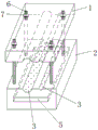
Fig. 1 is a schematic structural diagram of an embodiment of the present invention.
Fig. 2 is a front view of the present embodiment.
Fig. 3 is a schematic structural diagram of the lower housing in this embodiment.
Fig. 4 is a schematic diagram of the working state of the embodiment.
Wherein: 1. an upper housing; 2. a lower housing; 3. a wire guide groove; 4. a conductive alloy microneedle; 5. an electrical conductor; 6. a bolt; 7. a nut; 8. insulating grease; 9. an insulating gasket; 10. an insulating layer.
Detailed Description
For a better understanding of the present invention, reference is made to the following detailed description taken in conjunction with the accompanying drawings.
A micro-needle type lead connecting device as shown in fig. 1 comprises an upper shell 1, a lower shell 2, a plurality of conductive alloy micro-needles 4 and a conductor 5, wherein the upper shell 1 and the lower shell 2 are connected through a fastener; the lower shell 2 is provided with a plurality of wire grooves 3, wires to be connected are placed in the wire grooves 3, and the lower surface of the upper shell 1 can press the wires; the conductor is arranged in the lower shell 2; the conductive alloy micro-needle 4 is vertically arranged, the lower end of the conductive alloy micro-needle 4 is fixedly connected with the electric conductor 5, the upper end of the conductive alloy micro-needle 4 extends into the conductor groove 3, and the conductive alloy micro-needle penetrates into a bare conductor of the conductor after penetrating the insulating layer 10 of the conductor.
Preferably, the conductor groove 3 of the lower shell 2 is filled with insulating grease 8; after the conductive alloy micro-needle 4 pierces the insulating layer 10 of the lead, the insulating grease 8 permeates into the gap between the conductive alloy micro-needle 4 and the insulating layer 10, and plays a role in insulation and sealing.
Preferably, the fastener comprises a plurality of bolts 6 which are uniformly distributed along the circumferential direction of the upper shell and the lower shell at intervals, and nuts 7 which are matched with the bolts 6; the upper and lower shells are connected through the bolt 6, and along with the continuous approach of the upper and lower shells, the upper shell 1 continuously compresses the wire in the wire groove 3, and the conductive alloy micro-needle 4 punctures the insulating layer 10 of the wire, as shown in fig. 4.
Preferably, the conductive alloy micro-needle 4 is made of a high-strength alloy material, preferably a high-strength copper alloy material. The diameter of the conductive alloy micro-needle 4 is 80-120 nanometers.
Preferably, an insulating sealing gasket 9 is additionally arranged at the joint of the upper shell and the lower shell, and an insulating protective sleeve is coated on the outer side surface of the upper shell and the lower shell.
Preferably, the wire groove 3 is an arc-shaped groove, which can adapt to wires with different diameters. Specifically, the wire groove 3 on the lower casing 2 is an arc-shaped half-groove body structure, and is arranged opposite to the half-groove body arranged on the upper casing 1, and the two half-groove bodies can be spliced into a whole groove body matched with the wire.
Preferably, go up casing 1 and casing 2 down and be the cuboid structure, the two is equallyd divide and is adopted insulating engineering plastics preparation respectively.
Examples
The micro-needle type lead connecting device shown in fig. 1-3 comprises an upper shell 1, a lower shell 2, four bolts 6, a nut 7, a conductor 5 and a plurality of conductive alloy micro-needles 4 which are matched with each other. The upper shell 1 and the lower shell 2 are both of rectangular structures made of insulating engineering plastics and are connected through four bolts 6 uniformly distributed at four corners. The wire groove 3 on the lower shell 2 is a half-groove body structure, and is arranged opposite to the half-groove body arranged on the upper shell 1, and the two half-groove bodies can be spliced into a whole groove body matched with the wire. The conductor 5 housed in the lower case 2 has a plate-like structure, and the longitudinal direction thereof coincides with the axial direction of the wire guide groove 3.
When the electric wire and the cable need to be connected, the main lead and the auxiliary lead are respectively sleeved in the two lead grooves 3. The nut 7 is rotated, the upper shell 1 moves downwards, the lower surface (bottom surface of the half-groove body) of the upper shell 1 compresses the conducting wire, the conductive alloy micro-needle 4 gradually punctures the insulating layer 10 of the conducting wire and is inserted into the bare conductor inside the conducting wire, and the electric conduction of the two conducting wires is realized through the electric conductor 5; meanwhile, the insulating grease around the conductive alloy micro-needle 4 overflows and then permeates into the gap between the conductive alloy micro-needle 4 and the insulating layer 10, as shown in fig. 4.
The utility model discloses have following characteristic:
1) the conductive alloy micro-needle 4 has high mechanical strength.
The high-strength alloy material has extremely high strength and hardness, good plasticity, and excellent electrical conductivity, thermal conductivity, corrosion resistance, cold resistance, wear resistance and no ferromagnetism. By utilizing this characteristic, the conductive alloy micro-needle 4 made of high-strength alloy material has tensile strength>600MPa, hardness>200HV, sustainable clamping force and upsetting force>1.0×10⁶N, can easily penetrate the insulating layer 10 of the wire and be inserted into the bare conductor in good contact therewith and firmly connected therewith.
2) The conductive alloy micro-needle 4 has extremely low resistance.
The high-strength alloy material has extremely high strength and hardness and good plasticity, the electric conductivity is more than 80% IACS, the electric conductivity is higher than that of the wire cores of the main wire and the auxiliary wire by several orders of magnitude, and the current density is extremely high. By utilizing the characteristic, the conductive alloy micro-needle 4 can be directly in good contact with a bare conductor inside the lead, the electrical contact area of the conductive alloy micro-needle 4 with the main lead and the auxiliary lead is ensured, the contact resistance between the main lead conductor and the auxiliary lead conductor is extremely small and can be ignored, so that the electrical conduction capability between the main lead conductor and the auxiliary lead conductor is extremely strong and greatly exceeds the current density of the original lead conductor.
3) And the installation and operation process is safe.
The high strength alloy may be forged into acicular materials having a diameter of about 100 nanometers. The conductive alloy micro-needles 4 enter the interior of the bare conductor without causing damage to the insulating layer 10. Insulating grease 8 in the metallic channel 3 also plays insulating and sealed effect, goes up casing 1 and casing 2 down and adopts high mechanical strength, high dielectric strength's material preparation, and the insulating pad is established to the two junction, therefore the external electric insulation strength after main traverse line, the auxiliary wire are connected is high, need not dampproofing and waterproofing.
4) The installation operation is simple and labor-saving.
The conductive alloy micro-needle 4 has extremely high mechanical strength and hardness, can easily penetrate through the insulating layer 10 of the main conductor and the auxiliary conductor to be inserted into a bare conductor, and is time-saving and labor-saving.
5) And the alloy micro-needle has low price.
With the wide application of high-strength alloy materials, the production cost of the conductive alloy micro-needle 4 is lower and lower; and the consumption of high-strength alloy materials is less, and the mass production with low cost can be realized.
6) The waterproof, sun-proof and lightning-proof effects.
The direct connection mode of two wires of tradition or the connection mode through termination all have the shortcoming that fear water is afraid of shining, the utility model discloses totally enclosed, the casing adopts insulating engineering plastics preparation, and the adaptable multiple adverse circumstances of whole device is dreaded wind and is blown, rain is beaten, is shone, limit temperature, thunderbolt, long service life.
7) The connector is suitable for connecting various wires.
The utility model is suitable for a connection of single strand wire, stranded wire, circular telegram operation wire or cable, the new dress wire of having a power failure or the arbitrary combination of cable. The wire groove 3 is designed in an arc shape, is suitable for connecting wires with different sections, and does not need to strip the insulating layer 10.
8) And the mechanical tensile strength meets the requirement.
The four-bolt 6 has two sides installation mode, so that the main wire and the auxiliary wire are stressed uniformly, symmetrically and balanced, and the mechanical tensile strength is increased.
9) And can be repeatedly used.
The high-strength alloy material has extremely high strength, and the assembly and disassembly processes cannot cause the damage of all parts including the conductive alloy micro-needle 4, so that all parts can be repeatedly used, and the resource waste is avoided.
It should be noted that the above is only a preferred embodiment of the present invention, and the present invention is not limited thereto, and although the present invention has been described in detail with reference to the embodiments, it will be apparent to those skilled in the art that the technical solutions described in the foregoing embodiments can be modified or some technical features can be replaced with equivalents, but any modification, equivalent replacement, improvement, etc. made within the spirit and principle of the present invention should be included in the scope of the present invention.
Claims (8)
1. A micro-needle type lead connecting device is characterized by comprising an upper shell, a lower shell, a plurality of conductive alloy micro-needles and a conductor, wherein the upper shell is connected with the lower shell through a fastener; the lower shell is provided with a plurality of wire grooves, wires to be connected are placed in the wire grooves, and the lower surface of the upper shell can press the wires tightly; the conductor is arranged in the lower shell; the conductive alloy micro-needle is vertically arranged, the lower end of the conductive alloy micro-needle is fixedly connected with the conductor, the upper end of the conductive alloy micro-needle extends into the conductor groove, and the conductive alloy micro-needle penetrates through the insulating layer of the conductor and then is inserted into the bare conductor of the conductor.
2. A microneedle type wire connection device according to claim 1, wherein an insulating grease is filled in a wire groove of a lower case; after the conductive alloy micro-needle punctures the insulating layer of the conducting wire, the insulating grease permeates into the gap between the conductive alloy micro-needle and the insulating layer.
3. A microneedle type lead connecting device according to claim 1, wherein the fastening member comprises a plurality of bolts uniformly distributed at intervals in the circumferential direction of the upper and lower housings, and nuts engaged with the bolts, and the upper and lower housings are connected by the bolts.
4. A microneedle type wire connection device according to claim 1, wherein the conductive alloy microneedles are made of a high-strength alloy material.
5. The microneedle type wire connection apparatus according to claim 1, wherein the diameter of the conductive alloy microneedle is 80 to 120 nm.
6. A microneedle wire connection device according to claim 1, wherein the wire channel is an arcuate channel.
7. The microneedle type wire connecting device according to claim 1, wherein an insulating gasket is additionally provided at a joint between the upper and lower housings, and an insulating protective cover is coated on outer side surfaces of the upper and lower housings.
8. The microneedle type wire connection apparatus according to claim 1, wherein the upper case and the lower case are each of a rectangular parallelepiped structure, and are made of insulating engineering plastics, respectively.
Priority Applications (1)
| Application Number | Priority Date | Filing Date | Title |
|---|---|---|---|
| CN202022781656.5U CN213460112U (en) | 2020-11-26 | 2020-11-26 | Microneedle type lead connecting device |
Applications Claiming Priority (1)
| Application Number | Priority Date | Filing Date | Title |
|---|---|---|---|
| CN202022781656.5U CN213460112U (en) | 2020-11-26 | 2020-11-26 | Microneedle type lead connecting device |
Publications (1)
| Publication Number | Publication Date |
|---|---|
| CN213460112U true CN213460112U (en) | 2021-06-15 |
Family
ID=76303024
Family Applications (1)
| Application Number | Title | Priority Date | Filing Date |
|---|---|---|---|
| CN202022781656.5U Active CN213460112U (en) | 2020-11-26 | 2020-11-26 | Microneedle type lead connecting device |
Country Status (1)
| Country | Link |
|---|---|
| CN (1) | CN213460112U (en) |
-
2020
- 2020-11-26 CN CN202022781656.5U patent/CN213460112U/en active Active
Similar Documents
| Publication | Publication Date | Title |
|---|---|---|
| CN101546872B (en) | Device for connecting two superconducting cables | |
| CN205429234U (en) | High performance aluminum alloy cable junction terminal | |
| RU2014132554A (en) | CONNECTION METHOD, EQUIPOTENTIAL BRANCH CONNECTION ELEMENT AND REVERSE CURRENT NETWORK WITH EQUIPOTENTIAL CONNECTION IN A NON-CONDUCTING DESIGN | |
| CN210430151U (en) | Waterproof type binding post | |
| CN213460112U (en) | Microneedle type lead connecting device | |
| US2876190A (en) | Duct anode | |
| CN201655985U (en) | Thrusting earthing clamp | |
| CN101694907A (en) | Soft aluminum conductor crimping armor clamp and crimping method thereof | |
| CN110634600A (en) | Cable structure with automatic power-off cooling function | |
| JP5566772B2 (en) | Conductor connection method and conductor connection structure | |
| CN206878197U (en) | A kind of Quick connector plug for electrical wire | |
| CN201044267Y (en) | Wiring terminal | |
| CN112366461A (en) | Microneedle type lead connecting device | |
| CN209993731U (en) | Bimetallic end sleeve | |
| CN105098557A (en) | 2M cable head manufacturing process | |
| JP2019096532A (en) | Plug-in connector and connection structure | |
| CN203056527U (en) | Cable traction head | |
| CN102683916A (en) | Connection structure of BV wire | |
| CN203931563U (en) | Multi-core cable | |
| CN203192951U (en) | Novel parallel groove clamp | |
| CN208637989U (en) | Strain clamp for ice-melting ground wire | |
| CN205282698U (en) | Warm up binding post , circuit and electric heat | |
| CN218827859U (en) | Durable heating wire structure | |
| CN214754268U (en) | Connecting structure of soft connecting piece and applied this soft connecting piece | |
| CN216215844U (en) | 27.5kV railway cable connects and uses housing |
Legal Events
| Date | Code | Title | Description |
|---|---|---|---|
| GR01 | Patent grant | ||
| GR01 | Patent grant |