CN213459340U - Damp-proof internal circulation dry-type transformer convenient for heat dissipation - Google Patents
Damp-proof internal circulation dry-type transformer convenient for heat dissipation Download PDFInfo
- Publication number
- CN213459340U CN213459340U CN202023159909.1U CN202023159909U CN213459340U CN 213459340 U CN213459340 U CN 213459340U CN 202023159909 U CN202023159909 U CN 202023159909U CN 213459340 U CN213459340 U CN 213459340U
- Authority
- CN
- China
- Prior art keywords
- air
- box
- dry
- type transformer
- air return
- Prior art date
- Legal status (The legal status is an assumption and is not a legal conclusion. Google has not performed a legal analysis and makes no representation as to the accuracy of the status listed.)
- Active
Links
Images

Landscapes
- Photovoltaic Devices (AREA)
Abstract
The utility model relates to a dry-type transformer technical field especially relates to a dampproofing inner loop is convenient for radiating dry-type transformer. The solar energy power generation system is characterized in that an air outlet box is fixedly arranged at the bottom of the distribution box, the outlet end of the circulating fan is communicated with the air outlet box, a plurality of air outlets are distributed above the air outlet box, an air return box is arranged below the solar panel, the top of the air return cover is communicated with the air return box through a radiating pipe, one side of the air return box is connected with the inlet end of the circulating fan through a pipeline, the air outlets blow air to radiate heat on the dry-type transformer, then the air enters the radiating pipe outside the upper part, the air return box is cooled, and finally the air is blown to the dry-type transformer through the backflow of the circulating fan, so that a closed airflow circulating loop is formed inside and; the air flow is cooled by the double actions of the radiating pipe and the semiconductor refrigerating sheet, and the heat dissipation performance of the dry transformer is good.
Description
Technical Field
The utility model relates to a dry-type transformer technical field especially relates to a dampproofing inner loop is convenient for radiating dry-type transformer.
Background
In short, a dry transformer refers to a transformer in which the core and the winding are not immersed in insulating oil. A dry transformer is basically introduced: cooling by air convection is generally used for local illumination and electronic circuits; when compared with an oil-immersed transformer, the dry-type transformer has poor insulation effect; in south, the dry type transformer is rainy and humid in air, the phenomena of electric leakage, ignition and corrosion of transformer accessories are easily caused when the dry type transformer is used in a humid environment, and the service life of the transformer is shortened.
SUMMERY OF THE UTILITY MODEL
The utility model aims to solve the technical problem, it is not enough to provide the radiating dry-type transformer of dampproofing inner loop is convenient for to above-mentioned technique, include the fixed air-out case that is provided with in block terminal bottom, circulating fan's exit end and air-out case intercommunication, air-out case top subsection has a plurality of air outlets, solar panel below is provided with the return-air case, return-air cover top and return-air case pass through the cooling tube intercommunication, return-air case one side and circulating fan's entrance point pass through the pipe connection, and the air outlet is bloied and is used in the dry-type transformer and dispels the heat, then enters into the outside cooling tube in top and go on, cools off at the return-air case, blows to the dry-type transformer through circulating fan backward flow at last, forms closed air current circulation circuit inside and outside the block terminal, can; the air flow is cooled by the double actions of the radiating pipe and the semiconductor refrigerating sheet, and the heat dissipation performance of the dry transformer is good.
In order to solve the technical problem, the utility model discloses the technical scheme who adopts is: the transformer comprises a distribution box, a dry-type transformer and a built-in circulating heat dissipation device; the dry-type transformer is fixedly arranged inside the distribution box; the built-in circulating heat dissipation device is arranged on the distribution box; the built-in circulating heat dissipation device comprises a circulating fan, a pipeline and a solar panel; the top of the distribution box is provided with a bracket; the solar panel is fixedly arranged at the top of the bracket; and the circulating fan is fixedly arranged on one side of the bottom of the distribution box.
Further optimizing the technical scheme, an air outlet box is fixedly arranged at the bottom of the distribution box; the outlet end of the circulating fan is communicated with the air outlet box; a plurality of air outlets are distributed above the air outlet box; the air outlet faces the dry-type transformer.
Further optimizing the technical scheme, the top end inside the distribution box is fixedly provided with an air return cover; the top of the return air cover is provided with a plurality of radiating pipes; the cooling tube sets up between distribution box top and solar panel.
Further optimizing the technical scheme, an air return box is arranged below the solar panel; the top of the air return cover is communicated with the air return box through a radiating pipe; and one side of the air return box is connected with the inlet end of the circulating fan through a pipeline.
Further optimizing the technical scheme, the top of the air return box is provided with a semiconductor refrigeration sheet; the cold piece end of the semiconductor refrigeration piece is arranged inside the air return box, and the hot piece end of the semiconductor refrigeration piece is arranged outside the air return box; the semiconductor refrigeration piece generates power through the solar panel.
Compared with the prior art, the utility model has the advantages of it is following:
1. the air exit effect of blowing dispels the heat at dry-type transformer, then enters into the outside cooling tube in top and go on, cools off at the case that returns air, blows to dry-type transformer through circulating fan backward flow at last, forms closed air current circulation circuit inside and outside the block terminal, can not cause inside to become damp futilely because of external tide.
2. The air flow is cooled by the double actions of the radiating pipe and the semiconductor refrigerating sheet, and the heat dissipation performance of the dry transformer is good.
Drawings
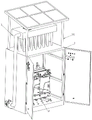
Fig. 1 is a perspective view of a dry type transformer with moisture-proof inner circulation for heat dissipation.
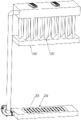
Fig. 2 is a schematic view of an external installation position of a built-in circulation heat dissipation device of a dry type transformer with moisture-proof internal circulation for facilitating heat dissipation.
Fig. 3 is a distribution structure diagram of a built-in circulation heat dissipation device of a dry type transformer with moisture-proof internal circulation for facilitating heat dissipation.
In the figure: 1. a distribution box; 101. a support; 2. a dry-type transformer; 3. a circulating heat dissipation device is arranged in the heat exchanger; 301. a circulating fan; 302. a pipeline; 303. a solar panel; 304. an air outlet box; 305. an air outlet; 306. a return air cover; 307. a radiating pipe; 308. an air return box; 309. semiconductor refrigeration piece.
Detailed Description
In order to make the objects, technical solutions and advantages of the present invention more apparent, the present invention will be described in detail with reference to the accompanying drawings. It should be understood that the description is intended to be illustrative only and is not intended to limit the scope of the present invention. Moreover, in the following description, descriptions of well-known structures and techniques are omitted so as to not unnecessarily obscure the concepts of the present invention.
The first embodiment is as follows: referring to fig. 1-3, a dry-type transformer with moisture-proof internal circulation for facilitating heat dissipation is characterized in that: the transformer comprises a distribution box 1, a dry-type transformer 2 and a built-in circulating heat dissipation device 3; the dry-type transformer 2 is fixedly arranged inside the distribution box 1; the built-in circulating heat dissipation device 3 is arranged on the distribution box 1; the built-in circulating heat dissipation device 3 comprises a circulating fan 301, a pipeline 302 and a solar panel 303; the top of the distribution box 1 is provided with a bracket 101; the solar panel 303 is fixedly arranged at the top of the bracket 101; circulating fan 301 is fixed and is set up in block terminal 1 bottom one side.
Preferably, an air outlet box 304 is fixedly arranged at the bottom of the distribution box 1; the outlet end of the circulating fan 301 is communicated with the air outlet box 304; a plurality of air outlets 305 are distributed above the air outlet box 304; the air outlet 305 faces the dry-type transformer 2.
Preferably, an air return cover 306 is fixedly arranged at the top end inside the distribution box 1; the top of the air return cover 306 is provided with a plurality of radiating pipes 307; the heat pipe 307 is disposed between the top of the distribution box 1 and the solar panel 303.
Preferably, an air return box 308 is arranged below the solar panel 303; the top of the air return cover 306 is communicated with the air return box 308 through a heat dissipation pipe 307; one side of the air return box 308 is connected with the inlet end of the circulating fan 301 through a pipeline 302.
Preferably, a semiconductor refrigerating sheet 309 is arranged at the top of the air return box 308; the cold plate end of the semiconductor refrigeration plate 309 is arranged inside the air return box 308, and the hot plate end is arranged outside the air return box 308; the semiconductor refrigerating plate 309 generates power through the solar panel 303.
The working principle is that, as shown in fig. 1-3, air is discharged from the outlet end under the action of the circulating fan 301, the bottom of the distribution box 1 is fixedly provided with an air outlet box 304, the outlet end of the circulating fan 301 is communicated with the air outlet box 304, a plurality of air outlets 305 are distributed above the air outlet box 304, the air outlets 305 face the dry-type transformer 2, the discharged air directly enters the air outlet box 304 and then is discharged from the air outlets 305, and the discharged air forms an upward flowing airflow below the dry-type transformer 2, so that the dry-type transformer 2 is cooled under the action of the flowing airflow.
The top end inside the distribution box 1 is fixedly provided with an air return cover 306, the top of the air return cover 306 is provided with a plurality of radiating pipes 307, the radiating pipes 307 are arranged between the top of the distribution box 1 and the solar panel 303, and air flow blows the air return cover 306 after radiating heat of the dry-type transformer 2 and then enters the radiating pipes 307 through the air return cover 306; the air return box 308 is arranged below the solar panel 303, the top of the air return cover 306 is communicated with the air return box 308 through a heat dissipation pipe 307, one side of the air return box 308 is connected with the inlet end of the circulating fan 301 through a pipeline 302, and finally enters the air return box 308 through the heat dissipation pipe 307 and flows back to the air inlet of the circulating fan 301 through the pipeline 302.
A circulating closed loop is formed among the power distribution cabinet, the air return box 308, the radiating pipe 307, the circulating fan 301 and the air inlet box, external damp air cannot enter the power distribution cabinet, and the interior of the power distribution cabinet cannot become damp due to external damp.
Since the heat pipe 307 is disposed outside the upper portion of the distribution box 1, when air flows through the heat pipe 307, the heat on the surface of the heat pipe 307 can be taken away by the air flows, so as to achieve the heat dissipation effect of the heat pipe 307 under the action of natural wind.
The air return box 308 top is provided with semiconductor refrigeration piece 309, the cold piece end setting of semiconductor refrigeration piece 309 is inside air return box 308, and the hot piece end sets up in air return box 308 outside, semiconductor refrigeration piece 309 passes through solar panel 303 electricity generation power supply, and solar panel 303 can generate electricity, drives semiconductor refrigeration piece 309 work through the controller, and the cold piece end is refrigerated to carry out the precooling cooling to air returning box 308 inside, and the hot piece end then is located external natural heat dissipation.
The air flow is cooled by double functions of the radiating pipe 307 and the semiconductor refrigerating sheet 309, and the dry-change radiating performance is good.
The utility model discloses a control mode comes automatic control through the controller, and the control circuit of controller can realize through the simple programming of technical staff in this field, belongs to the common general knowledge in this field, and the utility model discloses mainly be used for protecting mechanical device, so the utility model discloses no longer explain control mode and circuit connection in detail.
It is to be understood that the above-described embodiments of the present invention are merely illustrative of or explaining the principles of the invention and are not to be construed as limiting the invention. Therefore, any modification, equivalent replacement, improvement and the like made without departing from the spirit and scope of the present invention should be included in the protection scope of the present invention. Further, it is intended that the appended claims cover all such variations and modifications as fall within the scope and boundaries of the appended claims or the equivalents of such scope and boundaries.
Claims (5)
1. The utility model provides a dampproofing inner loop is convenient for radiating dry-type transformer which characterized in that: comprises a distribution box (1), a dry-type transformer (2) and a built-in circulating heat dissipation device (3); the dry-type transformer (2) is fixedly arranged inside the distribution box (1); the built-in circulating heat dissipation device (3) is arranged on the distribution box (1); the built-in circulating heat dissipation device (3) comprises a circulating fan (301), a pipeline (302) and a solar panel (303); the top of the distribution box (1) is provided with a bracket (101); the solar panel (303) is fixedly arranged at the top of the bracket (101); circulating fan (301) are fixed to be set up in block terminal (1) bottom one side.
2. A dry-type transformer with moisture-proof internal circulation for facilitating heat dissipation as recited in claim 1, wherein: an air outlet box (304) is fixedly arranged at the bottom of the distribution box (1); the outlet end of the circulating fan (301) is communicated with the air outlet box (304); a plurality of air outlets (305) are distributed above the air outlet box (304); the air outlet (305) faces the dry-type transformer (2).
3. A dry-type transformer with moisture-proof internal circulation for facilitating heat dissipation as recited in claim 1, wherein: an air return cover (306) is fixedly arranged at the top end inside the distribution box (1); the top of the air return cover (306) is provided with a plurality of radiating pipes (307); the radiating pipe (307) is arranged between the top of the distribution box (1) and the solar panel (303).
4. A dry-type transformer with moisture-proof internal circulation for facilitating heat dissipation as recited in claim 3, wherein: an air return box (308) is arranged below the solar panel (303); the top of the air return cover (306) is communicated with the air return box (308) through a radiating pipe (307); one side of the air return box (308) is connected with the inlet end of the circulating fan (301) through a pipeline (302).
5. A dry-type transformer with moisture-proof internal circulation for facilitating heat dissipation as recited in claim 4, wherein: a semiconductor refrigerating sheet (309) is arranged at the top of the air return box (308); the cold piece end of the semiconductor refrigeration piece (309) is arranged inside the air return box (308), and the hot piece end is arranged outside the air return box (308); the semiconductor refrigerating plate (309) generates electricity and supplies power through the solar panel (303).
Priority Applications (1)
| Application Number | Priority Date | Filing Date | Title |
|---|---|---|---|
| CN202023159909.1U CN213459340U (en) | 2020-12-25 | 2020-12-25 | Damp-proof internal circulation dry-type transformer convenient for heat dissipation |
Applications Claiming Priority (1)
| Application Number | Priority Date | Filing Date | Title |
|---|---|---|---|
| CN202023159909.1U CN213459340U (en) | 2020-12-25 | 2020-12-25 | Damp-proof internal circulation dry-type transformer convenient for heat dissipation |
Publications (1)
| Publication Number | Publication Date |
|---|---|
| CN213459340U true CN213459340U (en) | 2021-06-15 |
Family
ID=76305190
Family Applications (1)
| Application Number | Title | Priority Date | Filing Date |
|---|---|---|---|
| CN202023159909.1U Active CN213459340U (en) | 2020-12-25 | 2020-12-25 | Damp-proof internal circulation dry-type transformer convenient for heat dissipation |
Country Status (1)
| Country | Link |
|---|---|
| CN (1) | CN213459340U (en) |
Cited By (1)
| Publication number | Priority date | Publication date | Assignee | Title |
|---|---|---|---|---|
| CN114778975A (en) * | 2022-04-14 | 2022-07-22 | 合肥诚越电子科技有限公司 | Auxiliary detection device for rectifier manufacturing and detection method thereof |
-
2020
- 2020-12-25 CN CN202023159909.1U patent/CN213459340U/en active Active
Cited By (1)
| Publication number | Priority date | Publication date | Assignee | Title |
|---|---|---|---|---|
| CN114778975A (en) * | 2022-04-14 | 2022-07-22 | 合肥诚越电子科技有限公司 | Auxiliary detection device for rectifier manufacturing and detection method thereof |
Similar Documents
| Publication | Publication Date | Title |
|---|---|---|
| CN108495538B (en) | High-power outdoor heat dissipation rack | |
| CN105392339B (en) | Electrical cabinet | |
| CN211879964U (en) | Cold-storage type water-cooling box-type substation | |
| CN213459340U (en) | Damp-proof internal circulation dry-type transformer convenient for heat dissipation | |
| CN205566117U (en) | Dc -to -ac converter device with heat radiation structure | |
| CN211981469U (en) | Electric power is with outdoor cable branch case of safe type | |
| CN114915003A (en) | Heat dissipation device for multi-source power supply of team level | |
| CN210778150U (en) | Transformer heat abstractor | |
| CN207559391U (en) | A kind of box-type substation | |
| CN213484221U (en) | High-efficient heat dissipation electric power cabinet of inner loop for electric power cabinet | |
| CN108471685A (en) | A kind of novel electric control box | |
| CN108561979A (en) | Electrical apparatus box, off-premises station, photovoltaic air conditioning system and electrical equipment | |
| CN213584897U (en) | Indoor transformer substation with cooling equipment | |
| CN210404503U (en) | High-efficient heat abstractor of transformer substation | |
| KR200493401Y1 (en) | Battery cooling system | |
| CN208796765U (en) | A kind of high/low pressure conversion device of good heat dissipation effect | |
| CN207966668U (en) | A kind of heat dissipating device of transformer | |
| JP3079337U (en) | Outdoor iron box for storing electrical equipment | |
| CN208462179U (en) | A kind of novel electric control box | |
| CN208720368U (en) | Electrical apparatus box, off-premises station, photovoltaic air conditioning system and electrical equipment | |
| CN221353647U (en) | External protection device for power distribution equipment user | |
| CN210984464U (en) | Transformer with good heat dissipation performance | |
| CN206806774U (en) | A kind of high voltage power distributing cabinet of remote monitoring function | |
| CN110061428A (en) | A kind of dust-proof radiating switchgear | |
| CN217882380U (en) | Automatic intelligent power distribution cabinet who adjusts temperature |
Legal Events
| Date | Code | Title | Description |
|---|---|---|---|
| GR01 | Patent grant | ||
| GR01 | Patent grant |