CN213435986U - Concrete grit material separator - Google Patents
Concrete grit material separator Download PDFInfo
- Publication number
- CN213435986U CN213435986U CN202022315767.7U CN202022315767U CN213435986U CN 213435986 U CN213435986 U CN 213435986U CN 202022315767 U CN202022315767 U CN 202022315767U CN 213435986 U CN213435986 U CN 213435986U
- Authority
- CN
- China
- Prior art keywords
- roller
- cylinder
- tank
- water
- frame
- Prior art date
- Legal status (The legal status is an assumption and is not a legal conclusion. Google has not performed a legal analysis and makes no representation as to the accuracy of the status listed.)
- Active
Links
Images


Landscapes
- Separation Of Solids By Using Liquids Or Pneumatic Power (AREA)
Abstract
The utility model discloses a concrete grit material separator, riding wheel movable mounting is in the frame, is provided with annular spacing groove respectively at the front portion and the rear portion of cylinder, and the cylinder is slope form activity through annular spacing groove and erects on the riding wheel, and first motor fixed mounting is in the frame to be connected with the cylinder transmission, has seted up the feed inlet in the front portion of cylinder, has seted up the discharge gate at the rear portion of cylinder, is provided with spiral gusset and shoveling plate on the inside wall of cylinder, has seted up the hole of permeating water on the lateral wall of cylinder, basin fixed mounting is in the frame, and the basin is located the cylinder lower part, is provided with the feeder hopper in the frame, is provided with guide cylinder in feeder hopper department, and this guide cylinder is corresponding with the feed inlet of cylinder, is provided with the discharge pipe in the bottom of basin, and the intercommunication has the valve on the discharge pipe: has good sand and stone separation effect, good recycling effect and very convenient classification and use in the later period.
Description
Technical Field
The utility model relates to a concrete recovery unit's technical field, the more specifically technical field who relates to concrete recovery separator that says so.
Background
The concrete mixing plant is a combined device for intensively mixing concrete, is also called as a concrete precast yard, has high productivity due to high mechanization and automation degree, can ensure the quality of the concrete and save cement, and is commonly used for large-scale and medium-scale water conservancy, electric power, bridge and other projects with large concrete engineering quantity, long construction period and centralized construction sites. In the process of producing and processing concrete in a concrete mixing plant, raw materials such as sand and stone materials, fly ash, cement, a water reducing agent, water and the like need to be fully mixed and stirred by a concrete mixer to prepare the concrete. After the concrete is produced and processed in the concrete mixing plant, the concrete is transported to a construction site through a concrete tank truck, in order to save resources and production cost and protect the environment, the unused concrete slurry in the concrete tank truck is generally transported back to the concrete mixing plant again, and sand and stones in the concrete slurry are separated through a concrete sand-stone separator for recycling. However, the separation effect of the common concrete sand-stone separator is poor at present, and a large amount of sand is still mixed in the separated stones, so that the concrete sand-stone separator is inconvenient for later classified use.
SUMMERY OF THE UTILITY MODEL
The utility model aims at solving the above-mentioned not enough and provide one kind and can play fine separation effect to the stone and the sand in the concrete slurry, can play fine recycle effect, the concrete grit material separator of the categorised use in the later stage of very being convenient for.
The utility model discloses a solve above-mentioned technical problem and the technical solution who adopts as follows:
the concrete grit material separating device comprises a rack, a water tank, a riding wheel, a roller, a first motor, a bracket, a spring, a sieve hopper, a vibrating motor, a separating tank, a rotating shaft, a second motor, a sedimentation tank, a water pump and a spray pipe, wherein the riding wheel is movably arranged on the rack, the front part and the rear part of the roller are respectively provided with an annular limiting groove, the roller is movably arranged on the riding wheel in an inclined shape through the annular limiting groove, the first motor is fixedly arranged on the rack and is in transmission connection with the roller, the front part of the roller is provided with a feed inlet, the rear part of the roller is provided with a discharge outlet, the inner side wall of the roller is provided with a spiral rib plate and a shoveling plate, the side wall of the roller is provided with a permeable hole, the water tank is fixedly arranged on the rack, the water tank is positioned at the lower part of the roller, the rack is provided with a feed hopper, the bottom of the water tank is provided with a discharge pipe, the discharge pipe is communicated with a valve, the sieve hopper is fixedly arranged on a bracket in an inclined shape through a spring, a discharge port of the roller is positioned above the front part of the sieve hopper, a sieve mesh is arranged on the bottom wall of the sieve hopper, a blanking bin is arranged at the sieve mesh at the bottom of the sieve hopper, a blanking port is arranged at the bottom of the blanking bin, a vibrating motor is fixedly arranged on the blanking bin, a separation tank is positioned below the blanking port and the discharge pipe and is in a V shape, a discharge chute extending upwards in an inclined direction is arranged on the separation tank, a discharge port is arranged on the discharge chute, a rotating shaft is movably arranged in the separation tank and the discharge chute, a second motor is fixedly arranged on the discharge chute and is in transmission connection with the rotating shaft, a spiral conveying plate is arranged on the rotating shaft, an overflow groove is arranged on the upper edge of the separation tank and is positioned above the sedimentation tank, the spray pipe is provided with a spray head, the water outlet of the water pump is communicated with the spray pipe, and the water inlet of the water pump is communicated with the interior of the sedimentation tank.
The device also comprises a shaft sleeve and sealing filler, wherein the rotating shaft is movably arranged in the separation tank and the discharge chute through a bearing, the shaft sleeve is fixedly arranged at the bottom of the separation tank, the lower end part of the rotating shaft penetrates through the shaft sleeve, and the sealing filler is clamped in the shaft sleeve and sleeved outside the rotating shaft.
The outer side wall of the front part of the roller is provided with a first belt pulley, the output shaft of the first motor is provided with a second belt pulley, and the second belt pulley is in belt transmission connection with the first belt pulley.
The water outlet of the water pump is communicated with the spray pipe through a pipeline, and the water inlet of the water pump is communicated with the interior of the sedimentation tank through a water inlet pipe.
The utility model adopts the beneficial effect that above-mentioned technical solution can reach is: clear water is filled in a water tank, the lower part of a roller is soaked in the water tank, concrete slurry is conveyed through a spiral rib plate in the roller, the concrete slurry is turned through a shoveling plate, stones and sands in the concrete slurry are cleaned in the turning and conveying process, the stones and the sands in the concrete slurry are pre-separated, the stones and the sands pre-separated through the roller are discharged into a sieve hopper, the sieve hopper is driven by a vibrating motor to be vibrated and sieved, meanwhile, upper clear water in a sedimentation tank is pumped to a spray pipe through a water pump, the upper clear water is sprayed through a spray head to separate the stones and the sands, the separated stones are discharged from the rear part of the sieve hopper, the sands and the water pass through sieve holes to fall into a blanking bin and fall into a separation tank from a blanking port, the sands in the separation tank are conveyed through a spiral conveying plate, and are discharged from a discharge port of a discharge chute, the separation of stones and sands in the concrete slurry is completed, and the separated stones are basically not mixed with sands, so that the good sand-stone separation effect is achieved, the recycling effect is good, and the classification in the later period is very convenient.
Drawings
Fig. 1 is a schematic structural view of the present invention;
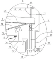
FIG. 2 is an enlarged view of a portion of FIG. 1 at A;
FIG. 3 is an enlarged view of a portion of FIG. 1 at B;
FIG. 4 is an enlarged view of a portion of FIG. 1 at C;
fig. 5 is an enlarged partial view of fig. 1 at D.
Detailed Description
As shown in fig. 1, the concrete, sand and stone separating device includes a frame 1, a water tank 2, a riding wheel 3, a roller 4, a first motor 5, a bracket 6, a spring 7, a screening bucket 8, a vibration motor 31, a separation tank 9, a rotating shaft 10, a second motor 11, a sedimentation tank 12, a water pump 13, a spray pipe 14, a shaft sleeve 39 and a sealing filler 40, as shown in fig. 2, the riding wheel 3 is movably mounted on the frame 1, annular limiting grooves 15 are respectively arranged at the front and rear of the roller 4, the roller 4 is movably mounted on the riding wheel 3 in an inclined shape through the annular limiting grooves 15, the first motor 5 is fixedly mounted on the frame 1 and is in transmission connection with the roller 4, and the concrete transmission connection relationship between the first motor 5 and the roller 4 is as follows: a first belt pulley 16 is arranged on the outer side wall of the front part of the roller 4, a second belt pulley 17 is arranged on the output shaft of the first motor 5, and the second belt pulley 17 is in transmission connection with a belt 18 of the first belt pulley 16. A feed inlet 19 is arranged at the front part of the roller 4, a discharge outlet 20 is arranged at the rear part of the roller 4, a spiral rib plate 21 and a shoveling plate 22 are arranged on the inner side wall of the roller 4, a water permeable hole 23 is arranged on the side wall of the roller 4, the water tank 2 is fixedly arranged on the frame 1, the water tank 2 is positioned at the lower part of the roller 4, a feed hopper 24 is arranged on the frame 1, a guide cylinder 25 is arranged at the feed hopper 24, the guide cylinder 25 corresponds to the feed inlet 19 of the roller 4, as shown in fig. 3, a discharge pipe 26 is arranged at the bottom of the water tank 2, a valve 27 is communicated with the discharge pipe 26, and the valve. Sieve fill 8 is slope form fixed bolster through spring 7 and puts on support 6, and the discharge gate 20 of cylinder 4 is located the anterior top of sieve fill 8, has seted up sieve mesh 28 on the diapire of sieve fill 8, is provided with blanking storehouse 29 in sieve mesh 28 department of sieve fill 8 bottom, has seted up blanking mouth 30 in blanking storehouse 29's bottom, and vibrating motor 31 fixed mounting is on blanking storehouse 29. The separation tank 9 is located blanking mouth 30 and discharge pipe 26 below, and this separation tank 9 is the V-arrangement, is provided with the blown down tank 32 that extends in the slant on the separation tank 9, has seted up bin outlet 33 on blown down tank 32, and is shown by figure 4, and pivot 10 passes through bearing 34 movable mounting in separation tank 9 and blown down tank 32, axle sleeve 39 fixed mounting is in the bottom of separation tank 9, and the lower tip of pivot 10 passes in the axle sleeve 39, sealing filler 40 card is put in axle sleeve 39 to the cover is put in the pivot 10 outside. The second motor 11 is fixedly installed on the discharge chute 32 and is in transmission connection with the rotating shaft 10, the rotating shaft 10 is provided with a spiral conveying plate 35, as shown in fig. 5, the upper edge of the separation tank 9 is provided with an overflow chute 36, the overflow chute 36 is positioned above the sedimentation tank 12, the spray pipe 14 is positioned above the sieve hopper 8, the spray pipe 14 is provided with a spray head 37, the water outlet of the water pump 13 is communicated with the spray pipe 14 through a pipeline 41, and the water inlet of the water pump 13 is communicated with the interior of the sedimentation tank 12 through a water inlet pipe 38.
When the concrete grit material separating device works, clear water is filled in the water tank 2, so that the lower part of the roller 4 is immersed in the water tank 2, the concrete slurry is discharged into the roller 4 through the feed hopper 24, the guide cylinder 25 and the feed inlet 19, the roller 4 is driven to rotate by the first motor 5, the concrete slurry is conveyed by the spiral rib plate 21 in the roller 4, the concrete slurry is turned and copied by the copying plate 22, and in the process of turning, copying and conveying, the concrete slurry is cleaned from stones and sands, and is pre-separated, the cement suspension and a part of sands in the concrete slurry fall into the water tank 2 from the water permeable holes 23, the valve 27 is opened at intervals, the slurry and the sands in the water tank 2 are discharged into the separation tank 9 through the discharge pipe 26, and fresh clean water is supplied into the water tank 2. The stones and sands pre-separated by the roller 4 are discharged into the sieve hopper 8 from the discharge hole 20 of the roller, the sieve hopper 8 is driven by the vibration motor 31 to carry out vibration sieve, meanwhile, the upper clear water in the sedimentation tank 12 is pumped to the spray pipe 14 by the water pump 13 and is sprayed by the spray nozzle 37, the stones and the sand are separated, the separated stones are discharged from the rear part of the sieve hopper 8, the sand and the water pass through the sieve holes 28 and fall into the blanking bin 29 and the separation tank 9 from the blanking port 30, the rotating shaft 10 is driven by the second motor 11 to rotate, the sand in the separation tank 9 is conveyed by the spiral conveying plate 35, the sand is discharged from the discharge opening 33 of the discharge chute 32, the separation of the stones and the sand in the concrete slurry is completed, the cement suspension in the separation tank 9 overflows from the overflow chute 36 into the sedimentation tank 12, and the water is precipitated in the sedimentation tank 12, and the upper clear water in the sedimentation tank 12 is recycled through the water pump 13.
Claims (4)
1. Concrete grit material separator, its characterized in that: the device comprises a frame, a water tank, a riding wheel, a roller, a first motor, a bracket, a spring, a sieve hopper, a vibrating motor, a separating tank, a rotating shaft, a second motor, a sedimentation tank, a water pump and a spray pipe, wherein the riding wheel is movably arranged on the frame, the front part and the rear part of the roller are respectively provided with an annular limiting groove, the roller is movably arranged on the riding wheel in an inclined shape through the annular limiting groove, the first motor is fixedly arranged on the frame and is in transmission connection with the roller, the front part of the roller is provided with a feed inlet, the rear part of the roller is provided with a discharge outlet, the inner side wall of the roller is provided with a spiral rib plate and a shoveling plate, the side wall of the roller is provided with a water permeable hole, the water tank is fixedly arranged on the frame, the water tank is positioned at the lower part of the roller, the frame is provided with a feed hopper, the feed, the discharge pipe is communicated with a valve, the sieve hopper is fixedly arranged on a bracket in an inclined manner through a spring, a discharge port of the roller is positioned above the front part of the sieve hopper, sieve meshes are arranged on the bottom wall of the sieve hopper, a blanking bin is arranged at the sieve mesh at the bottom of the sieve hopper, a blanking port is arranged at the bottom of the blanking bin, a vibration motor is fixedly arranged on the blanking bin, the separation tank is positioned below the blanking port and the discharge pipe and is in a V shape, a discharge chute extending in an inclined direction is arranged on the separation tank, a discharge port is arranged on the discharge chute, a rotating shaft is movably arranged in the separation tank and the discharge chute, a second motor is fixedly arranged on the discharge chute and is in transmission connection with the rotating shaft, a spiral conveying plate is arranged on the rotating shaft, an overflow groove is arranged on the upper edge of the separation tank and is positioned above the sedimentation tank, the spray pipe is positioned above the sieve hopper, and a spray head is, the water outlet of the water pump is communicated with the spray pipe, and the water inlet of the water pump is communicated with the interior of the sedimentation tank.
2. The concrete grit material separating apparatus as claimed in claim 1, wherein: the device also comprises a shaft sleeve and sealing filler, wherein the rotating shaft is movably arranged in the separation tank and the discharge chute through a bearing, the shaft sleeve is fixedly arranged at the bottom of the separation tank, the lower end part of the rotating shaft penetrates through the shaft sleeve, and the sealing filler is clamped in the shaft sleeve and sleeved outside the rotating shaft.
3. The concrete grit material separating apparatus as claimed in claim 2, wherein: the outer side wall of the front part of the roller is provided with a first belt pulley, the output shaft of the first motor is provided with a second belt pulley, and the second belt pulley is in belt transmission connection with the first belt pulley.
4. A concrete grit material separating apparatus as claimed in claim 1, 2 or 3, wherein: the water outlet of the water pump is communicated with the spray pipe through a pipeline, and the water inlet of the water pump is communicated with the interior of the sedimentation tank through a water inlet pipe.
Priority Applications (1)
| Application Number | Priority Date | Filing Date | Title |
|---|---|---|---|
| CN202022315767.7U CN213435986U (en) | 2020-10-18 | 2020-10-18 | Concrete grit material separator |
Applications Claiming Priority (1)
| Application Number | Priority Date | Filing Date | Title |
|---|---|---|---|
| CN202022315767.7U CN213435986U (en) | 2020-10-18 | 2020-10-18 | Concrete grit material separator |
Publications (1)
| Publication Number | Publication Date |
|---|---|
| CN213435986U true CN213435986U (en) | 2021-06-15 |
Family
ID=76292190
Family Applications (1)
| Application Number | Title | Priority Date | Filing Date |
|---|---|---|---|
| CN202022315767.7U Active CN213435986U (en) | 2020-10-18 | 2020-10-18 | Concrete grit material separator |
Country Status (1)
| Country | Link |
|---|---|
| CN (1) | CN213435986U (en) |
Cited By (1)
| Publication number | Priority date | Publication date | Assignee | Title |
|---|---|---|---|---|
| CN113634546A (en) * | 2021-08-19 | 2021-11-12 | 江西科技学院 | Waste water circulating system for collecting concrete waste |
-
2020
- 2020-10-18 CN CN202022315767.7U patent/CN213435986U/en active Active
Cited By (1)
| Publication number | Priority date | Publication date | Assignee | Title |
|---|---|---|---|---|
| CN113634546A (en) * | 2021-08-19 | 2021-11-12 | 江西科技学院 | Waste water circulating system for collecting concrete waste |
Similar Documents
| Publication | Publication Date | Title |
|---|---|---|
| CN104788033A (en) | Building waste recycling method | |
| CN204294385U (en) | A kind ofly to reclaim and the device of tailings glass for fine sand | |
| CN112058463B (en) | Concrete clout recovery processing system | |
| CN209035050U (en) | Tank car cleaning material recycling and reusing device | |
| CN209034870U (en) | Tank car cleaning material grading plant | |
| CN110665934A (en) | Construction waste's recovery processing system | |
| CN213435986U (en) | Concrete grit material separator | |
| CN112934348A (en) | Dry-process dust-free environment-friendly sand making equipment for machine-made sand | |
| CN210009715U (en) | Sand and stone separating device | |
| CN204509124U (en) | A kind of building waste recycling reutilization system | |
| CN208869512U (en) | Concrete recycle cyclic utilization system | |
| CN204523748U (en) | A kind of building waste treatment system | |
| CN216459123U (en) | Ore crushing and screening device for quartz stone processing | |
| CN115445741A (en) | Method for preparing sand by utilizing rock waste high-yield preparation machine | |
| KR100263819B1 (en) | The method of producing pulverized gravels and grinded sand for building materials and a apparatus for proceeding the same | |
| CN210385127U (en) | Sand and stone separating and recovering device | |
| KR20020024355A (en) | Manufacturing Device of Remaking gravel | |
| CN209533795U (en) | A kind of slurry-water recovery system | |
| CN206981173U (en) | A kind of dustless screening plant of construction waste | |
| CN217450936U (en) | Concrete residual waste recycling device for concrete mixing ship | |
| CN216573549U (en) | High-precision coal mining production coal washing device with screening mechanism | |
| CN221714546U (en) | Building type production system for preparing mortar from coal gangue | |
| CN210304082U (en) | High-speed vortex spiral sorting unit | |
| CN212791798U (en) | Grading separator of sand for concrete processing and manufacturing | |
| CN218637923U (en) | Glass cullet washs sieving mechanism |
Legal Events
| Date | Code | Title | Description |
|---|---|---|---|
| GR01 | Patent grant | ||
| GR01 | Patent grant |