CN213279539U - New forms of energy power generation facility convenient to installation - Google Patents
New forms of energy power generation facility convenient to installation Download PDFInfo
- Publication number
- CN213279539U CN213279539U CN202021489708.5U CN202021489708U CN213279539U CN 213279539 U CN213279539 U CN 213279539U CN 202021489708 U CN202021489708 U CN 202021489708U CN 213279539 U CN213279539 U CN 213279539U
- Authority
- CN
- China
- Prior art keywords
- fixedly connected
- power generation
- energy power
- rail
- base
- Prior art date
- Legal status (The legal status is an assumption and is not a legal conclusion. Google has not performed a legal analysis and makes no representation as to the accuracy of the status listed.)
- Active
Links
- 238000010248 power generation Methods 0.000 title claims abstract description 14
- 238000009434 installation Methods 0.000 title claims description 18
- 238000006243 chemical reaction Methods 0.000 abstract description 4
- 230000008901 benefit Effects 0.000 description 3
- 230000004048 modification Effects 0.000 description 2
- 238000012986 modification Methods 0.000 description 2
- 230000009286 beneficial effect Effects 0.000 description 1
- 230000005540 biological transmission Effects 0.000 description 1
- 230000000694 effects Effects 0.000 description 1
- 230000005611 electricity Effects 0.000 description 1
- 230000009466 transformation Effects 0.000 description 1
Images

Classifications
-
- Y—GENERAL TAGGING OF NEW TECHNOLOGICAL DEVELOPMENTS; GENERAL TAGGING OF CROSS-SECTIONAL TECHNOLOGIES SPANNING OVER SEVERAL SECTIONS OF THE IPC; TECHNICAL SUBJECTS COVERED BY FORMER USPC CROSS-REFERENCE ART COLLECTIONS [XRACs] AND DIGESTS
- Y02—TECHNOLOGIES OR APPLICATIONS FOR MITIGATION OR ADAPTATION AGAINST CLIMATE CHANGE
- Y02E—REDUCTION OF GREENHOUSE GAS [GHG] EMISSIONS, RELATED TO ENERGY GENERATION, TRANSMISSION OR DISTRIBUTION
- Y02E10/00—Energy generation through renewable energy sources
- Y02E10/40—Solar thermal energy, e.g. solar towers
- Y02E10/47—Mountings or tracking
-
- Y—GENERAL TAGGING OF NEW TECHNOLOGICAL DEVELOPMENTS; GENERAL TAGGING OF CROSS-SECTIONAL TECHNOLOGIES SPANNING OVER SEVERAL SECTIONS OF THE IPC; TECHNICAL SUBJECTS COVERED BY FORMER USPC CROSS-REFERENCE ART COLLECTIONS [XRACs] AND DIGESTS
- Y02—TECHNOLOGIES OR APPLICATIONS FOR MITIGATION OR ADAPTATION AGAINST CLIMATE CHANGE
- Y02E—REDUCTION OF GREENHOUSE GAS [GHG] EMISSIONS, RELATED TO ENERGY GENERATION, TRANSMISSION OR DISTRIBUTION
- Y02E10/00—Energy generation through renewable energy sources
- Y02E10/50—Photovoltaic [PV] energy
Landscapes
- Photovoltaic Devices (AREA)
Abstract
The utility model relates to the technical field of electric power, in particular to a new energy power generation device convenient to install, which comprises a base, wherein the middle part of the upper end of the base is rotatably connected with a rotating shaft, the upper end of the periphery of the rotating shaft is sleeved and fixed with a pinion, the right side of the upper end of the base is fixedly connected with a stepping motor, the upper end of the stepping motor is rotatably connected with a master gear, the upper end of the rotating shaft is fixedly connected with a bearing plate, the left side of the upper end of the bearing plate is fixedly connected with a hydraulic telescopic shaft, the upper end of the bearing plate is fixedly connected with a support frame; the rotation through the rotation axis is convenient for adjust solar cell panel's locating position, and through the flexible of hydraulic telescoping shaft, is convenient for adjust solar panel's inclination, consequently can carry out angle adjustment to different climatic change or geographical position, makes it carry out the conversion of utilizing of maximum to solar energy.
Description
Technical Field
The utility model relates to an electric power tech field especially relates to a new forms of energy power generation facility convenient to installation.
Background
Electric power is an energy source using electric energy as power. In the 70 s of the 19 th century, the invention and application of electric power opened up the second industrialized climax. The system becomes one of three scientific and technological revolution which occur in the world since 18 th century of human history, the life of people is changed by science, and a large-scale power system which appears in the 20 th century is one of the most important achievements in the science history of human engineering and is a power production and consumption system which consists of links of power generation, power transmission, power transformation, power distribution, power utilization and the like.
Present new forms of energy power generation facility when generating electricity through solar cell panel, need install solar cell panel fixed, but be difficult to carry out quick location to the mounted position in the middle of the installation, and need use more bolt, lead to the installation step too loaded down with trivial details, so that the installation is convenient inadequately, solar cell panel's locating position and inclination are difficult for adjusting moreover, are difficult to carry out angle modulation to different climatic change or geographical position, make it limited to solar energy conversion rate.
SUMMERY OF THE UTILITY MODEL
The utility model provides a new forms of energy power generation facility convenient to installation to be difficult to quick location when solving the installation that above-mentioned background art provided, it is convenient inadequately to install, and locating position and inclination are difficult for the problem of adjusting.
In order to solve the prior art problem, the utility model discloses a new forms of energy power generation facility convenient to installation, including the base:
the middle part of the upper end of the base is rotatably connected with a rotating shaft, the upper end of the periphery of the rotating shaft is fixedly sleeved with a pinion, the right side of the upper end of the base is fixedly connected with a stepping motor, the upper end of the stepping motor is rotatably connected with a master gear, the upper end of the rotating shaft is fixedly connected with a bearing plate, the left side of the upper end of the bearing plate is fixedly connected with a hydraulic telescopic shaft, the upper end of the bearing plate is fixedly arranged on the right side of the hydraulic telescopic shaft and is fixedly connected with a support frame, the upper end of the support frame is rotatably connected with a support plate, the left side of the lower end of the support plate is fixedly connected with a slide rail, the lower end of the slide rail is slidably connected with a slide block, four corners of the upper end of the support plate are fixedly connected with fixed rods, and the equal fixedly connected with locating lever in push pedal upper end four corners, the equal fixedly connected with T type rail in the mounting panel upper end left and right sides, just equal sliding connection has T template, two in the T type rail fixedly connected with solar cell panel between the upper end of the T template.
Furthermore, the upper end of the hydraulic telescopic shaft is rotatably connected with the sliding block, and the sliding block slides left and right along the sliding rail.
Furthermore, the front end of the T-shaped rail is an open end, and the T-shaped plate slides back and forth along the T-shaped rail through the open end.
Furthermore, the upper end of the positioning rod penetrates through the mounting plate and the T-shaped rail, positioning holes are formed in the front portion and the rear portion of the lower end of the T-shaped plate, the positioning rod is connected with the positioning holes in an inserting mode, and the positioning rod is connected with the mounting plate and the T-shaped rail in a sliding mode.
Furthermore, the solar cell panel is the slope form, just base lower extreme fixedly connected with a plurality of rubber support.
Compared with the prior art, the utility model discloses the beneficial effect who realizes:
rotation through the rotation axis is convenient for adjust solar cell panel's locating position, and through the flexible of hydraulic telescoping shaft, be convenient for adjust solar panel's inclination, consequently can carry out angle adjustment to different climatic change or geographical position, make it carry out the conversion of utilizing of at utmost to solar energy, and through the sliding connection of T template and T type rail, do benefit to quick installation solar cell panel, the installation convenience has been guaranteed, and insert the locating hole through the locating lever, the stability after the installation has been guaranteed.
Drawings
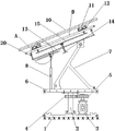
Fig. 1 is a schematic view of the overall structure of the present invention;
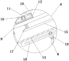
FIG. 2 is a schematic view of a partially enlarged structure A of the present invention;
fig. 3 is a schematic view of the push plate of the present invention.
In FIGS. 1-3: the device comprises a base 1, a rotating shaft 2, a stepping motor 3, a pinion 4, a main gear 5, a bearing plate 6, a support frame 7, a hydraulic telescopic shaft 8, a mounting plate 9, a solar cell panel 10, a T-shaped plate 11, a T-shaped rail 12, a support plate 13, a threaded push rod 14, a push plate 15, a positioning hole 16, a positioning rod 17, a sliding rail 18, a sliding block 19 and a fixing rod 20.
Detailed Description
The following description is provided for illustrative purposes, and other advantages and features of the present invention will become apparent to those skilled in the art from the following detailed description.
Please refer to fig. 1 to 3:
the utility model provides a new forms of energy power generation facility convenient to installation, includes base 1:
a rotating shaft 2 is rotatably connected to the middle of the upper end of the base 1, a pinion 4 is fixedly sleeved on the upper end of the periphery of the rotating shaft 2, a stepping motor 3 is fixedly connected to the right side of the upper end of the base 1, a main gear 5 is rotatably connected to the upper end of the stepping motor 3, a bearing plate 6 is fixedly connected to the upper end of the rotating shaft 2, a hydraulic telescopic shaft 8 is fixedly connected to the left side of the upper end of the bearing plate 6, a support frame 7 is fixedly connected to the upper end of the bearing plate 6 and positioned on the right side of the hydraulic telescopic shaft 8, a support plate 13 is rotatably connected to the upper end of the support frame 7, a slide rail 18 is fixedly connected to the left side of the lower end of the support plate 13, a slide block 19 is slidably connected to the lower end of the slide rail 18, fixed rods 20 are fixedly connected to four corners of the upper end of the, and the slide block 19 slides left and right along the slide rail 18;
specifically, because solar cell panel 10 is located mounting panel 9, drive master gear 5 through step motor 3 and rotate, master gear 5 then drives pinion 4 and rotation axis 2 and rotates, thereby make bearing plate 6 rotate, support frame 7 then drives extension board 13, dead lever 20 and mounting panel 9 rotate, consequently, be convenient for adjust solar cell panel 10's locating position, and make hydraulic telescoping shaft 8 stretch out and draw back from top to bottom, slider 19 then carries out the horizontal slip in slide rail 18, be convenient for prop up extension board 13, then be convenient for adjust solar cell panel 10's inclination this moment, do benefit to and carry out angle adjustment to different climatic change or geographical position, make it carry out the maximum conversion that utilizes to solar energy.
A threaded push rod 14 is connected with the middle of the support plate 13 through threads, a push plate 15 is rotatably connected between the support plate 13 and the mounting plate 9 at the tail end of the threaded push rod 14, positioning rods 17 are fixedly connected with four corners of the upper end of the push plate 15, T-shaped rails 12 are fixedly connected with the left side and the right side of the upper end of the mounting plate 9, T-shaped plates 11 are slidably connected in the T-shaped rails 12, a solar cell panel 10 is fixedly connected between the upper ends of the two T-shaped plates 11, the upper ends of the positioning rods 17 penetrate through the mounting plate 9 and the T-shaped rails 12, positioning holes 16 are formed in the front and the rear parts of the lower ends of the T-shaped plates 11, the positioning rods 17 are inserted into the positioning holes 16, and the positioning rods 17 are slidably;
further, when the solar cell panel 10 needs to be installed on the installation plate 9, the T-shaped plate 11 is installed in the T-shaped rail 12 in a sliding mode, the solar cell panel 10 is installed and positioned on the installation plate 9 quickly, installation convenience is guaranteed, the threaded push rod 14 is screwed, the threaded push rod 14 drives the push plate 15 and the positioning rod 17 to move upwards, the positioning rod 17 is inserted into the positioning hole 16, the T-shaped plate 11 cannot slide in the T-shaped rail 12 continuously at the moment, and stability after installation is guaranteed.
The front end of the T-shaped rail 12 is an open end, and the T-shaped plate 11 slides back and forth along the T-shaped rail 12 through the open end;
furthermore, the front end of the T-shaped rail 12 is an open end, so that the T-shaped plate 11 can quickly slide into the T-shaped rail 12 through the open end.
The solar cell panel 10 is inclined, and the lower end of the base 1 is fixedly connected with a plurality of rubber support columns;
furthermore, the rubber support column has certain elasticity, so that the vibration of the device is reduced, and the stability of the device is improved.
The above embodiments are merely illustrative of the principles and effects of the present invention, and are not to be construed as limiting the invention. Modifications and variations can be made to the above-described embodiments by those skilled in the art without departing from the spirit and scope of the present invention. Accordingly, it is intended that all equivalent modifications or changes which may be made by those skilled in the art without departing from the spirit and technical spirit of the present invention be covered by the claims of the present invention.
Claims (5)
1. The utility model provides a new forms of energy power generation facility convenient to installation, includes base (1), its characterized in that:
the middle part of the upper end of the base (1) is rotatably connected with a rotating shaft (2), the upper end of the periphery of the rotating shaft (2) is fixedly sleeved with a pinion (4), the right side of the upper end of the base (1) is fixedly connected with a stepping motor (3), the upper end of the stepping motor (3) is rotatably connected with a main gear (5), the upper end of the rotating shaft (2) is fixedly connected with a bearing plate (6), the left side of the upper end of the bearing plate (6) is fixedly connected with a hydraulic telescopic shaft (8), the upper end of the bearing plate (6) is fixedly positioned on the right side of the hydraulic telescopic shaft (8) and is fixedly connected with a support frame (7), the upper end of the support frame (7) is rotatably connected with a support plate (13), the left side of the lower end of the support plate (13) is fixedly connected with a sliding rail (18), the lower end of the sliding, four fixedly connected with mounting panel (9) between dead lever (20) upper end, extension board (13) middle part threaded connection has screw thread push rod (14), screw thread push rod (14) end just is located extension board (13) with rotate between mounting panel (9) and be connected with push pedal (15), just equal fixedly connected with locating lever (17) in push pedal (15) upper end four corners, the equal fixedly connected with T type rail (12) of mounting panel (9) upper end left and right sides, just inside equal sliding connection of T type rail (12) has T template (11), two fixedly connected with solar cell panel (10) between T template (11) upper end.
2. The new energy power generation device convenient to install according to claim 1, wherein: the upper end of the hydraulic telescopic shaft (8) is rotatably connected with the sliding block (19), and the sliding block (19) slides left and right along the sliding rail (18).
3. The new energy power generation device convenient to install according to claim 1, wherein: the front end of the T-shaped rail (12) is an open end, and the T-shaped plate (11) slides forwards and backwards along the T-shaped rail (12) through the open end.
4. The new energy power generation device convenient to install according to claim 1, wherein: locating lever (17) upper end runs through mounting panel (9) and T type rail (12), just locating hole (16) have all been opened to T type board (11) lower extreme front and back portion, locating lever (17) with locating hole (16) are pegged graft, just locating lever (17) with mounting panel (9) and T type rail (12) sliding connection.
5. The new energy power generation device convenient to install according to claim 1, wherein: the solar cell panel (10) is inclined, and the lower end of the base (1) is fixedly connected with a plurality of rubber supporting columns.
Priority Applications (1)
| Application Number | Priority Date | Filing Date | Title |
|---|---|---|---|
| CN202021489708.5U CN213279539U (en) | 2020-07-25 | 2020-07-25 | New forms of energy power generation facility convenient to installation |
Applications Claiming Priority (1)
| Application Number | Priority Date | Filing Date | Title |
|---|---|---|---|
| CN202021489708.5U CN213279539U (en) | 2020-07-25 | 2020-07-25 | New forms of energy power generation facility convenient to installation |
Publications (1)
| Publication Number | Publication Date |
|---|---|
| CN213279539U true CN213279539U (en) | 2021-05-25 |
Family
ID=75968794
Family Applications (1)
| Application Number | Title | Priority Date | Filing Date |
|---|---|---|---|
| CN202021489708.5U Active CN213279539U (en) | 2020-07-25 | 2020-07-25 | New forms of energy power generation facility convenient to installation |
Country Status (1)
| Country | Link |
|---|---|
| CN (1) | CN213279539U (en) |
Cited By (1)
| Publication number | Priority date | Publication date | Assignee | Title |
|---|---|---|---|---|
| CN114094927A (en) * | 2021-11-18 | 2022-02-25 | 芜湖铎成新能源有限公司 | Solar power generation device capable of automatically adjusting angle according to sun position |
-
2020
- 2020-07-25 CN CN202021489708.5U patent/CN213279539U/en active Active
Cited By (1)
| Publication number | Priority date | Publication date | Assignee | Title |
|---|---|---|---|---|
| CN114094927A (en) * | 2021-11-18 | 2022-02-25 | 芜湖铎成新能源有限公司 | Solar power generation device capable of automatically adjusting angle according to sun position |
Similar Documents
| Publication | Publication Date | Title |
|---|---|---|
| CN213279539U (en) | New forms of energy power generation facility convenient to installation | |
| CN113258643B (en) | Environment-friendly solar lithium battery charging device | |
| CN213392513U (en) | Support frame for wind turbine generator system | |
| CN215981756U (en) | Wisdom energy system show platform | |
| CN213870126U (en) | Portable wind power generation support | |
| CN112289192A (en) | Label based on solar power generation and installation method thereof | |
| CN221728210U (en) | Flexible solar photovoltaic panel convenient to installation | |
| CN221263692U (en) | Solar photovoltaic panel capable of being adjusted at multiple angles | |
| CN220783761U (en) | Photovoltaic panel installation auxiliary device for photovoltaic power generation | |
| CN214900721U (en) | Photovoltaic power generation device convenient to installation | |
| CN220511039U (en) | New energy photovoltaic power generation device with high practicability | |
| CN213450697U (en) | Fan blade maintenance platform for wind power generation | |
| CN219041701U (en) | Photovoltaic flexible support end supporting structure | |
| CN221428823U (en) | Adjustable light Fu Zhi | |
| CN220234545U (en) | Outdoor photovoltaic energy storage equipment mounting frame convenient for angle adjustment | |
| CN221227450U (en) | Clamp for photovoltaic panel installation | |
| CN218335848U (en) | Daylighting angle adjustable solar cell panel | |
| CN218720066U (en) | Display screen convenient to install for shelter | |
| CN219322306U (en) | Photovoltaic power generation assembly convenient to adjust | |
| CN215268144U (en) | Solar panel support structure | |
| CN221531382U (en) | Photovoltaic power generation mounting frame | |
| CN219732559U (en) | Quick detach formula photovoltaic ceiling fixed fastener | |
| CN221575244U (en) | Multi-angle photovoltaic power generation device | |
| CN219197534U (en) | Stable support for wind power generation | |
| CN216929943U (en) | Novel truss fixing system for flexible photovoltaic support |
Legal Events
| Date | Code | Title | Description |
|---|---|---|---|
| GR01 | Patent grant | ||
| GR01 | Patent grant | ||
| TR01 | Transfer of patent right | ||
| TR01 | Transfer of patent right |
Effective date of registration: 20220112 Address after: 264000 floor 26, West Tower, Chuangye building, No. 69, Keji Avenue, high tech Zone, Yantai City, Shandong Province Patentee after: State power investment group electric energy nuclear power equipment Co.,Ltd. Address before: 338000 building 4, Jiangshan Yujing, xinxinbei Avenue, Yushui District, Xinyu City, Jiangxi Province Patentee before: Wang Bingxue |