CN213268820U - Pull rod type I-steel cantilever beam - Google Patents
Pull rod type I-steel cantilever beam Download PDFInfo
- Publication number
- CN213268820U CN213268820U CN202022127065.6U CN202022127065U CN213268820U CN 213268820 U CN213268820 U CN 213268820U CN 202022127065 U CN202022127065 U CN 202022127065U CN 213268820 U CN213268820 U CN 213268820U
- Authority
- CN
- China
- Prior art keywords
- steel
- sleeve
- draw bar
- embedded
- steel beam
- Prior art date
- Legal status (The legal status is an assumption and is not a legal conclusion. Google has not performed a legal analysis and makes no representation as to the accuracy of the status listed.)
- Active
Links
Images





Landscapes
- Forms Removed On Construction Sites Or Auxiliary Members Thereof (AREA)
Abstract
The main body of the pull rod type I-steel cantilever beam comprises an I-steel beam, an embedded sleeve, a diagonal draw bar and a movable positioning device, wherein a seat plate at one end of the I-steel beam is fixedly connected with a building structure beam through the embedded sleeve, one end of the diagonal draw bar is connected with an upper pull lug plate of the I-steel beam, the other end of the diagonal draw bar is fixedly connected with the building structure beam through a U-shaped pull ring, the diagonal draw bar comprises a positive screw rod and a negative screw rod through a closed basket in the middle, two ends of the closed basket are respectively provided with a corresponding forward and reverse thread inner buckle, the movable positioning device is movably arranged at the end part of the I-steel beam, and the movable positioning device comprises a positioning groove plate. The utility model discloses need not to pass the wall body, can not destroy the concrete beam plate structure, the I-steel consumptive material is few, and the installation is demolishd and is need not the tower crane cooperation, lightweight operation, convenient and fast, shaped steel beam regularization preparation, and the specification model is few, and the turnover is high, and the back is demolishd to the cantilever beam of the load frame of encorbelmenting moreover, and the wall is clean and tidy, and no any destruction can practice thrift repair time.
Description
Technical Field
The utility model relates to a construction facility technical field, concretely relates to pull rod formula I-steel cantilever beam.
Background
In recent years, cities are rapidly developed, high-rise buildings are more and more common in city construction, building structures are increasingly complex, and external wall scaffolds are important measures for ensuring the safety and smooth proceeding of building main body structures and external wall decoration construction, so that the external wall scaffolds are widely used in the field of building construction. According to the 3.2.1 regulation of the safety technical unified Standard for scaffold for building construction GB51210-2016, under the condition of the safety level II, the height of the floor type steel pipe scaffold does not exceed 40 meters, and the height of each section of the cantilever type steel pipe scaffold does not exceed 20 meters. Therefore, during the construction of high-rise buildings, overhanging scaffolds are erected in sections at about every 18 meters of height. In order to ensure the safety and stability of the cantilever scaffold, a supporting structure, namely a profile steel cantilever beam, must be erected at the bottom of the cantilever scaffold.
The traditional overhanging type steel beam must pass through the outer wall of a building, stretch into the room and lay on the floor of a main structure, and then a plurality of U-shaped embedded parts are anchored on a floor plate and a floor beam, so that the layout of the steel beam stretching into the room is complex, and the indoor building garbage cleaning and the walking of constructors are hindered. The steel section penetrates through the wall body, so that concrete beams and plate members are easy to damage, and water seepage and leakage of the floor are easy to cause. Before the section steel beam is dismantled, the U-shaped anchoring ring may need to be cut on site, and holes and bricks need to be repaired after the section steel beam is dismantled, so that the construction time is prolonged. And the fixed length that traditional cantilever shaped steel roof beam stretched into indoor should not be less than 1.25 times of outdoor section of encorbelmenting, so under the general condition, need use the shaped steel roof beam that is more than or equal to 3 meters, the shaped steel roof beam of corner then need 4 ~ 5 meters. The steel materials are added at one time, and the weight is large. The installation and dismantling process of a 3-5 m I-steel needs a tower crane in the whole course, blind areas are large in the hoisting process, great potential safety hazards exist, and labor investment is large. In addition, the traditional cantilever type steel beam dismantling process sometimes needs on-site cutting, which not only wastes materials, but also consumes time and labor. When the layout of the overhanging I-shaped steel happens to collide with the position of a stair, the I-shaped steel transversely arranged in the stair walkway influences the upward and downward walking of operators, and the collision of the first rod is most likely to occur at the position carelessly.
SUMMERY OF THE UTILITY MODEL
The utility model provides a pull rod formula I-steel cantilever beam to the not enough of prior art existence.
The utility model provides a technical scheme that its technical problem adopted is:
a pull rod type I-steel cantilever beam comprises a main body consisting of an I-steel beam, an embedded sleeve, a diagonal draw bar and a movable positioning device, wherein a seat plate at one end of the I-steel beam is fixedly connected with a building structure beam through the embedded sleeve, the embedded sleeve consists of an installation screw, a sleeve, a fastening nut and an embedded sheet, the installation screw passes through the seat plate of the I-steel beam and is connected with the nut at the bottom in the sleeve, the embedded sheet is arranged at the rear end of the sleeve, the fastening nut is arranged on the installation screw, a connecting hook at one end of the diagonal draw bar is connected with an upper pull lug plate at the top of the I-steel beam, a connecting hook at the other end of the diagonal draw bar is fixedly connected with the building structure beam through a U-shaped pull ring, a bolt hole is arranged on a pull ring of the U-shaped pull ring, the fastening bolt passes through the bottom of the pull ring and is connected with an embedded part of the building structure beam, the movable positioning device is movably arranged at the end part of the I-shaped steel beam and consists of a positioning groove plate, fastening screws and a pipe sleeve, one end of the positioning groove plate is bent downwards and clamped on the I-shaped steel beam, the other end of the positioning groove plate is bent and fixed with the I-shaped steel beam through the fastening screws, and the pipe sleeve is arranged on the positioning groove plate.
Set up protruding type rubber circle on above-mentioned pre-buried telescopic's the installation screw rod, protruding type rubber circle is coincide with the sleeve, prevents that debris from getting into the sleeve.
The diameter of the middle part of the closed flower basket is larger than that of the inner buckling part, and the round hole is formed in the middle of the closed flower basket, so that the fastening rod can be inserted conveniently.
The upper end and the lower end of the closed flower basket are respectively provided with a thread protecting sleeve.
The I-shaped steel beam seat plate is provided with two fixing holes which are circular and long circular, the long circular fixing holes are conveniently connected with the embedded part, errors in holes of the embedded part are prevented, and adjusting quantity is reserved when screws penetrate through the holes.
The I-shaped steel beam is a linear beam body, an oblique beam body or a diagonal beam body so as to adapt to the surfaces of the beams of the building structures in different shapes.
The utility model discloses pull rod formula I-steel cantilever beam is when cast-in-place major structure roof beam, through pre-buried purpose-built-in fitting, treats the exterior sheathing and demolishs the back, fixes the I-steel cantilever beam installation in the structure roof beam outside through external high-strength nut, connects cantilever beam outer end otic placode through pull rod assembly one end, and the other end passes through U type pull ring and connects pre-buried subassembly. The movable positioning device on the I-shaped steel beam is used for fixing the steel pipes of the scaffold, and the length of the pull rod can be adjusted at any time by the diagonal draw bar so as to ensure the stability of the scaffold body. And the turnover number of times is greater than traditional wire rope far away, and detachable connections structure is adopted with building main structure to oblique pull rod upper end, and the after is demolishd to the outrigger, withdraws from the ears pull ring, alright whitewash, tiling, but the end process high-efficient operation, and the diameter of the lead screw protective sheath laminating of oblique pull rod prevents effectively that the concrete from falling to glue on adjusting the lead screw.
The utility model discloses need not to pass the wall body, can not destroy the concrete beam plate structure, the I-steel consumptive material is few moreover, and the installation is demolishd and is need not the tower crane cooperation, lightweight operation, and convenient and fast practices thrift the manual work. Shaped steel beam, the specification model is few, and the turnover is high, and the cantilever beam of the force bearing frame that encorbelments demolishs the back moreover, and the wall is clean and tidy, does not have any destruction, can practice thrift repair time.
Drawings
The present invention will be further explained with reference to the drawings and examples.
Fig. 1 is a schematic view of the installation state of the present invention;
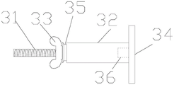
fig. 2 is a schematic structural view of the pre-buried sleeve of the present invention;
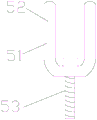
FIG. 3 is a schematic structural view of the U-shaped pull ring of the present invention;
fig. 4 is a schematic structural diagram of the movable positioning device of the present invention;
FIG. 5 is a schematic structural view of the linear beam body of the present invention;
FIG. 6 is a schematic structural view of the oblique angle beam body of the present invention;
FIG. 7 is a schematic structural view of the diagonal beam body of the present invention;
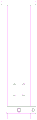
fig. 8 is a schematic structural view of the i-beam seat plate of the present invention.
In the figure, 1, a building structure beam, 2I-shaped steel beams, 3 embedded sleeves, 4 pull-up lug plates, 5U-shaped pull rings, 6 connecting hooks, 7 positive screw rods, 8 negative screw rods, 9 closed flower baskets, 10 thread protection sleeves, 11 movable positioning devices, 12 seat plates, 13 fixing holes, 31 mounting screw rods, 32 sleeves, 33 fastening nuts, 34 embedded sheets, 35 convex rubber rings, 36 nuts, 51 pull rings, 52 bolt holes, 53 fastening bolts, 111 positioning groove plates, 112 fastening screws and 113 pipe sleeves are arranged.
Detailed Description
As shown in fig. 1, 2, 3, 4 and 8, a pull rod type i-steel cantilever beam comprises a main body consisting of an i-steel beam 2, an embedded sleeve 3, a diagonal draw bar and a movable positioning device 11, wherein a seat plate 12 at one end of the i-steel beam 2 is fixedly connected with a building structure beam 1 through the embedded sleeve 3, two fixing holes 13 are arranged on the seat plate, one of the fixing holes is round and one of the fixing holes is long and round, the long and round fixing holes are conveniently connected with an embedded part, errors of the hole of the embedded part are prevented, an adjusting amount is reserved when a screw passes through, the embedded sleeve 3 consists of a mounting screw 31, a sleeve 32, a fastening nut 33 and an embedded sheet 34, the mounting screw 31 passes through the i-steel beam seat plate 12 to be connected with a nut 36 at the inner bottom of the sleeve, the embedded sheet 34 is arranged at the rear end of the sleeve, the fastening nut 33 is arranged on the mounting screw 31, a convex rubber ring, the connecting hook at one end of the diagonal draw bar is connected with the upper pulling lug plate at the top of the I-shaped steel beam, the connecting hook 6 at the other end of the diagonal draw bar is connected and fixed with the building structure beam 1 through a U-shaped pull ring 5, a pull ring 51 of the U-shaped pull ring 5 is provided with a bolt hole 52, a fastening bolt 53 passes through the bottom of the pull ring 51 to be connected with an embedded part of the building structure beam 1, the diagonal draw bar is composed of a positive lead screw 7 and a negative lead screw 8 through a closed type flower basket 9 at the middle part, two ends of the closed type flower basket 9 are respectively provided with corresponding positive and negative thread inner buckles, the diameter of the middle part of the closed type flower basket is larger than that of the inner buckles, the middle part of the closed type flower basket is provided with a round hole for the insertion of the fastening bar, the upper and lower ends of the closed type flower basket are respectively provided with a thread, thereby the joint is bent on the I-shaped girder steel downwards to positioning channel plate 111 one end, and the positioning channel plate other end is bent and is connected fixedly through fastening screw 112 with the I-shaped girder steel, and pipe box 113 sets up on the positioning channel plate. As shown in fig. 5, 6 and 7, the i-shaped steel beam is a straight beam body or a bevel beam body or a diagonal beam body to adapt to the beam surfaces of the building structures with different shapes.
The utility model discloses pull rod formula I-steel cantilever beam is when cast-in-place major structure roof beam, through pre-buried purpose-built-in fitting, treats the exterior sheathing and demolishs the back, fixes the I-steel cantilever beam installation in the structure roof beam outside through external high-strength nut, connects cantilever beam outer end otic placode through pull rod assembly one end, and the other end passes through U type pull ring and connects pre-buried subassembly. The movable positioning device on the I-shaped steel beam is used for fixing the steel pipes of the scaffold, and the length of the pull rod can be adjusted at any time by the diagonal draw bar so as to ensure the stability of the scaffold body. And the turnover number of times is greater than traditional wire rope far away, and detachable connections structure is adopted with building main structure to oblique pull rod upper end, and the after is demolishd to the outrigger, withdraws from the ears pull ring, alright whitewash, tiling, but the end process high-efficient operation, and the diameter of the lead screw protective sheath laminating of oblique pull rod prevents effectively that the concrete from falling to glue on adjusting the lead screw.
Claims (6)
1. A pull rod type I-steel cantilever beam is characterized in that a main body comprises an I-steel beam, an embedded sleeve, a diagonal draw bar and a movable positioning device, a seat plate at one end of the I-steel beam is fixedly connected with a building structure beam through the embedded sleeve, the embedded sleeve comprises an installation screw, a sleeve, a fastening nut and an embedded sheet, the installation screw penetrates through the seat plate of the I-steel beam and is connected with the nut at the bottom in the sleeve, the embedded sheet is arranged at the rear end of the sleeve, the fastening nut is arranged on the installation screw, a connecting hook at one end of the diagonal draw bar is connected with an upper pull lug plate at the top of the I-steel beam, a connecting hook at the other end of the diagonal draw bar is fixedly connected with the building structure beam through a U-shaped pull ring, a bolt hole is formed in the pull ring of the U-shaped pull ring, the fastening bolt penetrates through the bottom of the pull ring and is connected with an embedded part of the building structure beam, the, the movable positioning device is movably arranged at the end part of the I-shaped steel beam and consists of a positioning groove plate, fastening screws and a pipe sleeve, one end of the positioning groove plate is bent downwards and clamped on the I-shaped steel beam, the other end of the positioning groove plate is bent and fixed with the I-shaped steel beam through the fastening screws, and the pipe sleeve is arranged on the positioning groove plate.
2. The pull rod type i-steel cantilever beam of claim 1, wherein the mounting screw of the pre-embedded sleeve is provided with a convex rubber ring, and the convex rubber ring is matched with the sleeve.
3. The tie rod type i-steel cantilever beam of claim 1, wherein the diameter of the middle part of the closed type basket is larger than that of the inner buckling part, and a round hole is arranged in the middle of the closed type basket.
4. The tie rod type i-steel cantilever beam of claim 1, wherein the upper and lower ends of the closed type flower basket are respectively provided with a thread tooth protective sleeve.
5. The tie rod i-beam suspension according to claim 1, wherein the i-beam seat plate has two attachment holes, a circular and an oblong.
6. The tie rod i-beam cantilever according to claim 1, wherein the i-beam is a straight beam body or a diagonal beam body.
Priority Applications (1)
| Application Number | Priority Date | Filing Date | Title |
|---|---|---|---|
| CN202022127065.6U CN213268820U (en) | 2020-09-25 | 2020-09-25 | Pull rod type I-steel cantilever beam |
Applications Claiming Priority (1)
| Application Number | Priority Date | Filing Date | Title |
|---|---|---|---|
| CN202022127065.6U CN213268820U (en) | 2020-09-25 | 2020-09-25 | Pull rod type I-steel cantilever beam |
Publications (1)
| Publication Number | Publication Date |
|---|---|
| CN213268820U true CN213268820U (en) | 2021-05-25 |
Family
ID=75945105
Family Applications (1)
| Application Number | Title | Priority Date | Filing Date |
|---|---|---|---|
| CN202022127065.6U Active CN213268820U (en) | 2020-09-25 | 2020-09-25 | Pull rod type I-steel cantilever beam |
Country Status (1)
| Country | Link |
|---|---|
| CN (1) | CN213268820U (en) |
Cited By (2)
| Publication number | Priority date | Publication date | Assignee | Title |
|---|---|---|---|---|
| CN113404277A (en) * | 2021-07-15 | 2021-09-17 | 中建八局西南建设工程有限公司 | Elasticity-adjustable cantilever beam assembly and construction method thereof |
| CN115949228A (en) * | 2023-02-03 | 2023-04-11 | 中国核工业中原建设有限公司 | Upper pull rod scaffold with controllable tensioning and convenient selective examination |
-
2020
- 2020-09-25 CN CN202022127065.6U patent/CN213268820U/en active Active
Cited By (2)
| Publication number | Priority date | Publication date | Assignee | Title |
|---|---|---|---|---|
| CN113404277A (en) * | 2021-07-15 | 2021-09-17 | 中建八局西南建设工程有限公司 | Elasticity-adjustable cantilever beam assembly and construction method thereof |
| CN115949228A (en) * | 2023-02-03 | 2023-04-11 | 中国核工业中原建设有限公司 | Upper pull rod scaffold with controllable tensioning and convenient selective examination |
Similar Documents
| Publication | Publication Date | Title |
|---|---|---|
| CN108643544B (en) | High-altitude overhanging construction platform support system and construction method | |
| CN110805257B (en) | Flower basket overhanging type section steel bearing beam structure and construction method | |
| CN213268820U (en) | Pull rod type I-steel cantilever beam | |
| CN213329955U (en) | Flower basket diagonal rod type overhanging scaffold | |
| CN211736298U (en) | Double-rod diagonal cantilever scaffold | |
| CN212613769U (en) | Outer wall formwork reinforcing bracket at connecting position of shear wall floors | |
| CN111236621A (en) | Fixing system for beam-side embedded overhanging scaffold | |
| CN214195484U (en) | All-steel attached lifting scaffold | |
| CN116136122A (en) | Integrated attached type inclined lifting climbing frame system and use method thereof | |
| CN205348761U (en) | Basement does not have reinforced structure of no basic lift of installation on back board | |
| CN203452375U (en) | Hydraulic self-jacking oblique creeping formwork | |
| CN111827648A (en) | Construction device and method for down-supporting type overhanging scaffold | |
| CN111236603B (en) | Comprehensive construction method for steel plate mesh overhanging scaffold | |
| CN104989092B (en) | A kind of construction method of high-altitude overhanging superposed type steel truss bearing platform | |
| CN206753017U (en) | A kind of pull-back cable Superimposed fastener | |
| CN111519891A (en) | Anchor ring buckling type rigid outer frame wall connecting piece and construction method thereof | |
| CN203499259U (en) | Tool type cantilevered unloading platform | |
| CN212428008U (en) | Lower supporting type overhanging scaffold construction device | |
| CN212406038U (en) | Lower hanging construction platform module of high-altitude large-cantilever steel roof truss | |
| CN209742342U (en) | Climbing formula scaffold frame support increases subassembly | |
| CN204715720U (en) | The attachment supporting arrangement of the attachment type raise scaffold outside the building section of receipts within the walls | |
| CN114658214A (en) | High-rise building disc buckle type high-altitude large-cantilever support frame support and anchor pressing integrated construction method | |
| CN111764623A (en) | Lower hanging construction platform module of high-altitude large-cantilever steel roof truss and construction method | |
| CN201730306U (en) | Light-weight scaffold | |
| CN218668474U (en) | Basket type overhanging bearing frame |
Legal Events
| Date | Code | Title | Description |
|---|---|---|---|
| GR01 | Patent grant | ||
| GR01 | Patent grant |