CN213260361U - Vertical glass drilling machine - Google Patents
Vertical glass drilling machine Download PDFInfo
- Publication number
- CN213260361U CN213260361U CN202021998270.3U CN202021998270U CN213260361U CN 213260361 U CN213260361 U CN 213260361U CN 202021998270 U CN202021998270 U CN 202021998270U CN 213260361 U CN213260361 U CN 213260361U
- Authority
- CN
- China
- Prior art keywords
- sliding
- clamp
- assembly
- fixed
- seat
- Prior art date
- Legal status (The legal status is an assumption and is not a legal conclusion. Google has not performed a legal analysis and makes no representation as to the accuracy of the status listed.)
- Active
Links
Images


Landscapes
- Re-Forming, After-Treatment, Cutting And Transporting Of Glass Products (AREA)
- Processing Of Stones Or Stones Resemblance Materials (AREA)
Abstract
The utility model discloses a vertical glass drilling machine, which comprises a frame component, the top surface middle part of frame subassembly is along horizontal vertical being fixed with and is used for erectting along horizontal clamping glass's anchor clamps subassembly, both sides all are provided with a plurality of sliding plate subassembly, every around the anchor clamps subassembly the top surface of sliding plate subassembly all is fixed with the sliding seat subassembly, and same horizontal sliding seat subassembly mirror symmetry, every the top of sliding seat subassembly all be fixed with can to the drill bit subassembly that anchor clamps subassembly longitudinal movement is close to drilling. Has the advantages that: the utility model discloses constitute by sliding plate subassembly, frame subassembly, sliding seat subassembly, drill bit subassembly and anchor clamps subassembly etc. overall structure is compact simple, and operation process is simple easily goes up the hand, has reduced the technical degree requirement to operating the workman, accords with batch volume rapid tooling glass's use needs, is favorable to on a large scale popularization and production.
Description
Technical Field
The utility model relates to a glass processing equipment field, concretely relates to vertical glass drilling machine.
Background
The glass drilling machine is a machine specially used for glass drilling, a discrete glass drilling machine and a horizontal glass drilling machine, the vertical glass drilling machine is automatically controlled by a PLC (programmable logic controller), only glass needs to be placed on a conveying belt during operation, drilling position data is input, a button is started, all hole sites are drilled after automatic positioning, automatic stop is performed after work is completed, the drilling efficiency is high, the hole sites are accurate, the glass drilling machine is suitable for processing of building glass and furniture glass, the structure of the existing vertical glass drilling machine is complex and not easy to operate when the vertical glass drilling machine is designed, the requirement on the technical degree of an operator is high, and the glass drilling machine does not meet the use requirement of rapidly processing glass in.
SUMMERY OF THE UTILITY MODEL
The utility model aims at providing a vertical glass drilling machine just lies in solving above-mentioned problem and comprises sliding plate subassembly, frame subassembly, sliding seat subassembly, drill bit subassembly and anchor clamps subassembly etc. and overall structure is compact simple, and operation process is simple easily to be handed, has reduced the technical degree requirement to operating the workman, sees the explanation below in detail.
In order to achieve the above purpose, the utility model provides a following technical scheme:
the utility model provides a vertical glass drilling machine, including the frame subassembly, the top surface middle part of frame subassembly is fixed with along horizontal vertical the anchor clamps subassembly that is used for erectting along horizontal clamping glass, both sides all are provided with a plurality of sliding plate subassemblies around the anchor clamps subassembly, the top surface of each sliding plate subassembly all is fixed with the sliding seat subassembly, and the same horizontal sliding seat subassembly mirror symmetry, the top of each sliding seat subassembly all is fixed with can be to the drill bit subassembly that the anchor clamps subassembly longitudinal movement is close to the drilling;
the sliding plate assembly is matched with the rack assembly in a transverse sliding mode, a first roller screw pair is arranged on the lower portion of the sliding plate assembly and used for driving the sliding seat assembly to transversely move on the top surface of the rack assembly, meanwhile, the outer sides, far away from each other, of the sliding plate assemblies in the same transverse direction are connected with drag chain bodies, the end portions, close to each other, of the drag chain assemblies are fixed to the middle of the top surface of the rack assembly, and therefore the sliding seat assembly is dragged to transversely move on the top surface of the rack assembly through the drag chain assemblies.
By adopting the vertical glass drilling machine, in the using process, the glass conveyed by the external conveying belt is vertically clamped along the transverse direction by the clamp assembly, then the sliding seat assembly is driven to transversely move on the top surface of the rack assembly by the plurality of sliding plate assemblies on the two sides of the clamp assembly, the drill bit assembly is driven to move transversely to adjust the drilling position of the glass, the sliding plate assembly stops moving transversely after the drill bit assembly is adjusted in place, then the drill bit assembly is longitudinally fed to be close to the glass and to drill the glass, waste core materials after drilling fall to the lower portion of the drill bit assembly and are discharged from the rack assembly.
Preferably, the rack assembly comprises a base and an electric cabinet body, the base is of a welded frame structure, the electric cabinet body for control is embedded in the front of the base, a plurality of linear guide rails I are transversely fixed on the top surface of the base, the linear guide rails I correspond to the sliding plate assemblies one by one and are in transverse sliding fit, and therefore the sliding base can transversely move along the corresponding linear guide rails I.
Preferably, a material receiving groove used for receiving the core material of the drilled hole is transversely arranged in the base, and the outer end of the material receiving groove extends out of the outer side of the base.
Preferably, the sliding plate assembly comprises a sliding base plate, a fixed seat and a limiting seat, wherein the sliding base plate is in sliding fit with the linear guide rail I, the sliding seat assembly is fixed on the top surface of the sliding base plate, the proximity switches are fixed on the outward side surfaces of the sliding base plate through the fixed seat, and the limiting seat is fixed on the outer side of the linear guide rail I and is used for limiting the transverse moving stroke of the sliding plate assembly in cooperation with the proximity switches.
Preferably, the sliding seat assembly comprises a sliding seat plate and a sliding motor seat, the sliding seat plate is fixed to the top surface of the sliding base plate, the side surfaces, far away from each other, of the sliding seat plate are fixedly connected with the tow chain body through tow chain supports, a second ball screw pair and a second linear guide rail are arranged on the top surface of the sliding seat plate along the longitudinal direction, the sliding motor seat is fixed to the top surface of the sliding seat plate, and a three-phase aluminum shell motor is fixed to the top surface of the sliding motor seat and used for driving the second ball screw pair to move so that the drill bit assembly can move longitudinally along the second linear guide rail to be close to the drill hole of the clamp assembly.
Preferably, an outer shield for protecting the sliding seat assembly and the drill bit assembly is fixed on the periphery of the top surface of the sliding seat plate in a covering mode.
Preferably, the fixture assembly comprises two fixture seats and two fixture guide rods, the two fixture seats are respectively fixed at two ends of the top surface of the rack assembly in the same transverse direction, a moving seat is arranged in front of the upper portion of each fixture seat, the two fixture guide rods are transversely fixed between the two fixture seats and between the two moving seats, a plurality of fixture press plates are slidably matched on the vertically overlapped fixture guide rods, the fixture press plates are longitudinally and mutually matched to clamp the vertical glass, tensioning cylinders longitudinally arranged at two ends of each fixture seat are fixed, each tensioning cylinder is longitudinally provided with a pull rod capable of being longitudinally pulled, and the other end of each pull rod is connected with the moving seat, so that the moving seat is tensioned by the tensioning cylinders in a manner of driving the pull rods to longitudinally extend and retract to be close to the fixture seats and vertically clamp the glass through the fixture press plates mutually matched, the equal level of two outside top surfaces of anchor clamps seat is fixed with adjusting baffle, adjusting baffle's the equal vertical rotation in middle part is connected with adjusting screw, adjusting screw's bottom meshing has anchor clamps locking plate, two link together through the connecting rod between the lower part outside of anchor clamps locking plate, just the middle part level of connecting rod is fixed with a plurality of and is used for the bearing to erect glass's anchor clamps layer board.
Preferably, the side of the clamp pressing plate far away from each other is provided with a clamp positioning block, the clamp positioning block is in sliding fit with the clamp guide rod, the pull rod is connected with the moving seat through a linear bearing, and the adjusting screw rod is connected with the adjusting baffle through a thrust ball bearing.
Preferably, the top ends of the adjusting screws are fixed with adjusting hand wheels, and the connecting rods are aluminum profiles.
Preferably, baffles for protection are arranged on the periphery of the drag chain body, the baffles are fixed on the outer side of the rack assembly, organ covers for protection and isolation are arranged on two sides of the sliding plate assembly, and end covers are fixed on the outward end faces of the organ covers in a sealed mode.
Has the advantages that: the utility model discloses constitute by sliding plate subassembly, frame subassembly, sliding seat subassembly, drill bit subassembly and anchor clamps subassembly etc. overall structure is compact simple, and operation process is simple easily goes up the hand, has reduced the technical degree requirement to operating the workman, accords with batch volume rapid tooling glass's use needs, is favorable to on a large scale popularization and production.
Drawings
In order to more clearly illustrate the embodiments of the present invention or the technical solutions in the prior art, the drawings used in the description of the embodiments or the prior art will be briefly described below, it is obvious that the drawings in the following description are only some embodiments of the present invention, and for those skilled in the art, other drawings can be obtained according to these drawings without creative efforts.
Fig. 1 is a front view of the present invention;
figure 2 is a top view of the present invention from figure 1;
figure 3 is a back view of figure 1 of the present invention;
figure 4 is a right side view of the present invention from figure 1.
The reference numerals are explained below:
1. a sliding plate assembly; 101. a sliding substrate; 102. a fixed seat; 103. a proximity switch; 104. a limiting seat; 2. a rack assembly; 201. a machine base; 202. an electric cabinet body; 203. a material receiving groove; 204. a first linear guide rail; 3. a sliding seat assembly; 301. an outer shroud; 302. a ball screw pair II; 303. a second linear guide rail; 304. a tow chain support; 305. a slide seat plate; 306. a three-phase aluminum-shell motor; 307. a sliding motor base; 4. a drag chain body; 5. a baffle plate; 6. a first ball screw pair; 7. a clamp assembly; 701. A pull rod; 702. tensioning the cylinder; 703. a clamp positioning block; 704. a movable seat; 705. a connecting rod; 706. a clamp pallet; 707. adjusting a hand wheel; 708. adjusting the screw rod; 709. adjusting the baffle; 7010. A clamp locking plate; 7011. a clamp seat; 7012. pressing a clamp plate; 7013. a clamp guide rod; 8. a drill bit assembly; 9. an organ cover; 901. and (4) end covers.
Detailed Description
In order to make the objects, technical solutions and advantages of the present invention clearer, the technical solutions of the present invention will be described in detail below. It is to be understood that the embodiments described are only some embodiments of the invention, and not all embodiments. Based on the embodiments of the present invention, all other embodiments obtained by a person skilled in the art without creative efforts belong to the protection scope of the present invention.
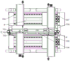
Referring to fig. 1-4, the utility model provides a vertical glass drilling machine, including frame subassembly 2, frame subassembly 2's top surface middle part is along horizontal vertical being fixed with be used for erectting along horizontal clamping glass's anchor clamps subassembly 7, both sides all are provided with a plurality of sliding plate subassembly 1 around anchor clamps subassembly 7, every sliding plate subassembly 1's top surface all is fixed with sliding seat subassembly 3, and same horizontal sliding seat subassembly 3 mirror symmetry, every sliding seat subassembly 3's top all is fixed with can to anchor clamps subassembly 7 longitudinal movement is close to the drill bit subassembly 8 of drilling. The sliding plate assembly 1 is in transverse sliding fit with the rack assembly 2, a first roller screw pair is arranged on the lower portion of the sliding plate assembly 1 and used for driving the sliding seat assembly 3 to transversely move on the top surface of the rack assembly 2, meanwhile, drag chain bodies 4 are connected to the outer sides, far away from each other, of the sliding plate assembly 1 in the same transverse direction, the end portions, close to each other, of the drag chain assemblies are fixed to the middle portion of the top surface of the rack assembly 2, and therefore the sliding seat assembly 3 is dragged to transversely move on the top surface of the rack assembly 2 through the drag chain assemblies.
As a preferable scheme of the present invention, the rack assembly 2 includes a base 201 and an electric cabinet body 202, the base 201 is a welded frame structure, the front part of the base 201 is embedded with the electric cabinet body 202 for control, a plurality of linear guide rails 204 are fixed on the top surface of the base 201 along the transverse direction, the linear guide rails 204 are in one-to-one correspondence with the sliding plate assemblies 1 and are in sliding fit along the transverse direction, thereby enabling the sliding seat to transversely move along the corresponding linear guide rail I204, so that the arrangement is convenient for realizing the electric control of each part through the electric cabinet body 202, a material receiving groove 203 for receiving the core material of the drilled hole is transversely arranged in the base 201, and the outer end of the material receiving groove 203 extends out of the outer side of the machine base 201, so that the waste core materials generated by drilling can conveniently fall into the material receiving groove 203 and then roll to the outside of a discharge value.
The sliding plate assembly 1 comprises a sliding base plate 101, a fixed seat 102 and a limiting seat 104 which are mutually matched with a first linear guide rail 204 in a sliding mode, the sliding seat assembly 3 is fixed on the top surface of the sliding base plate 101, the outward side surface of the sliding base plate 101 is fixed with a proximity switch 103 through the fixed seat 102, and the limiting seat 104 is fixed on the outer side of the first linear guide rail 204 and used for being matched with the proximity switch 103 to limit the transverse moving stroke of the sliding plate assembly 1.
The sliding seat assembly 3 comprises a sliding seat plate 305 and a sliding motor base 307, the sliding seat plate 305 is fixed on the top surface of the sliding base plate 101, the side surfaces, far away from each other, of the sliding seat plate 305 are fixedly connected with the towing chain body 4 through a towing chain support 304, the top surface of the sliding seat plate 305 is provided with a second ball screw pair 302 and a second linear guide rail 303 along the longitudinal direction, the top surface of the sliding seat plate 305 is fixed with the sliding motor base 307, the top surface of the sliding motor base 307 is fixed with a three-phase aluminum shell motor 306 for driving the second ball screw pair 302 to act so that the drill bit assembly 8 can longitudinally move along the second linear guide rail 303 to be close to the clamp assembly 7 for drilling, the arrangement is convenient for driving the drill bit assembly 8 to longitudinally move through the sliding seat assembly 3 to be close to the vertical glass for feeding and drilling, the periphery of the top surface of the sliding seat plate 305 is coated and fixed with an outer protective cover 301 for, so arranged, dust-proof and isolation protection of the sliding seat assembly 3 and the drill bit assembly 8 is facilitated through the outer shield 301.
The clamp component 7 comprises two clamp seats 7011 and two clamp guide rods 7013, the two clamp seats 7011 are respectively fixed at two ends of the top surface of the rack component 2 in the same transverse direction, a moving seat 704 is arranged in front of the upper portion of each clamp seat 7011, two clamp seats 7011 and two moving seats 704 are transversely fixed with two clamp guide rods 7013, the clamp guide rods 7013 vertically overlapped are matched with a plurality of clamp pressing plates 7012 in a sliding mode, the clamp pressing plates 7012 are longitudinally opposite to each other to clamp vertical glass, tensioning cylinders 702 longitudinally arranged are fixed at two ends of each clamp seat 7011, the tensioning cylinders 702 are longitudinally provided with pull rods 701 capable of being longitudinally pulled, the other ends of the pull rods 701 are connected with the moving seats, and the moving seats 704 are tensioned in a mode that the tensioning cylinders 702 drive the pull rods 701 to longitudinally stretch and retract so that the moving seats 704 are close to the clamp seats 7011 and are tensioned in a mode that the pull rods 701 are longitudinally stretched and retracted by the tensioning cylinders 702 The mutually-matched clamp pressing plates 7012 vertically clamp the glass, the top surfaces of two outer sides of the clamp base 7011 are horizontally fixed with adjusting baffle plates 709, the middle parts of the adjusting baffle plates 709 are vertically and rotatably connected with adjusting screw rods 708, the bottom ends of the adjusting screw rods 708 are meshed with clamp locking plates 7010, the outer sides of the lower parts of the two clamp locking plates 7010 are connected together through connecting rods 705, a plurality of clamp supporting plates 706 used for supporting the vertical glass are horizontally fixed at the middle parts of the connecting rods 705, the arrangement is convenient for tensioning the moving base 704 to be close to the clamp base 7011 in a manner that the tensioning cylinder 702 drives a pull rod 701 to longitudinally stretch and retract, the glass is vertically clamped through the mutually-matched clamp pressing plates 7012, the supported glass is locked and locked in a manner that the clamp supporting plates 706 are driven by the adjusting screw rods 708 to ascend and descend, and the clamp positioning blocks 703 are arranged on the sides of the clamp pressing plates, and the clamp positioning block 703 is in sliding fit with the clamp guide rod 7013, the pull rod 701 is connected with the moving seat 704 through a linear bearing, and the adjusting screw 708 is connected with the adjusting baffle 709 through a thrust ball bearing, so that the pull rod 701 can drive the moving seat 704 to smoothly approach or leave the clamp seat 7011, and meanwhile, the adjusting screw 708 can smoothly rotate horizontally.
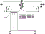
The top ends of the adjusting screws 708 are all fixed with adjusting hand wheels 707, so that the adjusting screws 708 can be conveniently rotated by applying force in a manner of holding the adjusting hand wheels 707 by hands, the connecting rod 705 is an aluminum profile, so arranged, the connecting rod 705 has a good service life, the periphery of the drag chain body 4 is provided with a baffle 5 for protection, and the baffle 5 is fixed at the outer side of the frame component 2, so that the action of the drag chain body 4 is restrained by the baffle 5, thereby facilitating the drag chain body 4 to drive the drill bit component 8 to rapidly and transversely move, wherein the two sides of the sliding plate component 1 are respectively provided with an organ cover 9 for protection and isolation, and the end faces, which face outwards, of the organ covers 9 are all sealed and fixed with end covers 901, so that the stable isolation and protection of the sliding plate component 1 can be conveniently carried out through the organ covers 9.
By adopting the structure, in the using process, the glass conveyed by an external conveying belt is vertically clamped along the transverse direction by the clamp assembly 7, then the sliding seat assembly 3 is driven to transversely move on the top surface of the rack assembly 2 by the plurality of sliding plate assemblies 1 at the two sides of the clamp assembly 7, the drill bit assembly 8 is driven to move transversely to adjust the drilling position of the glass, the sliding plate assembly 1 stops moving transversely after the drill bit assembly 8 is adjusted in place, then the drill bit assembly 8 is longitudinally fed to be close to the glass and reach the glass drilling, waste core materials after drilling fall to the lower portion, the waste core materials are discharged from the rack assembly 2, the whole device is compact and simple in structure, the operation process is simple and easy to operate, the technical degree requirement on operators is lowered, the use requirement of batch rapid glass processing is met, and the device is beneficial to large-scale popularization and production.
The above description is only for the specific embodiments of the present invention, but the protection scope of the present invention is not limited thereto, and any person skilled in the art can easily think of the changes or substitutions within the technical scope of the present invention, and all should be covered within the protection scope of the present invention. Therefore, the protection scope of the present invention shall be subject to the protection scope of the claims.
Claims (10)
1. A vertical glass drilling machine, includes frame subassembly (2), its characterized in that: a clamp assembly (7) for vertically clamping glass in the transverse direction is vertically fixed in the middle of the top surface of the rack assembly (2) in the transverse direction, a plurality of sliding plate assemblies (1) are arranged on the front side and the rear side of the clamp assembly (7), a sliding seat assembly (3) is fixed on the top surface of each sliding plate assembly (1), the sliding seat assemblies (3) in the same transverse direction are in mirror symmetry, and a drill bit assembly (8) capable of longitudinally moving towards the clamp assembly (7) and approaching to a drill hole is fixed on the top of each sliding seat assembly (3);
the sliding plate assembly (1) is in transverse sliding fit with the rack assembly (2), a first roller screw pair is arranged on the lower portion of the sliding plate assembly (1) and used for driving the sliding seat assembly (3) to transversely move on the top surface of the rack assembly (2), meanwhile, drag chain bodies (4) are connected to the outer sides, far away from each other, of the sliding plate assembly (1) in the same transverse direction, the end portions, close to each other, of the drag chain assemblies are fixed to the middle of the top surface of the rack assembly (2), and therefore the sliding seat assembly (3) is dragged to transversely move on the top surface of the rack assembly (2) through the drag chain assemblies.
2. The vertical glass drilling machine according to claim 1, wherein: frame subassembly (2) are including frame (201) and electric cabinet body (202), frame (201) are welding frame construction, the front portion of frame (201) is inlayed and is equipped with and is used for controlling electric cabinet body (202), the top surface of frame (201) is along transversely being fixed with many linear guide one (204), linear guide one (204) with sliding plate subassembly (1) one-to-one and along transverse sliding fit, so can make the sliding seat along corresponding linear guide one (204) lateral shifting.
3. A vertical glass drilling machine according to claim 2, characterized in that: the drill core material receiving device is characterized in that a material receiving groove (203) used for receiving drill core materials is transversely arranged in the base (201), and the outer end of the material receiving groove (203) extends out of the outer side of the base (201).
4. A vertical glass drilling machine according to claim 2 or 3, characterized in that: the sliding plate assembly (1) comprises a sliding base plate (101), a fixed seat (102) and a limiting seat (104), wherein the sliding base plate (101) is in sliding fit with a linear guide rail I (204), the sliding seat assembly (3) is fixed on the top surface of the sliding base plate (101), proximity switches (103) are fixed on the outward side surfaces of the sliding base plate (101) through the fixed seat (102), and the limiting seat (104) is fixed on the outer side of the linear guide rail I (204) and is used for being matched with the proximity switches (103) to limit the transverse moving stroke of the sliding plate assembly (1).
5. The vertical glass drilling machine according to claim 4, wherein: the sliding seat assembly (3) comprises a sliding seat plate (305) and a sliding motor base (307), the sliding seat plate (305) is fixed to the top surface of the sliding base plate (101), the side surfaces, far away from each other, of the sliding seat plate (305) are fixedly connected with the drag chain body (4) through a drag chain support (304), the top surface of the sliding seat plate (305) is provided with a second longitudinal ball screw pair (302) and a second linear guide rail (303), the top surface of the sliding seat plate (305) is fixed with the sliding motor base (307), and the top surface of the sliding motor base (307) is fixed with a three-phase aluminum shell motor (306) for driving the second ball screw pair (302) to move so that the drill bit assembly (8) can move longitudinally along the second linear guide rail (303) to be close to the drill hole of the clamp assembly (7).
6. The vertical glass drilling machine according to claim 5, wherein: and an outer shield (301) used for protecting the sliding seat assembly (3) and the drill bit assembly (8) is fixedly wrapped on the periphery of the top surface of the sliding seat plate (305).
7. A vertical glass drilling machine according to claim 5 or 6, characterized in that: the clamp component (7) comprises two clamp seats (7011) and clamp guide rods (7013), the two clamp seats (7011) are respectively fixed at two ends of the top surface of the rack component (2) in the same transverse direction, a moving seat (704) is arranged in front of the upper portion of each clamp seat (7011), two clamp seats (7011) and two moving seats (704) are transversely fixed with two clamp guide rods (7013), the clamp guide rods (7013) vertically overlapped are matched with a plurality of clamp pressing plates (7012) in a sliding manner, the clamp pressing plates (7012) are longitudinally and mutually matched for clamping vertical glass, tensioning cylinders (702) longitudinally arranged at two end portions of each clamp seat (7011) are fixed, the tensioning cylinders (702) are longitudinally provided with pull rods (701) capable of being longitudinally pulled, the other end of the pull rod (701) is connected with the moving seat (704), the pulling cylinder (702) is used for driving the pull rod (701) to longitudinally stretch in a stretching mode, the moving seat (704) is close to the clamp seat (7011) and is used for vertically clamping glass through the clamp pressing plates (7012) which are mutually contrasted, adjusting baffles (709) are horizontally fixed on the top surfaces of the two outer sides of the clamp seat (7011), the middle of each adjusting baffle (709) is vertically and rotatably connected with an adjusting screw (708), clamp locking plates (7010) are meshed at the bottom ends of the adjusting screws (708), the two clamp locking plates (7010) are connected together through a connecting rod (705), and a plurality of clamp supporting plates (706) used for supporting and erecting the glass are horizontally fixed in the middle of the connecting rod (705).
8. The vertical glass drilling machine according to claim 7, wherein: the clamp is characterized in that clamp positioning blocks (703) are arranged on sides, away from each other, of the clamp pressing plate (7012), the clamp positioning blocks (703) are in sliding fit with the clamp guide rod (7013), the pull rod (701) is connected with the moving seat (704) through a linear bearing, and the adjusting screw rod (708) is connected with the adjusting baffle (709) through a thrust ball bearing.
9. The vertical glass drilling machine according to claim 8, wherein: adjusting hand wheels (707) are fixed at the top ends of the adjusting screws (708), and the connecting rod (705) is an aluminum profile.
10. A vertical glass drilling machine according to claim 8 or 9, characterized in that: the drag chain is characterized in that baffles (5) used for protection are arranged on the periphery of the drag chain body (4), the baffles (5) are fixed on the outer side of the rack assembly (2), organ covers (9) used for protection and isolation are arranged on two sides of the sliding plate assembly (1), and end covers (901) are fixed on the outward end faces of the organ covers (9) in a sealed mode.
Priority Applications (1)
| Application Number | Priority Date | Filing Date | Title |
|---|---|---|---|
| CN202021998270.3U CN213260361U (en) | 2020-09-14 | 2020-09-14 | Vertical glass drilling machine |
Applications Claiming Priority (1)
| Application Number | Priority Date | Filing Date | Title |
|---|---|---|---|
| CN202021998270.3U CN213260361U (en) | 2020-09-14 | 2020-09-14 | Vertical glass drilling machine |
Publications (1)
| Publication Number | Publication Date |
|---|---|
| CN213260361U true CN213260361U (en) | 2021-05-25 |
Family
ID=75941177
Family Applications (1)
| Application Number | Title | Priority Date | Filing Date |
|---|---|---|---|
| CN202021998270.3U Active CN213260361U (en) | 2020-09-14 | 2020-09-14 | Vertical glass drilling machine |
Country Status (1)
| Country | Link |
|---|---|
| CN (1) | CN213260361U (en) |
-
2020
- 2020-09-14 CN CN202021998270.3U patent/CN213260361U/en active Active
Similar Documents
| Publication | Publication Date | Title |
|---|---|---|
| CN100579684C (en) | Bidirectional movement vertical type steel-bar automatic bending machine | |
| CN108581160B (en) | Automatic spot welder for corrugated oil tank of power transformer | |
| CN112548375A (en) | Automatic section bar feeding method for laser cutting machine | |
| CN114406782A (en) | Hydraulic mechanical claw for feeding | |
| CN210527583U (en) | Plate chain conveying equipment with tool | |
| CN108406004B (en) | Bolt chamfering device | |
| CN213260361U (en) | Vertical glass drilling machine | |
| CN212552544U (en) | Cylinder welding device | |
| CN211248396U (en) | Auto-parts drilling equipment with duplex position | |
| CN205497638U (en) | A advance and retreat material device for paper tube cutting | |
| CN214137857U (en) | Gold stamping device for vertebral body barrel | |
| CN110681995B (en) | Oven liner welding system and welding method | |
| CN210453075U (en) | Novel high-efficient numerical control cutting machine | |
| CN113001234A (en) | Lifting carrying robot for machine tool machining materials and using method thereof | |
| CN220838285U (en) | Steering gear rack double-sided tapping machine tool | |
| CN220864268U (en) | Edge banding equipment | |
| CN214816750U (en) | Rotary carbon fiber badminton racket drilling clamp | |
| CN215317315U (en) | Truss manipulator | |
| CN218319409U (en) | Equipment for continuous butt joint of materials | |
| CN220196530U (en) | Part machining cutting machine tool | |
| CN218840889U (en) | Material handling device | |
| CN215788478U (en) | Manipulator translation device for composite machining of multiple machine tools | |
| CN219483978U (en) | Synchronous double-end rotary shrinking machine for short materials | |
| CN216177856U (en) | Automatic large-scale work piece automatic weld equipment of loading | |
| CN218855766U (en) | Sawing machine lifting device |
Legal Events
| Date | Code | Title | Description |
|---|---|---|---|
| GR01 | Patent grant | ||
| GR01 | Patent grant |