CN213234571U - Lock body - Google Patents
Lock body Download PDFInfo
- Publication number
- CN213234571U CN213234571U CN202021262352.1U CN202021262352U CN213234571U CN 213234571 U CN213234571 U CN 213234571U CN 202021262352 U CN202021262352 U CN 202021262352U CN 213234571 U CN213234571 U CN 213234571U
- Authority
- CN
- China
- Prior art keywords
- piece
- linkage
- lock
- limiting
- safety
- Prior art date
- Legal status (The legal status is an assumption and is not a legal conclusion. Google has not performed a legal analysis and makes no representation as to the accuracy of the status listed.)
- Active
Links
Images


Landscapes
- Lock And Its Accessories (AREA)
Abstract
The utility model discloses a lock body, include: a lock case; the unlocking assembly comprises a linkage piece and a linkage reset piece, the linkage reset piece is used for driving the linkage piece to move to an upper locking position, the linkage piece is provided with a first sliding groove, and the first sliding groove comprises a limiting position; the safety assembly comprises a safety oblique tongue piece, a safety tongue reset piece, a limiting piece and a limiting reset piece, wherein the safety tongue reset piece is used for driving the safety oblique tongue piece to extend out of the lock shell, and the limiting piece is provided with a first bulge matched with the first sliding groove; when the linkage piece is in the unlocking position, the first bulge is over against the limiting position, and the safety latch piece extends out of the lock shell, the first bulge is positioned in the limiting position, and when the safety latch piece retracts into the lock shell, the limiting reset piece can drive the limiting piece to move to enable the first bulge to be separated from the limiting position; the square tongue piece, square tongue driving medium and linkage, square tongue piece sliding connection, the linkage passes through the square tongue driving medium and drives square tongue piece part and stretch out the lock shell, and this application can be locked fast to have good theftproof performance.
Description
Technical Field
The utility model relates to a tool to lock technical field, in particular to lock body.
Background
The lock body structure of the ordinary lock body with the quick-closing function is simpler, in order to realize the quick locking, the door lock is generally not provided with a dead bolt, only provided with a latch bolt, the latch bolt is easy to press into the lock shell, or a handle of the door is pulled by a thin small stick outside the door, so that the door is opened, and therefore, the anti-theft performance of the lock body with the quick locking function is poor; the lock body with high anti-theft performance is more complex in structure and locking process, generally comprises three or more lock tongues, and a user needs to control the square tongues to extend out of the lock body by a key after closing a door, so that the locking process is not convenient enough.
SUMMERY OF THE UTILITY MODEL
The utility model discloses aim at solving one of the technical problem that exists among the prior art at least. Therefore, the utility model provides a lock body can lock fast to have good theftproof performance.
According to the utility model discloses a lock body, include:
a lock case;
the unlocking assembly comprises a linkage piece and a linkage reset piece, the linkage piece is connected with the lock shell in a sliding mode, the linkage reset piece is connected with the linkage piece and used for driving the linkage piece to move to an upper locking position, the linkage piece is provided with a first sliding groove, and a limiting position is arranged in the first sliding groove;
the safety assembly comprises a safety oblique tongue piece, a safety tongue reset piece, a limiting piece and a limiting reset piece, wherein the safety oblique tongue piece and the limiting piece are respectively connected with the lock shell in a sliding mode, the safety tongue reset piece is abutted against the safety oblique tongue piece and used for driving the safety oblique tongue piece to extend out of the lock shell, the limiting reset piece is abutted against the limiting piece, and the limiting piece is provided with a first bulge matched with the first sliding groove; when the linkage piece is located at the unlocking position, the first bulge is over against the limiting position, and the safety latch bolt piece extends out of the lock shell, the safety latch bolt piece is abutted against the limiting piece, the first bulge is located in the limiting position, and when the safety latch bolt piece retracts into the lock shell, the limiting reset piece can drive the limiting piece to move, and the first bulge is separated from the limiting position;
the square tongue assembly comprises a square tongue piece and a square tongue transmission piece, the square tongue piece is slidably connected with the lock shell, the square tongue transmission piece is respectively connected with the linkage piece and the square tongue piece, and the linkage piece drives the square tongue piece to partially extend out of the lock shell through the square tongue transmission piece.
According to the utility model discloses lock body has following beneficial effect at least: in the door closing process, the safety latch bolt piece is pressed into the lock shell by the door frame, the linkage reset piece drives the linkage piece to move downwards, the linkage piece drives the square bolt piece to partially extend out of the lock shell through the square bolt transmission piece, so that the square bolt piece can be automatically popped out of the lock shell when the door is closed, and the door frame presses the safety latch bolt piece to keep the safety latch bolt piece in a state of retracting into the lock shell after the door is closed; after opening the door, the linkage removes to the position of unlocking, and insurance latch bolt spare stretches out the lock shell under the drive of insurance latch bolt piece that resets, and insurance latch bolt spare and stopper butt drive first arch and remove to the restriction position of first spout to the linkage position is fixed, and square bolt spare keeps the state of indentation lock shell, consequently the utility model discloses square bolt spare can auto-eject when closing the door, thereby realizes locking fast, and square bolt spare is difficult to be pried open, thereby the lock body has good theftproof performance.
According to some embodiments of the utility model, the subassembly of unblanking still includes the lock core piece, the lock core piece is equipped with the second arch, rotates the lock core piece, the second arch can with the linkage butt drives the linkage removes to the position of unblanking.
According to some embodiments of the utility model, the subassembly of unblanking still includes interior handle thumb wheel and handle piece that resets, interior handle thumb wheel with the lock shell rotates to be connected, handle piece that resets with interior handle thumb wheel is connected and is used for driving interior handle thumb wheel autogiration resets, the linkage be equipped with be used for with the first protruding axle of interior handle thumb wheel butt rotates interior handle thumb wheel can drive the linkage remove extremely the position of unblanking.
According to some embodiments of the invention, the inner handle thumb wheel is provided with a lever part for abutting against the first protruding shaft.
According to some embodiments of the utility model, still include bidirectional latch bolt spare and latch bolt piece that resets, bidirectional latch bolt spare with lock shell sliding connection, latch bolt piece that resets with the lock shell is connected, latch bolt piece that resets is used for driving bidirectional latch bolt spare part is stretched out the lock shell.
According to some embodiments of the present invention, the bidirectional latch member is provided with a second protruding shaft, the linkage member is provided with a second sliding groove, when the linkage member is in the unlocking position, the second protruding shaft faces the second sliding groove, and the second protruding shaft can be retracted into the second sliding groove; when the linkage piece is located in the upper locking state, the second protruding shaft and the second sliding groove are mutually staggered.
According to some embodiments of the utility model, the square tongue driving medium is equipped with third protruding axle, fourth protruding axle and fifth protruding axle, the linkage piece be equipped with third protruding axle complex third spout, the linkage piece still be equipped with fourth protruding axle complex fourth spout, the square tongue piece be equipped with fifth protruding axle complex fifth spout, the fifth spout is V type groove.
According to some embodiments of the utility model, the bidirectional oblique tongue piece is equipped with oblique tongue protruding axle, the lock shell be equipped with oblique tongue protruding axle complex oblique tongue spout.
According to some embodiments of the utility model, the linkage is equipped with the protruding axle of linkage, the lock shell be equipped with the protruding axle complex linkage spout of linkage.
According to some embodiments of the utility model, the stopper is equipped with the stopper protruding axle, the lock shell be equipped with stopper protruding axle complex stopper spout.
Additional aspects and advantages of the invention will be set forth in part in the description which follows and, in part, will be obvious from the description, or may be learned by practice of the invention.
Drawings
The above and/or additional aspects and advantages of the present invention will become apparent and readily appreciated from the following description of the embodiments, taken in conjunction with the accompanying drawings of which:
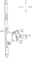
fig. 1 is a schematic view of an inside direction of a door in an unlocked state of a lock body according to an embodiment of the present invention;
fig. 2 is a schematic view of the lock body in an unlocked state according to the embodiment of the present invention;
fig. 3 is a three-dimensional structural view of the lock body in the door inside direction in the unlocking state according to the embodiment of the present invention;
fig. 4 is a three-dimensional structural view of a lock body with a linkage removed according to an embodiment of the present invention;
fig. 5 is a three-dimensional structural view of the lock body in the locking state according to the embodiment of the present invention;
figure 6 is a block diagram of one embodiment of a stop of a lock body according to an embodiment of the present invention;
figure 7 is a block diagram of one embodiment of a stop of a lock body according to an embodiment of the present invention;
figure 8 is a block diagram of one embodiment of a stop of a lock body according to an embodiment of the present invention;
fig. 9 is a structural diagram of a square tongue driving member and a square tongue member of a lock body according to an embodiment of the present invention;
figure 10 is a block diagram of the square tongue driving member, the square tongue member and the link member of the lock body according to the embodiment of the present invention;
fig. 11 is a structural view of a safety cross tongue member and a stopper member of a lock body according to an embodiment of the present invention;
fig. 12 is a schematic structural diagram of a lock case of a lock body according to an embodiment of the present invention.
A lock case 100, a latch bolt chute 110, a link chute 120,
A stopper sliding groove 130, a safety tongue sliding groove 140, a square tongue protruding shaft 150,
A safety oblique tongue piece 210, a safety tongue reset piece 211, a safety tongue protruding shaft 212,
A square tongue piece 220, a square tongue chute 221, a fifth chute 222,
A bidirectional latch piece 230, a latch piece resetting piece 231, a second convex shaft 232, a latch piece convex shaft 233,
A lock cylinder member 310, a second protrusion 311,
A linkage member 320, a linkage reset member 321, a first sliding chute 322, a stopper 3221, a limit position 3222,
A first convex shaft 323, a second chute 324, a linkage convex shaft 325,
A third slide groove 326, a fourth slide groove 327,
A square tongue transmission member 330, a third protruding shaft 331, a fourth protruding shaft 332, a fifth protruding shaft 333,
A stopper 340, a first bulge 341, a stopper reset 342, a stopper convex shaft 343,
An inner handle thumb wheel 350, a handle return 351, and a toggle member 352.
Detailed Description
Reference will now be made in detail to embodiments of the present invention, examples of which are illustrated in the accompanying drawings, wherein like reference numerals refer to the same or similar elements or elements having the same or similar function throughout. The embodiments described below with reference to the drawings are exemplary only for the purpose of explaining the present invention, and should not be construed as limiting the present invention.
In the description of the present invention, it should be understood that the orientation or positional relationship indicated, for example, up, down, left, right, etc., referred to the orientation description is based on the orientation or positional relationship shown in the drawings, and is only for convenience of description and simplification of description, and does not indicate or imply that the device or element referred to must have a specific orientation, be constructed and operated in a specific orientation, and thus, should not be construed as limiting the present invention.
In the description of the present invention, greater than, less than, exceeding, etc. are understood as not including the present numbers. If there is a description of the first, second, third, fourth and fifth only for the purpose of distinguishing between technical features, it is not to be understood as indicating or implying relative importance or implicitly indicating the number of technical features indicated or implicitly indicating the precedence of technical features indicated.
In the description of the present invention, unless there is an explicit limitation, the words such as setting, installation, connection, etc. should be understood in a broad sense, and those skilled in the art can reasonably determine the specific meanings of the above words in combination with the specific contents of the technical solution.
Referring to fig. 1-3, an embodiment of the present invention provides a lock body including:
a lock case 100;
the unlocking assembly comprises a linkage piece 320 and a linkage reset piece 321, the linkage piece 320 is slidably connected with the lock shell 100, the linkage reset piece 321 is connected with the linkage piece 320 and is used for driving the linkage piece 320 to move to an upper locking position, the linkage piece 320 is provided with a first sliding groove 322, and a limit position 3222 is arranged in the first sliding groove 322;
the safety assembly comprises a safety oblique tongue piece 210, a safety tongue reset piece 211, a limiting piece 340 and a limiting reset piece 342, wherein the safety oblique tongue piece 210 and the limiting piece 340 are respectively connected with the lock shell 100 in a sliding mode, the safety tongue reset piece 211 is abutted to the safety oblique tongue piece 210 and used for driving the safety oblique tongue piece 210 to extend out of the lock shell 100, the limiting reset piece 342 is abutted to the limiting piece 340, and the limiting piece 340 is provided with a first protrusion 341 matched with the first sliding groove 322; when the linkage member 320 is in the unlocking position, the first protrusion faces the limiting position 3222, and the safety latch 210 extends out of the lock case 100, the safety latch 210 abuts against the limiting member 340, the first protrusion 341 is located in the limiting position 3222, and when the safety latch 210 retracts into the lock case 100, the limiting reset member 342 can drive the limiting member 340 to move, and the first protrusion 341 is separated from the limiting position 3222;
the square tongue component comprises a square tongue piece 220 and a square tongue transmission piece 330, wherein the square tongue piece 220 is slidably connected with the lock shell 100, the square tongue transmission piece 330 is respectively connected with a linkage piece 320 and the square tongue piece 220, and the linkage piece 320 drives the square tongue piece 220 to partially extend out of the lock shell 100 through the square tongue transmission piece 330.
After the user closes the door, the dead bolt piece 220 will pop up automatically to lock automatically: fig. 1-4 show the unlocked state of the door lock, in which the linkage 320 is in the unlocked state, the safety latch 210 is kept partially extending out of the lock case 100 by the safety latch resetting element 211, the safety latch 210 abuts against the limiting element 340 and drives the limiting element 340 to move leftward, so that the first protrusion 341 moves to the limiting position 3222 of the first sliding slot 322, the position of the linkage 320 is fixed, the square latch 220 is kept retracted into the lock case 100 without automatically popping out of the lock case 100, referring to fig. 3 and 11, during the process of closing the door and the door frame, the door frame presses the safety latch 210 into the lock case 100, the safety latch 210 no longer abuts against the limiting element 340, and the limiting resetting element drives the limiting element 340 to move leftward to disengage the first protrusion 341 from the limiting position 3222 of the first sliding slot 322, so that the position of the linkage 320 is not fixed but can move upward and downward, and the linkage resetting element 321 drives the linkage 320 to move downward to the upper locking position, as shown in fig. 5, at this time, the link 320 is located in the locked state, the link 320 drives the square tongue piece 220 to move leftward through the square tongue transmission member 330, the square tongue piece 220 is automatically ejected out and partially extends out of the lock case 100, and the square tongue piece 220 is difficult to be pried, so the embodiment of the present invention can lock conveniently and quickly while ensuring the anti-theft performance.
Referring to fig. 1, in some embodiments, the safety tongue resetting member 211, the linkage resetting member 321, and the movement limiting resetting member 342 are in a spring, elastic piece, or elastic rope structure, in this embodiment, the movement limiting resetting member 342 is in a torsion spring structure, and both the safety tongue resetting member 211 and the linkage resetting member 321 are in a torsion spring structure.
Referring to fig. 1, a stopper 3221 is disposed at a left portion of the first sliding groove 322, a limit position 3222 is formed below the stopper 3221 and the first sliding groove 322, when the first protrusion 341 moves to the limit position 3222, a relative position between the link 320 and the stopper 340 in an up-and-down direction is fixed, the stopper 340 can only move left and right but cannot move up and down, so that the link 320 cannot move up and down, the square tongue 220 maintains a state of being retracted into the lock case 100, when the first protrusion 341 disengages from the limit position 3222, the link 320 can move up and down, and when the link 320 moves down, the first protrusion 341 can slide below the stopper 3221, in some embodiments, the shape of the stopper 3221 is an obtuse triangle, a right triangle, or an irregular triangle;
referring to fig. 6, in the present embodiment, the stopping member 3221 is shaped as an obtuse triangle, and a blunt edge of the stopping member 3221 coincides with the left side of the first sliding groove 322;
referring to fig. 7, in the present embodiment, the stopping member 3221 is shaped as a right triangle, and a right-angled side of the stopping member 3221 coincides with the left side of the first sliding groove 322;
referring to fig. 8, in the present embodiment, the shape of the stopping member 3221 is an irregular triangle, a first edge of the stopping member 3221 coincides with the left edge of the first sliding groove 322, an included angle between a second edge of the stopping member 3221 and the first edge is less than 90 degrees, and a third edge of the stopping member 3221 is an arc edge.
Referring to fig. 1 and 3, the unlocking assembly further includes a lock cylinder member 310, the lock cylinder member 310 is provided with a second protrusion 311, the lock cylinder member 310 is rotated, the second protrusion 311 can abut against the link member 320 and drive the link member 320 to move to the unlocking position, when a user opens the door with a key, when the lock cylinder member 310 rotates, the second protrusion 311 drives the link member 320 to move upward to the unlocking position, and the link member 320 drives the square tongue member 220 to move rightward through the square tongue transmission member 330, so that the square tongue member 220 retracts into the lock case 100.
Referring to fig. 1 and 3, the unlocking assembly further comprises an inner handle thumb wheel 350 and a handle resetting member 351, the inner handle thumb wheel 350 is rotatably connected with the lock case 100, the handle resetting member 351 is connected with the inner handle thumb wheel 350 and is used for driving the inner handle thumb wheel 350 to automatically rotate and reset, the linkage member 320 is provided with a first convex shaft 323 used for abutting against the inner handle thumb wheel 350, the linkage member 320 can be driven to move to the unlocking position by rotating the inner handle thumb wheel 350, and the handle resetting member 351 is connected with the lock case 100; the inner handle thumb wheel 350 is used to control the retraction of the pawl 220 into the lock housing 100, thereby unlocking: referring to fig. 2, the inner handle thumb wheel 350 is connected with the inner door handle, the user rotates the inner door handle counterclockwise, the inner handle thumb wheel 350 rotates counterclockwise and abuts against the first protruding shaft 323, the handle reset piece 351 is squeezed, the inner handle thumb wheel 350 drives the linkage piece 320 to move upward through the first protruding shaft 323, the linkage piece 320 drives the square tongue piece 220 to move rightward through the square tongue transmission piece 330, so that the square tongue piece 220 retracts into the lock case 100, and under the effect of no external force, the handle reset piece 351 restores to deform and drives the inner handle thumb wheel 350 to rotate counterclockwise, in some embodiments, the handle reset piece 351 adopts a spring, an elastic sheet or an elastic rope structure, and in this embodiment, the handle reset piece 351 adopts a spring structure.
Referring to fig. 2, the inner handle thumb wheel 350 is provided with a lever member 352 for abutting against the first protruding shaft 323; when the inner handle wheel 350 is rotated, the lever member 352 can drive the linkage member 320 to move to the unlocked position, and when the inner handle wheel 350 is rotated, the lever member 352 abuts against the first protruding shaft 323 and drives the first protruding shaft 323 to move upward, thereby driving the linkage member 320 to move to the unlocked position.
Referring to fig. 1 and 3, the lock further includes a bidirectional latch bolt 230 and a latch bolt resetting member 231, the bidirectional latch bolt 230 is slidably connected to the lock housing 100, the latch bolt resetting member 231 is configured to drive the bidirectional latch bolt 230 to partially extend out of the lock housing 100, a portion of the bidirectional latch bolt 230 extending out of the lock housing has two inclined planes, the latch bolt resetting member 231 drives the bidirectional latch bolt 230 to move leftward without external force, the bidirectional latch bolt 230 partially extends out of the lock housing 100, in some embodiments, the latch bolt resetting member 231 is in a spring, elastic piece, or elastic rope structure, and in this embodiment, the latch bolt resetting member 231 is in a torsion spring structure.
The bidirectional latch 230 is provided with a second protruding shaft 232, the linkage 320 is provided with a second sliding slot 324, when the linkage 320 is in the unlocking state, the second protruding shaft 232 is over against the second sliding slot 324, and the second protruding shaft 232 can be retracted into the second sliding slot 324; when the linkage member 320 is in the locked state, the second protruding shaft 232 and the second sliding slot 324 are staggered with each other, and the second sliding slot 324 is a U-shaped slot, when the door lock is in the locked state, i.e. the square tongue member 220 partially extends out of the lock case 100, as shown in fig. 5, the second protruding shaft 232 cannot move into the second sliding slot 324, so that the bidirectional oblique tongue member 230 cannot retract into the lock case 100, and the bidirectional oblique tongue member 230 partially extends out of the lock case 100; when the door lock is in the unlocked state, i.e. the square tongue member 220 is retracted into the lock case 100, as shown in fig. 1, the second sliding slot 324 is located at the right side of the second protruding shaft 232, the two-way latch member 230 can be retracted into the lock case 100, and when the two-way latch member 230 is retracted into the lock case 100, the second protruding shaft 232 moves to the right end of the second sliding slot 324.
Referring to fig. 9-10, the square tongue driving member 330 has a third protruding shaft 331, a fourth protruding shaft 332 and a fifth protruding shaft 333, the linkage member 320 has a third sliding slot 326 engaged with the third protruding shaft 331, the linkage member 320 further has a fourth sliding slot 327 engaged with the fourth protruding shaft 332, the square tongue member 220 has a fifth sliding slot 222 engaged with the fifth protruding shaft 333, and the fifth sliding slot 222 is a V-shaped slot; the third sliding slot 326 is a sliding slot in the left-right direction, the fourth sliding slot 327 is a sliding slot in the up-down direction, and when the linkage 320 moves up and down, the dead bolt piece 220 can be driven to move left and right by the dead bolt transmission piece 330.
Referring to fig. 12, the bidirectional latch bolt 230 is provided with a latch bolt protruding shaft 233, the lock case 100 is provided with a latch bolt sliding slot 110 engaged with the latch bolt protruding shaft 233, the latch bolt sliding slot 110 is a sliding slot in the left-right direction, when the bidirectional latch bolt 230 extends out of the lock case 100, the latch bolt protruding shaft 233 is located at the left end of the latch bolt sliding slot 110, and when the bidirectional latch bolt 230 retracts into the lock case 100, the latch bolt protruding shaft 233 is located at the right end of the latch bolt sliding slot 110, so that the bidirectional latch bolt 230 and the lock case 100 realize sliding connection in the left-right direction.
Referring to fig. 12, the link member 320 has a link member protruding shaft 325, the lock case 100 has a link member sliding groove 120 engaged with the link member protruding shaft 325, and the link member sliding groove 120 is a vertical sliding groove, in the state shown in fig. 1, that is, when the square tongue member 220 is retracted into the lock case 100, the link member protruding shaft 325 is located at the upper end of the link member sliding groove 120, and in the state shown in fig. 5 to 6, that is, when the square tongue member 220 is partially extended out of the lock case 100, the link member protruding shaft 325 is located at the lower end of the link member sliding groove 120, so that the link member 320 and the lock case 100 are slidably connected in the vertical direction.
Referring to fig. 12, the stopper 340 is provided with a stopper protruding shaft 343, the lock case 100 is provided with a stopper sliding slot 130 matched with the stopper protruding shaft 343, in this embodiment, the stopper sliding slot 130 is a sliding slot in the left-right direction, the stopper 340 is provided with two stopper protruding shafts 343 on the left and right moving in the stopper sliding slot 130, when the safety latch 210 extends out of the lock case 100, the safety latch 210 drives the stopper 340 to move leftward, the stopper protruding shaft 343 on the left side is located at the left end of the stopper sliding slot 130, when the safety latch 210 retracts into the lock case 100, the stopper reset 342 drives the stopper 340 to move rightward, and the stopper protruding shaft 343 on the right side is located at the right end of the stopper sliding slot 130, so that the stopper 340 and the lock case 100 realize sliding connection in the left-right direction.
Referring to fig. 12, the safety tongue member 210 is provided with a safety tongue protruding shaft 212, the lock case 100 is provided with a safety tongue sliding groove 140 engaged with the safety tongue protruding shaft 212, and the safety tongue sliding groove 330 is a sliding groove in the left-right direction, when the safety oblique tongue member 210 extends out of the lock case 100, the safety tongue protruding shaft 212 is located at the right end of the safety tongue sliding groove 140, and when the safety oblique tongue member 210 retracts into the lock case 100, the safety tongue protruding shaft 212 is located at the left end of the safety tongue sliding groove 140, so that the safety oblique tongue member 210 and the lock case 100 realize sliding connection in the left-right direction.
Referring to fig. 12, the lock case 100 is provided with a square tongue protruding shaft 150, the square tongue piece 220 is provided with a square tongue sliding groove 221 matched with the square tongue protruding shaft 150, the square tongue sliding groove 221 is a sliding groove in the left-right direction, when the square tongue piece 220 extends out of the lock case 100, the square tongue protruding shaft 150 is positioned at the right end of the square tongue sliding groove 221, and when the square tongue piece 220 retracts into the lock case 100, the square tongue protruding shaft 150 is positioned at the left end of the square tongue sliding groove 221, so that the square tongue piece 220 is slidably connected with the lock case 100 in the left-right direction.
The embodiments of the present invention have been described in detail with reference to the accompanying drawings, but the present invention is not limited to the above embodiments, and various changes can be made within the knowledge of those skilled in the art without departing from the gist of the present invention.
Claims (10)
1. A lock body, comprising:
a lock case;
the unlocking assembly comprises a linkage piece and a linkage reset piece, the linkage piece is connected with the lock shell in a sliding mode, the linkage reset piece is connected with the linkage piece and used for driving the linkage piece to move to an upper locking position, the linkage piece is provided with a first sliding groove, and a limiting position is arranged in the first sliding groove;
the safety assembly comprises a safety oblique tongue piece, a safety tongue reset piece, a limiting piece and a limiting reset piece, wherein the safety oblique tongue piece and the limiting piece are respectively connected with the lock shell in a sliding mode, the safety tongue reset piece is abutted against the safety oblique tongue piece and used for driving the safety oblique tongue piece to extend out of the lock shell, the limiting reset piece is abutted against the limiting piece, and the limiting piece is provided with a first bulge matched with the first sliding groove; when the linkage piece is positioned in the unlocking position, the first bulge is over against the limiting position, and the safety latch bolt piece extends out of the lock shell, the safety latch bolt piece is abutted against the limiting piece, the first bulge is positioned in the limiting position, and when the safety latch bolt piece retracts into the lock shell, the limiting reset piece can drive the limiting piece to move, and the first bulge is separated from the limiting position;
the square tongue assembly comprises a square tongue piece and a square tongue transmission piece, the square tongue piece is slidably connected with the lock shell, the square tongue transmission piece is respectively connected with the linkage piece and the square tongue piece, and the linkage piece drives the square tongue piece to partially extend out of the lock shell through the square tongue transmission piece.
2. A lock according to claim 1, wherein said unlocking assembly further comprises a lock cylinder member, said lock cylinder member being provided with a second projection, said second projection being adapted to abut said linkage member and to move said linkage member to said unlocked position upon rotation of said lock cylinder member.
3. A lock body as claimed in claim 1, wherein the unlocking assembly further comprises an inner handle wheel rotatably connected to the lock housing and a handle return member connected to the inner handle wheel for driving the inner handle wheel to automatically rotate and return, the linkage member is provided with a first protruding shaft for abutting against the inner handle wheel, and the rotation of the inner handle wheel can drive the linkage member to move to the unlocking position.
4. A lock according to claim 3, wherein said inner hand wheel is provided with a lever member for abutment with said first protruding shaft.
5. A lock according to claim 1, further comprising a bi-directional latch member slidably connected to said housing and a latch return member connected to said housing, said latch return member being adapted to drive said bi-directional latch member partially out of said housing.
6. A lock according to claim 5, wherein said bi-directional locking tongue member is provided with a second protruding shaft, said linking member is provided with a second sliding slot, when said linking member is in said unlocked position, said second protruding shaft faces said second sliding slot, and said second protruding shaft can be retracted into said second sliding slot; when the linkage piece is located in the upper locking state, the second protruding shaft and the second sliding groove are mutually staggered.
7. A lock as claimed in claim 1, wherein the square tongue driving member has a third protruding shaft, a fourth protruding shaft and a fifth protruding shaft, the linking member has a third sliding groove cooperating with the third protruding shaft, the linking member further has a fourth sliding groove cooperating with the fourth protruding shaft, the square tongue member has a fifth sliding groove cooperating with the fifth protruding shaft, and the fifth sliding groove is a V-shaped groove.
8. A lock according to claim 5, wherein said bi-directional latch member is provided with a latch bolt cam, and said lock housing is provided with a latch bolt slot cooperating with said latch bolt cam.
9. A lock according to claim 1, wherein the linkage member is provided with a linkage member protruding shaft, and the lock housing is provided with a linkage member sliding groove for engaging with the linkage member protruding shaft.
10. A lock according to claim 1, wherein the stop member is provided with a stop member protruding shaft, and the lock housing is provided with a stop member sliding groove for engaging with the stop member protruding shaft.
Priority Applications (1)
| Application Number | Priority Date | Filing Date | Title |
|---|---|---|---|
| CN202021262352.1U CN213234571U (en) | 2020-06-30 | 2020-06-30 | Lock body |
Applications Claiming Priority (1)
| Application Number | Priority Date | Filing Date | Title |
|---|---|---|---|
| CN202021262352.1U CN213234571U (en) | 2020-06-30 | 2020-06-30 | Lock body |
Publications (1)
| Publication Number | Publication Date |
|---|---|
| CN213234571U true CN213234571U (en) | 2021-05-18 |
Family
ID=75886454
Family Applications (1)
| Application Number | Title | Priority Date | Filing Date |
|---|---|---|---|
| CN202021262352.1U Active CN213234571U (en) | 2020-06-30 | 2020-06-30 | Lock body |
Country Status (1)
| Country | Link |
|---|---|
| CN (1) | CN213234571U (en) |
-
2020
- 2020-06-30 CN CN202021262352.1U patent/CN213234571U/en active Active
Similar Documents
| Publication | Publication Date | Title |
|---|---|---|
| US7832239B2 (en) | Lock apparatus for a glove box of a vehicle | |
| DE19859565B4 (en) | Electric door closer | |
| CN105649427A (en) | Mechanical door lock | |
| GB2458567A (en) | Door latch in a motor vehicle | |
| CN212336961U (en) | Locking and unlocking mechanism of lock tongue and full-automatic lock with same | |
| CN110573688B (en) | Lock for a motor vehicle | |
| US20230137704A1 (en) | Panel lock | |
| CA2776088C (en) | Passive door lock device | |
| CN213234571U (en) | Lock body | |
| CN111663859A (en) | Square spring bolt anticollision institution and lock | |
| US4486041A (en) | Door handle unit | |
| CN216690649U (en) | Escape lock | |
| CN110644865B (en) | Automobile door lock mechanism | |
| CN217269366U (en) | Panel lock | |
| CN212927382U (en) | Clutch mechanism of lock body and lock body | |
| CN210685639U (en) | Double-bolt self-eject locking body | |
| CN208267586U (en) | A kind of linkage interlocked handle clutch of Intelligent bullet cabinet | |
| CN217233128U (en) | Linkage door lock | |
| CN110685509A (en) | Lock body capable of removing obstacles | |
| CN212897963U (en) | Escape lock body | |
| CN218029543U (en) | Button type external lock | |
| CN218991215U (en) | Anti-lock body and electronic lock with same | |
| CN218150302U (en) | Lock body driving structure | |
| CN214697368U (en) | Door plant secondary unlocking structure | |
| KR102552096B1 (en) | Door latch apparatus for car |
Legal Events
| Date | Code | Title | Description |
|---|---|---|---|
| GR01 | Patent grant | ||
| GR01 | Patent grant |