CN213226271U - Foldable mechanical arm steel frame structure for building engineering - Google Patents
Foldable mechanical arm steel frame structure for building engineering Download PDFInfo
- Publication number
- CN213226271U CN213226271U CN202021678384.XU CN202021678384U CN213226271U CN 213226271 U CN213226271 U CN 213226271U CN 202021678384 U CN202021678384 U CN 202021678384U CN 213226271 U CN213226271 U CN 213226271U
- Authority
- CN
- China
- Prior art keywords
- self
- steel frame
- locking
- steelframe
- mechanical arm
- Prior art date
- Legal status (The legal status is an assumption and is not a legal conclusion. Google has not performed a legal analysis and makes no representation as to the accuracy of the status listed.)
- Active
Links
Images


Abstract
The utility model discloses a belong to arm steelframe technical field, specifically be a foldable arm steelframe structure for building engineering, including the bottom plate, the upper surface of bottom plate is provided with folding steelframe mechanism, folding steelframe mechanism includes the steelframe support arm that the tip connects gradually through the pivot, adjacent two through supporting pillar fixed connection between the steelframe support arm, and from the tapered end and from the lock sleeve be located one side that the pivot was kept away from to the steelframe support arm, connect through the pivot between the steelframe support arm, make folding steelframe mechanism can fold flexible, thereby can realize the height adjustment effect of folding steelframe mechanism; through the matching action between the self-locking head and the self-locking sleeve, the self-locking effect can be achieved after the steel frame support arms are close to each other, so that the folding steel frame mechanism can be stable after being folded; the telescopic steel frame support arms enable the height of the upper support table to be adjusted, and therefore the height of the installed mechanical arm can be adjusted.
Description
Technical Field
The utility model relates to an arm steelframe technical field specifically is a foldable arm steelframe structure for building engineering.
Background
The mechanical arm is a high-precision and high-speed dispensing robot hand. The method is corresponding to a small-batch production mode, and the production efficiency is improved. Besides the dispensing operation, it can correspond to uv irradiation, component placement, screw locking, circuit board cutting, etc.
In order to meet the stretching and lifting functions of the mechanical arm, the existing mechanical arms are complex in structure and large in size, the occupied space of the mechanical arm is increased, the stress of each functional part or joint is increased during stretching and lifting, the strength of the mechanical arm can be reduced after the mechanical arm is used for a long time, the normal operation of the function of the mechanical arm is affected, and the mechanical arm can be damaged or even potential safety hazards are caused when the mechanical arm is seriously damaged.
SUMMERY OF THE UTILITY MODEL
An object of the utility model is to provide a foldable mechanical arm steel frame construction for building engineering to solve many mechanical arm structures now that propose in the above-mentioned background art complicated, bulky, not only increased the shared space of arm, also increaseed the atress of flexible, each functional unit or junction when going up and down, can reduce the intensity of arm after long-term the use, influence the normal operating of its function, can lead to the damage of arm even to bring the problem of potential safety hazard when serious.
In order to achieve the above object, the utility model provides a following technical scheme: a foldable mechanical arm steel frame structure for constructional engineering comprises a bottom plate, wherein a foldable steel frame mechanism is arranged on the upper surface of the bottom plate, the folding steel frame mechanism comprises steel frame support arms, the end parts of the steel frame support arms are sequentially connected through a rotating shaft, two adjacent steel frame support arms are fixedly connected through a support pillar, a self-locking head and a self-locking sleeve are respectively arranged between the viewing side walls of two adjacent steel frame support arms, the self-locking head and the self-locking sleeve are corresponding in position, and the self-locking head and the self-locking sleeve are positioned on one side of the steel frame support arm far away from the rotating shaft, the self-locking head comprises a mounting plate, a support rod and a self-locking ball, branch fixed connection is between mounting panel and auto-lock ball, the auto-lock cover includes the outer sleeve, the equal fixedly connected with supporting spring in inside both sides of outer sleeve, both sides the one end that supporting spring is close to mutually all is connected with from the jam plate, the top the upper end of steelframe support arm is provided with the supporting bench.
Preferably, a storage drawer is arranged on the side wall of the bottom plate, and the depth of the storage drawer is not less than the length of the supporting pillar.
Preferably, the even welding of the lower surface of going up the supporting bench has scalable regulation pillar, the bottom of scalable regulation pillar and the steelframe support arm upper surface welding of the top.
Preferably, the self-locking plates are arc-shaped, and the minimum distance between the self-locking plates at two sides is smaller than the diameter value of the self-locking ball.
Compared with the prior art, the beneficial effects of the utility model are that:
1) the folding steel frame mechanism can be folded and stretched through the rotating shaft connection between the steel frame support arms, so that the height adjustment effect of the folding steel frame mechanism can be realized;
2) through the matching action between the self-locking head and the self-locking sleeve, the self-locking effect can be achieved after the steel frame support arms are close to each other, so that the folding steel frame mechanism can be stable after being folded;
3) the telescopic steel frame support arms enable the height of the upper support table to be adjusted, and therefore the height of the installed mechanical arm can be adjusted.
Drawings
Fig. 1 is a schematic structural view after the utility model is stretched;
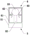
FIG. 2 is a schematic structural view of the self-locking head and the self-locking sleeve of the present invention;
fig. 3 is a schematic structural view after the folding of the present invention.
In the figure: the telescopic adjusting support comprises a base plate 1, a storage drawer 2, a folding steel frame mechanism 3, a support pillar 4, a self-locking head 5, a mounting plate 51, a support rod 52, a self-locking ball 53, a self-locking sleeve 6, an outer sleeve 61, a support spring 62, a self-locking plate 63, an upper support table 7 and a telescopic adjusting support pillar 8.
Detailed Description
The technical solutions in the embodiments of the present invention will be described clearly and completely with reference to the accompanying drawings in the embodiments of the present invention, and it is obvious that the described embodiments are only some embodiments of the present invention, not all embodiments. Based on the embodiments in the present invention, all other embodiments obtained by a person skilled in the art without creative work belong to the protection scope of the present invention.
In the description of the present invention, it is to be understood that the terms "upper", "lower", "front", "rear", "left", "right", "top", "bottom", "inner", "outer", and the like indicate orientations or positional relationships based on the orientations or positional relationships shown in the drawings, and are only for convenience of description and simplicity of description, and do not indicate or imply that the device or element being referred to must have a particular orientation, be constructed and operated in a particular orientation, and therefore, should not be construed as limiting the present invention.
Example (b):
referring to fig. 1-3, the present invention provides a technical solution: a foldable mechanical arm steel frame structure for construction engineering comprises a bottom plate 1, wherein a foldable steel frame mechanism 3 is arranged on the upper surface of the bottom plate 1, the foldable steel frame mechanism 3 comprises steel frame support arms, the end parts of the steel frame support arms are sequentially connected through a rotating shaft, two adjacent steel frame support arms are fixedly connected through a support pillar 4, an auto-lock head 5 and an auto-lock sleeve 6 are respectively arranged between visual side walls of the two adjacent steel frame support arms, the auto-lock head 5 corresponds to the auto-lock sleeve 6 in position, the auto-lock head 5 and the auto-lock sleeve 6 are positioned on one side, far away from the rotating shaft, of the steel frame support arms, the auto-lock head 5 comprises a mounting plate 51, a support rod 52 and an auto-lock ball 53, the support rod 52 is fixedly connected between the mounting plate 51 and the auto-lock ball 53, the auto-lock sleeve 6 comprises an outer sleeve 61, both sides of the inner part, the upper end of the steel frame support arm at the uppermost side is provided with an upper support table 7.
Further, a storage drawer 2 is arranged on the side wall of the bottom plate 1, and the depth of the storage drawer 2 is not less than the length of the support pillar 4.
Further, the even welding of the lower surface of going up supporting bench 7 has scalable regulation pillar 8, the bottom of scalable regulation pillar 8 and the steelframe support arm upper surface welding of the top.
Further, the self-locking plates 63 are arc-shaped, and the minimum distance between the self-locking plates 63 on both sides is smaller than the diameter value of the self-locking ball 53.
The working principle is as follows: when the folding steel frame mechanism is used, each steel frame support arm of the folding steel frame mechanism 3 is extended, the support strut 4 is connected between two adjacent steel frame support arms through a connecting pin or a bolt, so that the support is stable, the degree of adjustment of the telescopic adjusting strut 8 is adjusted, the upper support table 7 is in a horizontal state relative to the ground, and the mechanical arm can keep a normal working state after the mechanical arm is installed;
during the shrink, dismantle from folding steel frame mechanism 3's steel frame support arm with support post 4, later accomodate support post 4 and receive in drawer 2, the steel frame support arm shrink with folding steel frame mechanism 3, make from tapered end 5 correspond the card in from lock sleeve 6, from lock ball 53 inserts in outer sleeve 61, under supporting spring 62's elasticity supporting role, make the self-locking board 63 of both sides draw close, thereby with the elastic clamping of self-locking ball 53, make from tapered end 5 and from being difficult to the separation between the lock sleeve 6.
Having shown and described the basic principles and principal features of the invention and advantages thereof, it will be apparent to those skilled in the art that the invention is not limited to the details of the foregoing exemplary embodiments, but is capable of other specific forms without departing from the spirit or essential characteristics thereof; the present embodiments are therefore to be considered in all respects as illustrative and not restrictive, the scope of the invention being indicated by the appended claims rather than by the foregoing description, and all changes which come within the meaning and range of equivalency of the claims are therefore intended to be embraced therein, and any reference signs in the claims are not intended to be construed as limiting the claim concerned.
Although embodiments of the present invention have been shown and described, it will be appreciated by those skilled in the art that changes, modifications, substitutions and alterations can be made in these embodiments without departing from the principles and spirit of the invention, the scope of which is defined in the appended claims and their equivalents.
Claims (4)
1. The utility model provides a foldable mechanical arm steel frame construction for building engineering, includes bottom plate (1), its characterized in that: the upper surface of the bottom plate (1) is provided with a folding steel frame mechanism (3), the folding steel frame mechanism (3) comprises steel frame support arms, the end parts of the steel frame support arms are sequentially connected through a rotating shaft, two adjacent steel frame support arms are fixedly connected through a support pillar (4), a self-locking head (5) and a self-locking sleeve (6) are respectively arranged between the viewing side walls of the two adjacent steel frame support arms, the positions of the self-locking head (5) and the self-locking sleeve (6) are corresponding, the self-locking head (5) and the self-locking sleeve (6) are positioned on one side, far away from the rotating shaft, of the steel frame support arms, the self-locking head (5) comprises a mounting plate (51), a support rod (52) and a self-locking ball (53), the support rod (52) is fixedly connected between the mounting plate (51) and the self-locking ball (53), the self-locking sleeve (6) comprises, both sides supporting spring (62) one end that is close to mutually all is connected with from jam plate (63), the top the upper end of steelframe support arm is provided with supporting bench (7).
2. The foldable mechanical arm steel frame structure for construction engineering according to claim 1, wherein: the side wall of the bottom plate (1) is provided with a storage drawer (2), and the depth of the storage drawer (2) is not less than the length of the support pillar (4).
3. The foldable mechanical arm steel frame structure for construction engineering according to claim 1, wherein: go up the even welding of lower surface of supporting bench (7) has scalable regulation pillar (8), the bottom of scalable regulation pillar (8) and the steelframe support arm upper surface welding of the top.
4. The foldable mechanical arm steel frame structure for construction engineering according to claim 1, wherein: the self-locking plates (63) are arc-shaped, and the minimum distance between the self-locking plates (63) on two sides is smaller than the diameter value of the self-locking ball (53).
Priority Applications (1)
| Application Number | Priority Date | Filing Date | Title |
|---|---|---|---|
| CN202021678384.XU CN213226271U (en) | 2020-08-13 | 2020-08-13 | Foldable mechanical arm steel frame structure for building engineering |
Applications Claiming Priority (1)
| Application Number | Priority Date | Filing Date | Title |
|---|---|---|---|
| CN202021678384.XU CN213226271U (en) | 2020-08-13 | 2020-08-13 | Foldable mechanical arm steel frame structure for building engineering |
Publications (1)
| Publication Number | Publication Date |
|---|---|
| CN213226271U true CN213226271U (en) | 2021-05-18 |
Family
ID=75894571
Family Applications (1)
| Application Number | Title | Priority Date | Filing Date |
|---|---|---|---|
| CN202021678384.XU Active CN213226271U (en) | 2020-08-13 | 2020-08-13 | Foldable mechanical arm steel frame structure for building engineering |
Country Status (1)
| Country | Link |
|---|---|
| CN (1) | CN213226271U (en) |
-
2020
- 2020-08-13 CN CN202021678384.XU patent/CN213226271U/en active Active
Similar Documents
| Publication | Publication Date | Title |
|---|---|---|
| CN213226271U (en) | Foldable mechanical arm steel frame structure for building engineering | |
| CN115005598B (en) | Multifunctional art workbench | |
| CN215107682U (en) | Large-scale flexible sunshade canopy | |
| CN215445895U (en) | Adjustable atmospheric sampling device for environmental monitoring | |
| CN212462391U (en) | Electric power electrical cabinet with buffering function and easy connection | |
| CN211533470U (en) | Drawing panel for engineering cost | |
| CN112259025A (en) | Billboard with folding function and use method thereof | |
| CN220364348U (en) | Combined turnover machine for concrete member | |
| CN210457339U (en) | Auxiliary upright device of insulator core rod | |
| CN220711397U (en) | Adjustable folding photovoltaic support | |
| CN219270413U (en) | Design table with show function | |
| CN212105032U (en) | Equipment maintenance sliding platform in limited space | |
| CN210930394U (en) | Drawing fixing device for engineering cost | |
| CN213664201U (en) | Portable drawing is workstation for survey and drawing | |
| CN219994088U (en) | Connecting support of folding steamed vermicelli roll machine operation panel | |
| CN216854865U (en) | Operating room nursing tray | |
| CN218682763U (en) | Double-cross folding table | |
| CN213042626U (en) | Architectural design auxiliary assembly | |
| CN215820105U (en) | Working device for construction engineering cost | |
| CN215510947U (en) | Workstation is used in building engineering quality testing | |
| CN215817239U (en) | Portable transmission line overhauls uses work platform | |
| CN211388657U (en) | Production workbench | |
| CN214587717U (en) | Fixer for field construction site safety sign board | |
| CN220675575U (en) | Folding steel structure | |
| CN215490413U (en) | Solar panel with quick folding function |
Legal Events
| Date | Code | Title | Description |
|---|---|---|---|
| GR01 | Patent grant | ||
| GR01 | Patent grant |