High-efficient chemical industry effluent disposal system
Technical Field
The utility model relates to a chemical industry waste water treatment technical field, concretely relates to high-efficient chemical industry waste water treatment system.
Background
Chemical industry includes two main types of organic chemical industry and inorganic chemical industry, and the chemical products are various, and the composition is complicated, and discharged waste water is also various, and most have the hypertoxic and difficult purification, has certain accumulation effect in the organism, has obvious oxygen consumption nature in the water, has appeared the waste water treatment equipment for different kinds of chemical industry on the market, but current treatment facility majority does not have energy-conserving characteristics, and the treatment effect is also relatively poor.
SUMMERY OF THE UTILITY MODEL
The utility model aims at providing a high-efficient chemical industry effluent disposal system to prior art not enough, concrete scheme is as follows:
a high-efficiency chemical wastewater treatment system comprises a stirring box, wherein a rotating shaft is arranged in the stirring box, the rotating shaft is rotatably arranged in the stirring box through a bearing fixedly arranged on the stirring box, a spiral pushing blade is arranged on the rotating shaft, a hook tooth is arranged on a pushing surface of the spiral pushing blade, a liquid level meter is also arranged in the stirring box, and a driving motor for driving the rotating shaft to rotate is arranged outside the stirring box; the upper part of the end part of the stirring box is connected to a dosing chamber through a blanking pipe, one side of the dosing chamber is connected with a waste water pipe, a water flow sensor is arranged in the waste water pipe, the top of the dosing chamber is connected with a dosing device, an outlet is arranged below the tail part of the stirring box, and a sedimentation tank is connected below the outlet in a direct connection mode; an inclined tube filler is arranged inside the sedimentation tank, the bottom of the sedimentation tank is a conical surface, a mud level meter is arranged on the conical surface, a mud discharge port is arranged at the lowest part of the conical surface, a second electromagnetic valve is arranged in the mud discharge port, a sludge tank is arranged below the mud discharge port correspondingly, an overflow port is arranged on the side surface of the sedimentation tank, and the overflow port is in direct connection with a clean water tank; the liquid level meter, the driving motor, the water flow sensor, the second electromagnetic valve and the mud level meter are electrically connected to a controller arranged on the stirring box.
Based on the above, charge device includes the medical kit, the medical kit top is equipped with the charge door, is equipped with the bull stick in the medical kit, be equipped with spiral stirring leaf and many puddlers on the bull stick, be equipped with the otter board on the puddler, the top of medical kit is equipped with drive bull stick pivoted agitator motor, the below of medical kit be equipped with many with add the pencil that adds of medicine room intercommunication, all be equipped with first battery valve in the pencil, the equal electric connection of agitator motor, first solenoid valve to the controller.
Based on the above, a first baffle and a second baffle are arranged in the clean water tank, an aeration zone is arranged between the first baffle and the second baffle, and an aeration device is arranged below the aeration zone.
Based on the above, aeration equipment is including setting up the micropore aeration board of clean water basin bottom, the below of micropore aeration board is equipped with the aeration cover, the aeration cover is connected to the gas vent of gas transmission pump through the blast pipe, the air inlet of gas transmission pump is connected to ozone generating device through the intake-tube, be equipped with the check gas valve in the blast pipe.
Based on the above, a plurality of mixed flow blade groups are arranged in the blanking pipe, each mixed flow blade group comprises a plurality of guide vanes, a guide opening is formed between every two adjacent guide vanes, and the directions of the guide openings of the adjacent mixed flow blade groups are opposite.
The utility model discloses relative prior art has substantive characteristics and progress, specifically speaking, the utility model has the following advantages:
1. the utility model discloses in, through set up the rivers sensor in the waste pipe, the below of medical kit sets up a plurality of medicine pipes that extend to with the medicine room, sets up first solenoid valve in the medicine pipe, and this structural design can be according to the quantity of the first solenoid valve that the size control of rivers was opened, and then guarantees that the liquid medicine that adds can enough handle waste water in the past waste water, can avoid the waste of liquid medicine again.
2. In the utility model, a plurality of mixed flow blade groups are arranged in the blanking pipe, each mixed flow blade group comprises a plurality of guide vanes, a guide opening is formed between every two adjacent guide vanes, the directions of the guide openings of the adjacent mixed flow blade groups are opposite, and the structural design can preliminarily mix the waste water after adding the chemicals; the tooth is hooked on the pushing surface of the spiral pushing blade, so that the wastewater can be ensured to be further uniformly mixed with the liquid medicine, and the wastewater treatment effect is further ensured.
3. The utility model discloses in, through the aeration zone that sets up by first baffle, second baffle formation in the clean water basin, set up aeration equipment below the aeration zone, can ensure that waste water purifies thoroughly to the further oxidation treatment of waste water after the purification treatment.
Drawings
Fig. 1 is a schematic view of the overall structure of the present invention.
Fig. 2 is a schematic structural view of the middle drug adding device of the utility model.
Fig. 3 is a schematic structural view of the middle aeration device of the utility model.
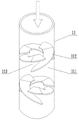
Fig. 4 is a schematic structural view of the blanking pipe of the present invention.
In the figure: 1. a stirring box; 2. a rotating shaft; 3. spirally pushing the leaves; 4. a bearing; 5. a drive motor; 6. a liquid level meter; 7. a dosing chamber; 8. a waste pipe; 9. a water flow sensor; 10. a dosing device; 101. a medicine chest; 102. a rotating rod; 103. a spiral stirring blade; 104. a stirring rod; 105. a screen plate; 106. a stirring motor; 107. a medicine feeding pipe; 108. a first solenoid valve; 109. a feed inlet; 11. a discharging pipe; 111. a mixed flow vane set; 112. a guide vane; 113. a flow guide port; 12. a sedimentation tank; 13. a conical surface; 14. a mud level meter; 15. a sludge discharge port; 16. a second solenoid valve; 17. a sludge tank; 18. an overflow port; 19. a pool; 20. a first baffle plate; 21. a second baffle; 22. an aeration zone; 23. an aeration device; 231. an ozone generating device; 232. an air delivery pump; 233. an exhaust pipe; 234. an aeration cover; 235. a microporous aeration plate; 236. a one-way gas valve; 28. filling the inclined tube; 29. and a controller.
Detailed Description
The technical solution of the present invention will be described in further detail through the following embodiments.
Examples
As shown in fig. 1-4, the utility model provides a high-efficient chemical industry effluent disposal system, including agitator tank 1, be equipped with pivot 2 in the agitator tank 1, pivot 2 rotates through the bearing 4 that sets firmly on agitator tank 1 and installs in agitator tank 1, is equipped with spiral propelling movement leaf 3 in the pivot 2, and the propelling movement face equipartition of spiral propelling movement leaf 3 is equipped with the mixed effect of colluding the tooth in order to improve agitator tank 1, still is equipped with level gauge 6 in the agitator tank 1, is equipped with the drive outside agitator tank 1 pivot 2 pivoted driving motor 5.
The end part top of the stirring box 1 is connected to a dosing chamber 7 through a discharging pipe 11, one side of the dosing chamber 7 is connected with a waste water pipe 8, a water flow sensor 9 is arranged in the waste water pipe 8, the top of the dosing chamber 7 is connected with a dosing device 10, an outlet is arranged below the tail part of the stirring box 1, and a sedimentation tank 12 is connected below the outlet in a sequential manner.
In order to ensure the sedimentation efficiency of the sedimentation tank 12, the inner part of the sedimentation tank 12 is provided with an inclined tube filler 28, the bottom of the sedimentation tank 12 is a conical surface 13, the conical surface 13 is provided with a mud level meter 14, the lowest part of the conical surface 13 is provided with a mud discharging port 15, the mud discharging port 15 is internally provided with a second electromagnetic valve 16, the lower part corresponding to the mud discharging port 15 is provided with a sludge tank 17, the side surface of the sedimentation tank 12 is provided with an overflow port 18, and the overflow port 18 is sequentially connected with a clean water tank 19.
The liquid level meter 6, the driving motor 5, the water flow sensor 9, the second electromagnetic valve 16, the mud level meter 14 and the water pump 24 are all electrically connected to a controller 29 arranged on the stirring tank 1.
It should be noted that, in order to ensure that the liquid medicine and the wastewater are uniformly mixed, a plurality of mixed flow blade sets 111 are arranged in the feeding pipe 11, each mixed flow blade set 111 includes a plurality of guide vanes 112, a guide opening 113 is formed between adjacent guide vanes 112, and the directions of the guide openings 113 of the adjacent mixed flow blade sets 111 are opposite.
Medicine device 10 includes medical kit 101, and medical kit 101 is used for the splendid attire to carry out liquid medicine, the flocculating agent that handles waste water, and medical kit 101 top is equipped with charge door 109, is equipped with bull stick 102 in the medical kit 101, be equipped with spiral stirring leaf 103 and many puddlers 104 on the bull stick 102, be equipped with otter board 105 on the puddler 104, the top of medical kit 101 is equipped with drive bull stick 102 pivoted agitator motor 106, the below of medical kit 101 be equipped with many with add the pencil 107 that adds of medicine room 7 intercommunication, all be equipped with first battery valve in adding the pencil 107, agitator motor 106, the equal electric connection of first solenoid valve 108 to controller 29.
Considering that the wastewater after the chemical adding and precipitating treatment may also contain some toxic substances, in order to perform the purification treatment, a first baffle 20 and a second baffle 21 are particularly arranged in the clean water tank 19, an aeration zone 22 is arranged between the first baffle 20 and the second baffle 21, and an aeration device 23 is arranged below the aeration zone 22.
The aeration device 23 comprises a microporous aeration plate 235 arranged at the bottom of the clean water tank 19, an aeration cover 234 is arranged below the microporous aeration plate 235, the aeration cover 234 is connected to an exhaust port of an air delivery pump 232 through an exhaust pipe 233, an air inlet of the air delivery pump 232 is connected to an ozone generating device 231 through an air inlet pipe, and a one-way air valve 236 is arranged in the exhaust pipe 233.
The utility model discloses specific theory of operation as follows: the flow of the wastewater in the wastewater pipe 8 is monitored by the water flow sensor 9, the controller 29 opens the first electromagnetic valves 108 with different quantities according to the water flow to add the medicine into the wastewater, the liquid medicine and the wastewater flow through the discharging pipe 11 and then are subjected to preliminary static mixing through the mixed flow blade group 111, then the wastewater enters the stirring box 1, the controller 29 adjusts the rotating speed of the driving motor 5 according to the liquid level in the stirring box 1 measured by the liquid level meter 6, the wastewater is stirred and pushed to the sedimentation tank 12 under the action of the spiral pushing blade 3 and the hook teeth, the sludge sinks under the action of the inclined pipe filler 28, the wastewater after sedimentation and purification is discharged into the clean water tank 19 through the overflow port 18, and the wastewater is subjected to ozone deep oxidation treatment again under the action of the aeration device 23.
The sludge level meter 14 monitors the position of the sludge in real time, and when the sludge is deposited too much, the second electromagnetic valve is opened by the controller 29 and the sludge is discharged into the sludge tank 17.
Finally, it should be noted that: the above embodiments are only used to illustrate the technical solution of the present invention and not to limit it; although the present invention has been described in detail with reference to preferred embodiments, it should be understood by those skilled in the art that: the invention can be modified or equivalent substituted for some technical features; without departing from the spirit of the present invention, it should be understood that the scope of the claims is intended to cover all such modifications and variations.