CN213152559U - Server placer for optical fiber data transmission - Google Patents
Server placer for optical fiber data transmission Download PDFInfo
- Publication number
- CN213152559U CN213152559U CN202021954201.2U CN202021954201U CN213152559U CN 213152559 U CN213152559 U CN 213152559U CN 202021954201 U CN202021954201 U CN 202021954201U CN 213152559 U CN213152559 U CN 213152559U
- Authority
- CN
- China
- Prior art keywords
- server
- cabinet body
- electric cabinet
- wire
- regulator cubicle
- Prior art date
- Legal status (The legal status is an assumption and is not a legal conclusion. Google has not performed a legal analysis and makes no representation as to the accuracy of the status listed.)
- Expired - Fee Related
Links
Images


Landscapes
- Cooling Or The Like Of Electrical Apparatus (AREA)
Abstract
The utility model relates to a server regulator cubicle technical field just discloses a server placer for transmission of optical fiber data, including the regulator cubicle cabinet body, the bottom fixed mounting of the regulator cubicle cabinet body has the regulator cubicle base, the equal fixed mounting in the left and right sides of regulator cubicle base has dustproof shutter, the inside of dustproof shutter is pegged graft and is had the dust screen, the inside top fixed mounting of regulator cubicle base has radiator fan, and the regulator cubicle base back has seted up the wire rod export, the front of the regulator cubicle cabinet body is rotated with the inboard of front side cabinet door through preceding cabinet door hinge and is connected, and the inside fixed mounting of the regulator cubicle cabinet body has. The utility model discloses an at regulator cubicle cabinet body back mounted rear side cabinet door, can come to carry out the wiring installation to the server from the back, can use the cable tie with the wire rod of installing to fix on the wire rod fixing base moreover to be convenient for installation and the follow-up maintenance of server wire rod.
Description
Technical Field
The utility model relates to a server regulator cubicle technical field especially relates to a server placer for optical fiber data transmission.
Background
The server placing device generally refers to a cabinet body for placing various servers, and the server electrical cabinet plays a role in protecting the servers on the internal storage rack and generally has the functions of dust prevention, heat dissipation, electromagnetic radiation isolation and the like.
A prior patent (publication No. CN210840415U) discloses a server placement apparatus including: the server comprises a shell, wherein at least one pair of supporting frames for supporting the server is arranged at two ends of the inner wall of the shell, a vibration damping structure is arranged on one side, close to the server, of each supporting frame, and each vibration damping structure comprises a groove arranged on each supporting frame, an elastic piece arranged in each groove and a supporting plate arranged at one end, far away from the corresponding groove, of each elastic piece; when the elastic piece is in a compressed state due to the gravity of the server, one side of the supporting plate, which is far away from the elastic piece, is higher than one side of the supporting frame, which is close to the supporting plate. Under the action of gravity of the server, the supporting plate compresses the elastic part, the surface of the supporting plate is higher than that of the supporting frame, so that the server is not in direct contact with the supporting frame, energy input from the outside is attenuated through the elastic part, and the supporting frame is lightened or resonance of the supporting frame is prevented. The inventor finds that the following problems in the prior art are not solved well in the process of realizing the scheme: 1. the device does not have a wire arrangement device for connecting wires at the back of the server, and is inconvenient for wire installation and subsequent maintenance; 2. the device does not have a heat dissipation device for the server, and can cause heat accumulation in the electric cabinet, so that a server main body is damaged.
SUMMERY OF THE UTILITY MODEL
The purpose of the utility model is to solve the shortcoming that exists among the prior art, if: the device does not have a wire arranging device for connecting wires at the back of the server, is inconvenient for wire installation and subsequent maintenance, does not have a heat radiating device for the server, and can certainly cause heat accumulation in an electric cabinet so as to damage the server main body.
In order to achieve the above purpose, the utility model adopts the following technical scheme: a server placing device for optical fiber data transmission comprises an electrical cabinet body, wherein an electrical cabinet base is fixedly arranged at the bottom of the electrical cabinet body, the left side and the right side of the electrical cabinet base are both fixedly provided with dustproof shutters, the interior of each dustproof shutter is spliced with a dustproof net, the top of the interior of the electrical cabinet base is fixedly provided with a radiating fan, and the back of the electric cabinet base is provided with a wire outlet, the front of the electric cabinet body is rotationally connected with the inner side of the front cabinet door through a front cabinet door hinge, and the inside of the cabinet body of the electric cabinet is fixedly provided with a server placing frame, the inside of the cabinet body of the electric cabinet is fixedly provided with a wire backboard, the inside of the wire backboard is provided with a wire through hole, and the back of the wire back plate is fixedly provided with a wire fixing seat, the top of the electrical cabinet base is provided with a wire passage, the back of the cabinet body of the electric cabinet is rotatably connected with the inner side of the rear side cabinet door through a rear cabinet door hinge.
Preferably, the dust screen forms a sliding structure in the dust-proof shutter, and the dust screen is a detachable structure for the dust-proof shutter.
Preferably, the front side cabinet door forms a rotating structure on the cabinet body of the electrical cabinet through a hinge of the front cabinet door.
Preferably, seven layers of server racks are arranged inside the cabinet body of the electrical cabinet, and the seven layers of server racks are distributed at equal intervals.
Preferably, seven layers of wire rod through holes are formed in the wire rod back plate, and the inner walls of the wire rod through holes are of circular arc structures.
Preferably, the interior of the cabinet body of the electrical cabinet forms a communication structure with the exterior through the wire passage and the wire outlet.
Compared with the prior art, the beneficial effects of the utility model are that:
(1) the utility model discloses an at regulator cubicle cabinet body back mounted rear side cabinet door, can come to carry out the wiring installation to the server from the back, can use the cable tie with the wire rod of installing to fix on the wire rod fixing base moreover to be convenient for installation and the follow-up maintenance of server wire rod.
(2) The utility model discloses an installed dust screen and radiator fan bottom the regulator cubicle, can carry the internal portion of regulator cubicle cabinet with outside cold air to reduce the temperature of the internal portion of regulator cubicle cabinet, the detachable design of dust screen is convenient for also daily maintenance and cleanness.
Drawings
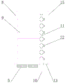
FIG. 1 is a front view of the structure of the present invention;
FIG. 2 is a side sectional view of the structure of the present invention;
fig. 3 is a back view of the structure of the present invention.
In the figure: 1. an electrical cabinet body; 2. an electrical cabinet base; 3. a dustproof shutter; 4. a dust screen; 5. a heat radiation fan; 6. a wire outlet; 7. a front cabinet door hinge; 8. a front side cabinet door; 9. placing a server rack; 10. a wire back plate; 11. a wire through hole; 12. a wire fixing seat; 13. a wire passage; 14. a rear cabinet door hinge; 15. a rear cabinet door.
Detailed Description
The technical solutions in the embodiments of the present invention will be described clearly and completely with reference to the accompanying drawings in the embodiments of the present invention, and it is obvious that the described embodiments are only some embodiments of the present invention, not all embodiments.
In the description of the present invention, it is to be understood that the terms "upper", "lower", "front", "rear", "left", "right", "top", "bottom", "inner", "outer", and the like indicate orientations or positional relationships based on the orientations or positional relationships shown in the drawings, and are only for convenience of description and simplicity of description, and do not indicate or imply that the device or element being referred to must have a particular orientation, be constructed and operated in a particular orientation, and therefore, should not be construed as limiting the present invention.
Referring to fig. 1-3, a server placement device for optical fiber data transmission comprises an electrical cabinet body 1, an electrical cabinet base 2 is fixedly installed at the bottom of the electrical cabinet body 1, dustproof shutters 3 are fixedly installed at the left side and the right side of the electrical cabinet base 2, dustproof nets 4 are inserted into the dustproof shutters 3, the dustproof nets 4 form a sliding structure in the dustproof shutters 3, the dustproof nets 4 are detachable structures relative to the dustproof shutters 3 and can facilitate daily maintenance, cleaning and cleaning, a cooling fan 5 is fixedly installed at the top inside the electrical cabinet base 2, a wire outlet 6 is formed in the back side of the electrical cabinet base 2, the front side of the electrical cabinet body 1 is rotatably connected with the inner side of a front cabinet door 8 through a front cabinet door hinge 7, a server placement frame 9 is fixedly installed inside the electrical cabinet body 1, and seven layers of server placement frames 9 are formed inside the electrical cabinet body, the seven layers of server racks 9 are distributed at equal intervals, so that the distances among the servers are the same, the attractiveness and the balance of heat dissipation inside the electric cabinet body 1 are ensured, the front side cabinet door 8 forms a rotating structure on the electric cabinet body 1 through a front cabinet door hinge 7 and can be rotated to open and close the front side cabinet door 8, a wire backboard 10 is fixedly installed inside the electric cabinet body 1, a wire through hole 11 is formed inside the wire backboard 10, the seven layers of wire through holes 11 are formed inside the wire backboard 10, the inner walls of the wire through holes 11 are of circular arc structures and can be prevented from scratching a wire when the wire passes through the wire through hole 11, a wire fixing seat 12 is fixedly installed on the back side of the wire backboard 10, a wire channel 13 is formed at the top of the electric cabinet base 2, and a communicating structure is formed between the inside of the electric cabinet body, the server wires can be connected with the outside through the wire passage 13 and the wire outlet 6, and the back of the electric cabinet body 1 is rotatably connected with the inner side of the rear side cabinet door 15 through a rear cabinet door hinge 14.
The working principle is as follows: at first, open front cabinet door 8 and rear cabinet door 15, place the server host computer on server rack 9, then insert the server wire rod from wire rod export 6, and get into the regulator cubicle cabinet body 1 inside through wire rod passageway 13, then be connected with the server host computer from each wire rod through-hole 11 respectively, use the area of bundling to fix the wire rod on wire rod fixing base 12 after the regulator cubicle cabinet body 1 inside wiring is accomplished, then close front cabinet door 8 and rear cabinet door 15, radiator fan 5 starts to pass through the inside of dust screen 4 suction regulator cubicle cabinet body 1 with outside cold air when the server host computer moves, regular maintenance only need clear up dust screen 4 afterwards can, so above be exactly this server placement device for optical fiber data transmission's concrete theory of operation.
The above, only be the concrete implementation of the preferred embodiment of the present invention, but the protection scope of the present invention is not limited thereto, and any person skilled in the art is in the technical scope of the present invention, according to the technical solution of the present invention and the utility model, the concept of which is equivalent to replace or change, should be covered within the protection scope of the present invention.
It is noted that, herein, relational terms such as first and second, and the like may be used solely to distinguish one entity or action from another entity or action without necessarily requiring or implying any actual such relationship or order between such entities or actions. Also, the terms "comprises," "comprising," or any other variation thereof, are intended to cover a non-exclusive inclusion, such that a process, method, article, or apparatus that comprises a list of elements does not include only those elements but may include other elements not expressly listed or inherent to such process, method, article, or apparatus.
Claims (6)
1. The utility model provides a server placer for optical fiber data transmission, includes regulator cubicle cabinet body (1), its characterized in that: the electric cabinet is characterized in that an electric cabinet base (2) is fixedly installed at the bottom of the electric cabinet body (1), dustproof shutters (3) are fixedly installed on the left side and the right side of the electric cabinet base (2), dustproof nets (4) are inserted into the dustproof shutters (3), a heat radiation fan (5) is fixedly installed at the top of the inner part of the electric cabinet base (2), a wire outlet (6) is formed in the back of the electric cabinet base (2), the front of the electric cabinet body (1) is rotatably connected with the inner side of a front side cabinet door (8) through a front cabinet door hinge (7), a server placing frame (9) is fixedly installed in the electric cabinet body (1), a wire back plate (10) is fixedly installed in the electric cabinet body (1), a wire through hole (11) is formed in the wire back plate (10), and a wire fixing seat (12) is fixedly installed on the back, the wire rod channel (13) is formed in the top of the electric cabinet base (2), and the back face of the electric cabinet body (1) is rotatably connected with the inner side of a rear cabinet door (15) through a rear cabinet door hinge (14).
2. The server placement device for optical fiber data transmission according to claim 1, wherein: the dustproof net (4) forms a sliding structure in the dustproof shutter (3), and the dustproof net (4) is of a detachable structure for the dustproof shutter (3).
3. The server placement device for optical fiber data transmission according to claim 1, wherein: the front side cabinet door (8) forms a rotating structure on the electric cabinet body (1) through a front cabinet door hinge (7).
4. The server placement device for optical fiber data transmission according to claim 1, wherein: seven layers of server placing frames (9) are arranged inside the electric cabinet body (1), and the seven layers of server placing frames (9) are distributed at equal intervals.
5. The server placement device for optical fiber data transmission according to claim 1, wherein: seven layers of wire rod through holes (11) are formed in the wire rod back plate (10), and the inner walls of the wire rod through holes (11) are of circular arc structures.
6. The server placement device for optical fiber data transmission according to claim 1, wherein: the interior of the electric cabinet body (1) forms a communicating structure with the exterior through a wire channel (13) and a wire outlet (6).
Priority Applications (1)
| Application Number | Priority Date | Filing Date | Title |
|---|---|---|---|
| CN202021954201.2U CN213152559U (en) | 2020-09-09 | 2020-09-09 | Server placer for optical fiber data transmission |
Applications Claiming Priority (1)
| Application Number | Priority Date | Filing Date | Title |
|---|---|---|---|
| CN202021954201.2U CN213152559U (en) | 2020-09-09 | 2020-09-09 | Server placer for optical fiber data transmission |
Publications (1)
| Publication Number | Publication Date |
|---|---|
| CN213152559U true CN213152559U (en) | 2021-05-07 |
Family
ID=75711521
Family Applications (1)
| Application Number | Title | Priority Date | Filing Date |
|---|---|---|---|
| CN202021954201.2U Expired - Fee Related CN213152559U (en) | 2020-09-09 | 2020-09-09 | Server placer for optical fiber data transmission |
Country Status (1)
| Country | Link |
|---|---|
| CN (1) | CN213152559U (en) |
Cited By (1)
| Publication number | Priority date | Publication date | Assignee | Title |
|---|---|---|---|---|
| CN114153296A (en) * | 2021-12-07 | 2022-03-08 | 江苏京磁信息技术有限公司 | Server state monitoring and adjusting device |
-
2020
- 2020-09-09 CN CN202021954201.2U patent/CN213152559U/en not_active Expired - Fee Related
Cited By (1)
| Publication number | Priority date | Publication date | Assignee | Title |
|---|---|---|---|---|
| CN114153296A (en) * | 2021-12-07 | 2022-03-08 | 江苏京磁信息技术有限公司 | Server state monitoring and adjusting device |
Similar Documents
| Publication | Publication Date | Title |
|---|---|---|
| EP0741958B1 (en) | Housing with heat-liberating equipment | |
| US7255640B2 (en) | Cable and air management adapter system for enclosures housing electronic equipment | |
| US6788535B2 (en) | Outdoor electronic equipment cabinet | |
| WO2011090874A1 (en) | Adjustable blanking panel | |
| US20060158866A1 (en) | Electronic system cabinet having a lower panel with an opening to receive cables | |
| CN213152559U (en) | Server placer for optical fiber data transmission | |
| US20060269207A1 (en) | Information technology communications cabinet for electrical substation communications | |
| CN111050227A (en) | Intelligent cloud cabinet and use method | |
| CN212163863U (en) | Multicomputer cabinet convenient to place respectively | |
| CN210986627U (en) | Anti-interference communication cabinet | |
| CN111918517A (en) | Stack type installation structure of server for computer network architecture | |
| KR102200539B1 (en) | the improved server rack and the server rack arrangement structure using the same | |
| CN107911757A (en) | A kind of communication box with antidetonation heat sinking function | |
| CN216313323U (en) | Switch chassis for big data management | |
| US7099550B1 (en) | Angular optical component retention and removal system | |
| CN218042088U (en) | Network rack with prevent static function | |
| CN220985995U (en) | Adjustable multifunctional server cabinet | |
| CN212463805U (en) | Computer network equipment cabinet | |
| CN221043112U (en) | Switch shell structure | |
| CN217088325U (en) | Big data server rack | |
| CN212786218U (en) | Building security protection control rack | |
| CN212786156U (en) | Thing networking gateway protection device | |
| CN220173613U (en) | Flexible engineering service mainframe cabinet | |
| CN220732928U (en) | Exchanger for information data transmission | |
| CN207427660U (en) | A kind of portable computer network cabinet |
Legal Events
| Date | Code | Title | Description |
|---|---|---|---|
| GR01 | Patent grant | ||
| GR01 | Patent grant | ||
| CF01 | Termination of patent right due to non-payment of annual fee | ||
| CF01 | Termination of patent right due to non-payment of annual fee |
Granted publication date: 20210507 Termination date: 20210909 |