CN212989948U - Detection tool for electric actuator control panel - Google Patents
Detection tool for electric actuator control panel Download PDFInfo
- Publication number
- CN212989948U CN212989948U CN202022276262.4U CN202022276262U CN212989948U CN 212989948 U CN212989948 U CN 212989948U CN 202022276262 U CN202022276262 U CN 202022276262U CN 212989948 U CN212989948 U CN 212989948U
- Authority
- CN
- China
- Prior art keywords
- plate
- detection
- groove
- control panel
- electric actuator
- Prior art date
- Legal status (The legal status is an assumption and is not a legal conclusion. Google has not performed a legal analysis and makes no representation as to the accuracy of the status listed.)
- Active
Links
Images


Landscapes
- Machine Tool Sensing Apparatuses (AREA)
Abstract
The utility model provides a detection tool for an electric actuator control panel, which comprises an operation table, wherein the top end of the operation table is provided with a detection groove, the front surface and the back surface of the operation table are provided with pulley grooves, pulleys are arranged inside the two pulley grooves, a support rod is sleeved outside the two pulleys, the top end of the support rod is in threaded connection with a rotating rod, the bottom end of the rotating rod is in rotational connection with a detection plate, the two sides of the detection plate are mutually matched with the two sides inside the detection groove, one side of the operation table is in threaded connection with a positioning lead screw, one end of the positioning lead screw is in rotational connection with a clamping block, the other side of the operation table is fixedly provided with a fixed plate, one side of the fixed plate is provided with a storage groove, the utility model utilizes the design of the storage groove, the detection plate can be arranged inside the storage groove when the, the entry of outside dust has been effectually avoided, has guaranteed the cleanliness of pick-up plate surface test element.
Description
Technical Field
The utility model relates to an electric actuator's technical field, concretely relates to detection frock that electric actuator control panel was used.
Background
The electric actuator is a driving device capable of providing linear or rotary motion, and utilizes some kind of driving energy source and works under the action of some kind of control signal, and its actuating mechanism uses liquid, gas, electric power or other energy source and utilizes motor, cylinder or other device to convert it into driving action, and the control signal produced by electric actuator when it is worked is all sent out by control board, so that the detection of control board is critical.
The detection tool for the control panel of the existing electric actuator mostly adopts the detection plate to detect the control panel, but the detection plate is often exposed outside under the condition of nonuse, and then dust is easily accumulated on the surface of the detection plate, so that the accuracy of a detection result is influenced, and the normal operation of the electric actuator is influenced.
SUMMERY OF THE UTILITY MODEL
The utility model mainly provides a detection frock that electric actuator control panel was used for solve the technical problem who proposes among the above-mentioned background art.
The utility model provides a technical scheme that above-mentioned technical problem adopted does:
the utility model provides a detection frock that electric actuator control panel was used, includes the operation panel, the top of operation panel has been seted up and has been examined test groove, the pulley groove has all been seted up, two at the front and the back of operation panel the pulley is all installed, two to the inside of pulley groove the bracing piece has been cup jointed to the outside of pulley, the bracing piece is the U-shaped, the top threaded connection of bracing piece has the bull stick, the bottom of bull stick is rotated and is connected with the pick-up plate, the both sides of pick-up plate mutually support with the both sides of examining test inslot portion, one side threaded connection of operation panel has the location lead screw, the one end of location lead screw is rotated and is connected with the grip block, the opposite side fixed mounting of operation panel has the fixed plate, one side of fixed plate.
The fixed plate is characterized in that sliding grooves are formed in the two sides of the front face of the fixed plate, two sliding blocks are connected to the inner portions of the sliding grooves in a sliding mode, one ends of the two sliding blocks are fixedly connected with upper sliding plates, and the other two ends of the sliding blocks are fixedly provided with lower sliding plates.
Arc holes are formed in the bottom end of the upper sliding plate and the top end of the lower sliding plate, the arc holes correspond to each other, and the arc holes are matched with the rotating rod.
One side sliding connection at slide down top has the movable block, the one end of movable block rotates and is connected with the connecting plate, one side fixedly connected with joint piece at connecting plate top.
A clamping groove is formed in one side of the bottom end of the upper sliding plate, the clamping groove is T-shaped, and the clamping groove is matched with the clamping block.
One side of grip block is fixed to be glued and is had the crashproof pad, the bottom of grip block and the bottom sliding connection who detects inslot portion.
Compared with the prior art, the beneficial effects of the utility model are that: one of which, the utility model discloses the design that utilizes and store the groove can be deposited the pick-up plate in the inside that stores the groove under the condition that does not use the detection frock, and the use of cooperation top slide and lower slide seals storing the groove, and the effectual entering of avoiding outside dust guarantees pick-up plate surface detection element's cleanliness, and then makes the testing result more accurate, the indirect normal operating that has ensured electric actuator.
Two, the utility model discloses the design that utilizes rotatable bracing piece can drive the pick-up plate and remove the optional position of operation panel top, and then can detect the control panel of different specifications, need not to change the detection frock of different specifications, the effect of cooperation grip block can be with the stable inside of fixing in the detection groove of control panel, contact well between pick-up plate and the control panel when guaranteeing to detect, avoid contact failure to lead to the unsafe phenomenon of testing result to take place, the bracing piece rotates simultaneously and can drive the pick-up plate and store the groove and be parallel to each other, deposit under the condition of not dismantling the pick-up plate, it is very convenient to operate, has fine practicality.
The present invention will be explained in detail with reference to the drawings and specific embodiments.
Drawings
FIG. 1 is a schematic view of the overall structure of the present invention;
FIG. 2 is a schematic view of the internal structure of the detection tank of the present invention;
FIG. 3 is a schematic view of the explosion structure on one side of the fixing plate of the present invention;
fig. 4 is an enlarged schematic structural view of a portion a in fig. 3 according to the present invention.
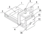
In the figure: 1. an operation table; 2. a detection tank; 3. a pulley groove; 4. a pulley; 5. a support bar; 6. a rotating rod; 7. detecting a plate; 8. positioning a screw rod; 9. a clamping block; 10. a fixing plate; 11. a storage tank; 12. an upper slide plate; 13. a lower slide plate; 14. a slider; 15. a chute; 16. an arc-shaped hole; 17. a movable block; 18. a connecting plate; 19. a clamping block; 20. a clamping groove.
Detailed Description
In order to facilitate understanding of the present invention, the present invention will be described more fully with reference to the accompanying drawings, in which several embodiments of the present invention are shown, but the present invention can be implemented in different forms, and is not limited to the embodiments described in the text, but rather, these embodiments are provided to make the disclosure of the present invention more thorough and comprehensive.
It will be understood that when an element is referred to as being "secured to" another element, it can be directly on the other element or intervening elements may be present, and when an element is referred to as being "connected" to another element, it can be directly connected to the other element or intervening elements may also be present, as the terms "vertical", "horizontal", "left", "right" and the like are used herein for descriptive purposes only.
Unless defined otherwise, all technical and scientific terms used herein have the same meaning as commonly understood by one of ordinary skill in the art to which this invention belongs, and the use of the term knowledge in the specification of the present invention is for the purpose of describing particular embodiments and is not intended to limit the present invention, and the term "and/or" as used herein includes any and all combinations of one or more of the associated listed items.
Please refer to fig. 1-4 with emphasis, a detection tool for a control panel of an electric actuator, comprising an operation table 1, a detection groove 2 is disposed at the top end of the operation table 1, pulley grooves 3 are disposed at the front and back of the operation table 1, pulleys 4 are disposed inside the two pulley grooves 3, a support rod 5 is sleeved outside the two pulleys 4, the support rod 5 is U-shaped, a rotating rod 6 is connected to the top end of the support rod 5 through a screw thread, a detection plate 7 is rotatably connected to the bottom end of the rotating rod 6, two sides of the detection plate 7 are matched with two sides of the detection groove 2, a positioning screw 8 is connected to one side of the operation table 1 through a screw thread, one end of the positioning screw 8 is rotatably connected with a clamping block 9, an anti-collision pad is fixedly bonded to one side of the clamping block 9, the bottom end of the clamping block 9 is slidably connected to the bottom end of the, a storage groove 11 is formed in one side of the fixed plate 10, and the storage groove 11 is matched with the detection plate 7.
The utility model discloses a concrete operation as follows: during the use, the operator at first upwards stimulates connecting plate 18, and connecting plate 18 drives joint piece 19 rebound, then outwards stimulates connecting plate 18, and connecting plate 18 will drive joint piece 19 break away from with the joint of joint groove 20, and lower slide 13 drives slider 14 under the effect of gravity and slides to the bottom of spout 15, then upwards drags upper slide 12 to beat slider 14 and slide to the top of spout 15, and then opens and store groove 11.
After the storage groove 11 is opened, the pulling rotating rod 6 drives the supporting rod 5 to move, the supporting rod 5 drives the pulley 4 to slide along the inside of the pulley groove 3, then the rotating rod 6 drives the detection plate 7 to be separated from the inside of the storage groove 11, the supporting rod 5 rotates at the moment, the supporting rod 5 drives the pulley 4 to rotate in the inside of the pulley groove 3, the top end of the supporting rod 5 is parallel to the detection groove 2, the rotating rod 6 drives the detection plate 7 to move towards the direction inside the detection groove 2 at the moment, the detection plate 7 stops after being contacted with a control plate, finally, the rotary positioning screw rod 8 drives the clamping block 9 to fix the control plate in the inside of the detection groove 2, and therefore detection work of the control plate is achieved.
Otherwise, after the detection is finished, the supporting rod 5 is pulled to move to one end of the pulley groove 3, then the rotating supporting rod 5 drives the detection plate 7 to be parallel to the fixed plate 10, finally the supporting rod 5 is pushed to drive the detection plate 7 to enter the inside of the storage groove 11, then the upper sliding plate 12 and the lower sliding plate 13 are respectively slid to be attached to each other, and then the clamping block 19 is pressed to the inside of the clamping groove 20, so that the storage step of the detection plate 7 is finished.
The present invention has been described above with reference to the accompanying drawings, and it is obvious that the present invention is not limited by the above-mentioned manner, if the method and the technical solution of the present invention are adopted, the present invention can be directly applied to other occasions without substantial improvement, and the present invention is within the protection scope of the present invention.
Claims (6)
1. The detection tool for the control panel of the electric actuator comprises an operation table (1) and is characterized in that a detection groove (2) is formed in the top end of the operation table (1), pulley grooves (3) are formed in the front face and the back face of the operation table (1), pulleys (4) are mounted inside the two pulley grooves (3), supporting rods (5) are sleeved outside the pulleys (4), the supporting rods (5) are U-shaped, a rotating rod (6) is connected to the top end of each supporting rod (5) in a threaded mode, a detection plate (7) is connected to the bottom end of each rotating rod (6) in a rotating mode, two sides of the detection plate (7) are matched with two sides of the interior of the detection groove (2), a positioning screw rod (8) is connected to one side of the operation table (1) in a threaded mode, and a clamping block (9) is connected to one end of the positioning screw rod (8), the other side of the operating platform (1) is fixedly provided with a fixed plate (10), one side of the fixed plate (10) is provided with a storage groove (11), and the storage groove (11) is matched with the detection plate (7).
2. The detection tool for the control panel of the electric actuator according to claim 1, wherein sliding grooves (15) are formed in both sides of the front surface of the fixing plate (10), two sliding blocks (14) are slidably connected inside the two sliding grooves (15), one end of each of the two sliding blocks (14) is fixedly connected with an upper sliding plate (12), and one end of each of the other two sliding blocks (14) is fixedly provided with a lower sliding plate (13).
3. The detection tool for the control panel of the electric actuator according to claim 2, wherein the bottom end of the upper sliding plate (12) and the top end of the lower sliding plate (13) are provided with arc-shaped holes (16), two arc-shaped holes (16) correspond to each other, and the two arc-shaped holes (16) are matched with the rotating rod (6).
4. The detection tool for the control panel of the electric actuator according to claim 2, wherein a movable block (17) is slidably connected to one side of the top of the lower sliding plate (13), a connecting plate (18) is rotatably connected to one end of the movable block (17), and a clamping block (19) is fixedly connected to one side of the top of the connecting plate (18).
5. The detection tool for the control panel of the electric actuator according to claim 2, wherein a clamping groove (20) is formed in one side of the bottom end of the upper sliding plate (12), the clamping groove (20) is T-shaped, and the clamping groove (20) is matched with the clamping block (19).
6. The detection tool for the control panel of the electric actuator according to claim 1, wherein an anti-collision pad is fixedly glued to one side of the clamping block (9), and the bottom end of the clamping block (9) is slidably connected with the bottom end inside the detection groove (2).
Priority Applications (1)
| Application Number | Priority Date | Filing Date | Title |
|---|---|---|---|
| CN202022276262.4U CN212989948U (en) | 2020-10-14 | 2020-10-14 | Detection tool for electric actuator control panel |
Applications Claiming Priority (1)
| Application Number | Priority Date | Filing Date | Title |
|---|---|---|---|
| CN202022276262.4U CN212989948U (en) | 2020-10-14 | 2020-10-14 | Detection tool for electric actuator control panel |
Publications (1)
| Publication Number | Publication Date |
|---|---|
| CN212989948U true CN212989948U (en) | 2021-04-16 |
Family
ID=75419468
Family Applications (1)
| Application Number | Title | Priority Date | Filing Date |
|---|---|---|---|
| CN202022276262.4U Active CN212989948U (en) | 2020-10-14 | 2020-10-14 | Detection tool for electric actuator control panel |
Country Status (1)
| Country | Link |
|---|---|
| CN (1) | CN212989948U (en) |
Cited By (2)
| Publication number | Priority date | Publication date | Assignee | Title |
|---|---|---|---|---|
| CN114061455A (en) * | 2021-11-12 | 2022-02-18 | 广东技术师范大学 | Online visual detection device and method for section size of aluminum profile |
| CN114136173A (en) * | 2021-11-27 | 2022-03-04 | 广东技术师范大学 | Position measuring device is used in aluminium alloy processing |
-
2020
- 2020-10-14 CN CN202022276262.4U patent/CN212989948U/en active Active
Cited By (2)
| Publication number | Priority date | Publication date | Assignee | Title |
|---|---|---|---|---|
| CN114061455A (en) * | 2021-11-12 | 2022-02-18 | 广东技术师范大学 | Online visual detection device and method for section size of aluminum profile |
| CN114136173A (en) * | 2021-11-27 | 2022-03-04 | 广东技术师范大学 | Position measuring device is used in aluminium alloy processing |
Similar Documents
| Publication | Publication Date | Title |
|---|---|---|
| CN212989948U (en) | Detection tool for electric actuator control panel | |
| CN212459533U (en) | Portable mechanical nondestructive testing device | |
| CN117192142B (en) | Full-automatic blood analyzer convenient for storing blood sample | |
| CN209878253U (en) | Full-cover roller testing machine with adjustable falling height | |
| CN209400199U (en) | Closing of the door test device | |
| CN212844268U (en) | Impact recorder | |
| CN113916596B (en) | Sampling device capable of avoiding sample sticking and blocking in geological exploration and operation method | |
| CN214845571U (en) | Withstand voltage tester | |
| CN213580372U (en) | Microcomputer servo bending and compression testing machine | |
| CN213581576U (en) | Lifting structure for measuring microscope | |
| CN213813211U (en) | Luggage pull rod fatigue resistance testing machine | |
| CN207960302U (en) | Full-automatic door closer-holder for intelligent storage burn-in chamber crawl space | |
| CN221686516U (en) | Multifunctional precise electric power instrument | |
| CN215727463U (en) | Paper pallet performance characteristic test system | |
| CN207487569U (en) | A kind of motor testing apparatus for verticality | |
| CN214076761U (en) | Clinical laboratory uses sample storage device | |
| CN215297577U (en) | Portable glucometer detection device | |
| CN211576647U (en) | Hydraulic engineering manages and uses material selective examination device | |
| CN221078304U (en) | Cable material pressure detection device | |
| CN214952675U (en) | Tool for detecting mechanical property of aluminum profile | |
| CN220982613U (en) | Shock resistance detection device for building detection | |
| CN221199663U (en) | Nondestructive testing device for materials | |
| CN218211187U (en) | Precision composite part measuring tool | |
| CN219777188U (en) | Multilayer sampling device for water body | |
| CN211182148U (en) | In-situ electron microscope material damage micro-mechanism analysis device |
Legal Events
| Date | Code | Title | Description |
|---|---|---|---|
| GR01 | Patent grant | ||
| GR01 | Patent grant |