CN212978757U - Dry-mixed mortar mixing equipment - Google Patents
Dry-mixed mortar mixing equipment Download PDFInfo
- Publication number
- CN212978757U CN212978757U CN202021162296.4U CN202021162296U CN212978757U CN 212978757 U CN212978757 U CN 212978757U CN 202021162296 U CN202021162296 U CN 202021162296U CN 212978757 U CN212978757 U CN 212978757U
- Authority
- CN
- China
- Prior art keywords
- sleeve
- outer cylinder
- cylinder body
- rotating shaft
- dry
- Prior art date
- Legal status (The legal status is an assumption and is not a legal conclusion. Google has not performed a legal analysis and makes no representation as to the accuracy of the status listed.)
- Active
Links
Images


Abstract
The utility model discloses a dry-mixed mortar mixing device, which relates to the technical field of mixing devices and comprises a frame; the outer cylinder body is fixed on the frame, and one end of the outer cylinder body is provided with an opening; the sleeve is rotatably arranged at the opening end of the outer cylinder body, one end of the sleeve extends into the outer cylinder body, and the other end of the sleeve extends out of the outer cylinder body; the connecting rods are fixed at one end of the sleeve extending into the outer barrel and are uniformly distributed along the circumferential direction of the outer wall of the sleeve; the inner cylinder is fixed at the end part of the connecting rod, which is far away from the sleeve, and the outer wall of the inner cylinder is smoothly attached to the outer cylinder; the driving device is arranged on the rack, connected with the sleeve and used for controlling the sleeve to rotate; the middle stirring device comprises a rotating shaft rotatably arranged in the outer cylinder, a spiral stirring blade arranged on the rotating shaft and a first motor arranged on the rack; the rotating shaft and the sleeve are coaxial and can rotate relative to the sleeve, and one end of the rotating shaft penetrates out of the outer barrel and then is connected with the first motor. The utility model discloses the effect that mixing efficiency is high has.
Description
Technical Field
The utility model belongs to the technical field of the technique of mixing apparatus and specifically relates to a dry-mixed mortar mixing apparatus is related to.
Background
The dry powder mortar is a granular or powdery material prepared by mixing dry screened aggregate, inorganic cementing material, additive and the like according to a certain proportion, and is widely applied to building and decoration engineering.
Dry powder mortar mixing apparatus among the prior art mainly comprises churn and the stirring rake of setting at the churn, rotation through the stirring rake stirs the mixture in the churn, but when adopting this kind of traditional mode to stir, churn center department mixture is great relatively between the rate of motion, and the position that is close to the section of thick bamboo wall at the churn, relative rate of motion between the mixture is lower, when mixing, need long time stirring process, mix the material of churn center department with section of thick bamboo wall edge material gradually, the stirring cycle is long, the mixing efficiency is low.
SUMMERY OF THE UTILITY MODEL
Not enough to prior art exists, the utility model aims at providing a dry-mixed mortar mixing equipment can effectively solve the problem that traditional equipment mixing efficiency is low.
The above utility model discloses an above-mentioned utility model purpose can realize through following technical scheme:
a dry-mixed mortar mixing device comprises
A frame;
the outer cylinder body is fixed on the frame, and one end of the outer cylinder body is provided with an opening;
the sleeve is rotatably arranged at the opening end of the outer cylinder body, one end of the sleeve extends into the outer cylinder body, and the other end of the sleeve extends out of the outer cylinder body;
the connecting rods are fixed at one end of the sleeve extending into the outer barrel and are uniformly distributed along the circumferential direction of the outer wall of the sleeve;
the inner cylinder is fixed at the end part of the connecting rod, which is far away from the sleeve, and the outer wall of the inner cylinder is smoothly attached to the outer cylinder;
the driving device is arranged on the rack, connected with the sleeve and used for controlling the sleeve to rotate; and
the middle stirring device comprises a rotating shaft rotatably arranged in the outer cylinder, a spiral stirring blade arranged on the rotating shaft and a first motor arranged on the rack;
the rotating shaft and the sleeve are coaxial and can rotate relative to the sleeve, and one end of the rotating shaft penetrates out of the outer barrel and then is connected with the first motor.
By adopting the technical scheme, the mixture falls into the inner cylinder body after being added, the first motor drives the rotating shaft to rotate in the stirring process, and the spiral stirring blade is used for stirring the mixture in the inner cylinder body; simultaneously, drive arrangement control sleeve pipe rotates, it is rotatory to drive interior barrel, it is concrete, when the opposite direction of rotation spiral stirring vane who makes sleeve pipe and pivot stirs the mixture, interior barrel antiport drives the mixture rotation on the barrel wall of interior barrel, the mixture of interior barrel center department can obtain spiral stirring vane's stirring, and the rotation in-process of barrel including the mixture that is close to section of thick bamboo wall department, because of the section of thick bamboo wall motion of self gravity effect for interior barrel, with the mixture of interior barrel center department collision mix, mixing efficiency has effectively been strengthened.
The present invention may be further configured in a preferred embodiment as: the driving device comprises
The second motor is arranged on the rack;
the driving gear is connected with the output end of the second motor; and
the driven gear is arranged at one end, extending out of the outer barrel body, of the sleeve, and the driving gear is meshed with the driven gear and can drive the driven gear and the sleeve to rotate.
Through adopting above-mentioned technical scheme, the second motor during operation drives the driving gear and rotates to drive driven gear and sleeve pipe and rotate, drive the sleeve pipe through gear drive's form and rotate, interior barrel and middle agitating unit's rotation does not influence each other.
The present invention may be further configured in a preferred embodiment as: the inner wall of the inner cylinder body is uniformly provided with a plurality of rows of rake teeth along the circumferential direction, and each row of rake teeth are uniformly distributed along the direction parallel to the axial line of the inner cylinder body.
Through adopting above-mentioned technical scheme, when the inner wall that the mixture was pasted interior barrel was slided, the mixture can produce the friction and collision with the rake teeth, and the rake teeth plays the mix effect to the mixture, has strengthened mixing efficiency.
The present invention may be further configured in a preferred embodiment as: in the circumferential direction of the inner cylinder body, the rake teeth of adjacent rows are distributed in a staggered manner.
Through adopting above-mentioned technical scheme, when the mixture slided downwards along interior barrel inner wall, can follow and slide downwards between the clearance of two adjacent rake teeth, then just in time fall on next row of rake teeth, when the mixture slided in the barrel including, all can obtain the collision friction in each row of rake teeth, further strengthened mixing efficiency.
The present invention may be further configured in a preferred embodiment as: the telescopic one end is kept away from to outer barrel inner wall is equipped with the holding ring along circumference, the holding ring has seted up the constant head tank towards sheathed tube one side on the surface, the sheathed tube one end rotation setting is kept away from to interior barrel is in the constant head tank.
Through adopting above-mentioned technical scheme, drive arrangement during operation, the sheathed tube one end can be at the constant head tank internal rotation is kept away from to interior barrel, and the constant head tank plays the supporting role to interior barrel, bears the weight of the radial power of barrel in coming from, and the one end of barrel is rocked in avoiding, makes the rotation process of interior barrel more steady.
The present invention may be further configured in a preferred embodiment as: a plurality of auxiliary stirring impellers are arranged on the spiral stirring blade;
the auxiliary stirring impeller comprises a central shaft which is opposite to the axis circular array of the rotating shaft and a plurality of blades which are uniformly distributed along the circumferential direction of the side wall of the central shaft.
Through adopting above-mentioned technical scheme, at middle agitating unit's rotation in-process, helical mixing blade mainly produces the thrust of circumference to the mixture, sets up supplementary impeller and can produce the thrust of radial direction to the mixture around the helical mixing blade, stirs mixture to inside barrel wall one side, plays the stirring effect to the mixture simultaneously, the inside mix process of barrel including the mixture with higher speed.
The present invention may be further configured in a preferred embodiment as: the blades are arc-shaped pieces.
Through adopting above-mentioned technical scheme, the mixture is attached to or along the blade landing more easily on the blade, and the motion of mixture between each blade is more smooth.
To sum up, the utility model discloses a following at least one useful technological effect:
1. the mixture falls into the inner cylinder after being added, in the stirring process, the first motor drives the rotating shaft to rotate, and the spiral stirring blade is used for stirring the mixture in the inner cylinder; simultaneously, drive arrangement control sleeve pipe rotates, it is rotatory to drive interior barrel, it is concrete, when the opposite direction of rotation spiral stirring vane who makes sleeve pipe and pivot stirs the mixture, interior barrel antiport drives the mixture rotation on the barrel wall of interior barrel, the mixture of interior barrel center department can obtain spiral stirring vane's stirring, and the rotation in-process of barrel including the mixture that is close to section of thick bamboo wall department, because of the section of thick bamboo wall motion of self gravity effect for interior barrel, with the mixture of interior barrel center department collision mix, mixing efficiency has effectively been strengthened.
2. Through set up the rake teeth on the inner wall of inner cylinder body, the mixture is the rake teeth collision friction relatively, has further strengthened mixing efficiency.
3. Through rotating the interior barrel and setting up in the constant head tank, the rotation of interior barrel is more steady.
Drawings
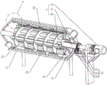
Fig. 1 is a schematic view of an overall structure according to an embodiment of the present invention.
Fig. 2 is a schematic diagram showing an internal structure of fig. 1.
Fig. 3 is a partially enlarged schematic view of a portion a in fig. 2.
Fig. 4 is a schematic view showing the positional relationship between the rake teeth and the inner cylinder in fig. 2.
FIG. 5 is a schematic view showing the connection between the helical stirring vanes and the auxiliary stirring impeller.
In the figure, 1, a frame; 2. an outer cylinder; 21. a positioning ring; 22. positioning a groove; 31. a sleeve; 32. a connecting rod; 33. an inner cylinder; 34. a drive device; 341. a second motor; 342. a driving gear; 343. a driven gear; 35. rake teeth; 4. an intermediate stirring device; 41. a rotating shaft; 42. a helical mixing blade; 43. a first motor; 5. an auxiliary stirring impeller; 51. a central shaft; 52. a blade.
Detailed Description
The present invention will be described in further detail with reference to the accompanying drawings.
Referring to fig. 1 and 2, a dry-mixed mortar mixing device disclosed in an embodiment of the present invention includes a frame 1, an outer cylinder 2, a sleeve 31, a connecting rod 32, an inner cylinder 33, a driving device 34, and an intermediate stirring device 4.
The outer cylinder 2 is fixed on the frame 1, two ends of the outer cylinder 2 are both in a cone-shaped arrangement, and one end of the outer cylinder 2 is provided with an opening along the axis direction; the sleeve 31 is rotatably arranged at one end of the opening of the outer cylinder 2, one end of the sleeve 31 extends into the outer cylinder 2, and the other end of the sleeve 31 extends out of the outer cylinder 2; the connecting rods 32 are provided with a plurality of connecting rods 32, the connecting rods 32 are all fixed at one end of the sleeve 31 extending into the outer cylinder 2, the connecting rods 32 are evenly distributed along the circumferential direction of the outer wall of the sleeve 31, each connecting rod 32 is arranged along the radial direction of the sleeve 31, and one end of each connecting rod 32 far away from the sleeve 31 is fixedly connected with the inner wall of the inner cylinder 33; the outer wall of interior barrel 33 and the smooth laminating of outer barrel 2, and can rotate outer barrel 2 relatively. The driving device 34 is fixedly arranged on the frame 1 and can control the sleeve 31 to rotate.
The middle stirring device 4 comprises a rotating shaft 41, a spiral stirring blade 42 and a first motor 43, the rotating shaft 41 is arranged in the sleeve 31 in a penetrating way and can rotate relative to the sleeve 31, two ends of the rotating shaft 41 respectively penetrate out of the sleeve 31, and one end of the rotating shaft 41 extends into the outer cylinder 2 and is rotationally connected with the bottom of the outer cylinder 2; the spiral stirring blade 42 is fixedly arranged on the rotating shaft 41; the first motor 43 is fixedly arranged on the frame 1, and an output shaft of the first motor 43 is connected with the rotating shaft 41 and can drive the rotating shaft 41 to rotate relative to the sleeve 31.
It should be noted that, both ends of the outer cylinder 2 are set to be cone-shaped, and the cone-shaped parts at both ends of the outer cylinder 2 are respectively provided with a feed inlet and a discharge outlet, and after the mixture is added from the feed inlet, the mixture falls into the inner cylinder 33, during the stirring process, the first motor 43 drives the rotating shaft 41 to rotate, and the helical stirring blade 42 stirs the mixture in the inner cylinder 33; meanwhile, the driving device 34 controls the sleeve 31 to rotate to drive the inner cylinder 33 to rotate, specifically, when the helical stirring blades 42 opposite to the rotation direction of the sleeve 31 and the rotation shaft 41 stir the mixture, the inner cylinder 33 rotates reversely to drive the mixture on the cylinder wall of the inner cylinder 33 to rotate, the mixture at the center of the inner cylinder 33 can be stirred by the helical stirring blades 42, and in the rotation process of the inner cylinder 33, the mixture close to the cylinder wall moves relative to the cylinder wall of the inner cylinder 33 under the action of gravity and collides with the mixture at the center of the inner cylinder 33 to mix, so that the mixing efficiency is effectively enhanced.
The driving device 34 includes a second motor 341, a driving gear 342 and a driven gear 343, the second motor 341 is fixed on the frame 1, the driving gear 342 is connected to an output shaft of the second motor 341, the driven gear 343 is fixed at one end of the sleeve 31 extending out of the outer cylinder 2, and the driving gear 342 is engaged with the driven gear 343.
The second motor 341 drives the driving gear 342 to rotate during operation, so as to drive the driven gear 343 and the sleeve 31 to rotate, and drive the sleeve 31 to rotate in a gear transmission manner, and the rotation of the inner cylinder 33 and the rotation of the intermediate stirring device 4 are not affected by each other. It should be understood that the drive 34 is not limited to a gear drive, but may take the form of a sprocket chain, belt drive, or the like.
Referring to fig. 3, a positioning ring 21 is fixed to one end of the inner wall of the outer cylinder 2, which is far away from the sleeve 31, along the circumferential direction, a positioning groove 22 is formed in a surface of one side of the positioning ring 21, which faces the sleeve 31, the positioning groove 22 is matched with the inner cylinder 33, and the end of the inner cylinder 33 is rotatably arranged in the positioning groove 22. When the driving device 34 works, one end, far away from the sleeve 31, of the inner barrel 33 can rotate in the positioning groove 22, the positioning groove 22 plays a supporting role in the inner barrel 33, the radial force of the inner barrel 33 is borne, one end of the inner barrel 33 is prevented from shaking, and the rotating process of the inner barrel 33 is made to be more stable.
Referring to fig. 4, rake teeth 35 are fixed on the inner wall of the inner cylinder 33, specifically, a plurality of rows of rake teeth 35 are uniformly distributed along the circumferential direction of the inner wall of the inner cylinder 33, and each row of rake teeth 35 is uniformly distributed along the direction parallel to the axis of the inner cylinder 33. When the mixture slides along the inner wall of the inner cylinder body 33, the mixture can generate friction collision with the rake teeth 35, the rake teeth 35 play a role in mixing the mixture, and the mixing efficiency is enhanced.
Further, on the circumferencial direction along the inner wall of inner cylinder 33, adjacent row of rake teeth 35 crisscross distribution, when the mixture slides down along inner cylinder 33 inner wall, can follow between the clearance of two adjacent rake teeth 35 and slide down, then just in time fall on next row of rake teeth 35, when the mixture slides in inner cylinder 33, all can obtain collision friction between each row of rake teeth 35, has further strengthened mixing efficiency.
Referring to fig. 5, a plurality of auxiliary stirring impellers 5 are fixed on the helical stirring blade 42, each auxiliary stirring impeller 5 includes a central shaft 51 and blades 52, the central shaft 51 is in a circular array with respect to the axis of the rotating shaft 41 and is fixedly connected with the helical stirring blade 42, and the blades 52 are uniformly distributed along the circumferential direction of the side wall of the central shaft 51. In the rotation process of middle agitating unit 4, helical mixing blade 42 mainly produces the circumferential driving force to the mixture, sets up supplementary impeller 5 and can produce the thrust of radial direction to the mixture around helical mixing blade 42, stirs the mixture to inside barrel 33 section of thick bamboo wall one side, plays the stirring effect to the mixture simultaneously, the inside mix process of barrel 33 including the mixture with higher speed.
Further, the blades 52 are arranged as arc-shaped pieces, so that the mixed materials are more easily attached to the blades 52 or slide along the blades 52, and the mixed materials move more smoothly among the blades 52.
The embodiment of this specific implementation mode is the preferred embodiment of the present invention, not limit according to this the utility model discloses a protection scope, so: all equivalent changes made according to the structure, shape and principle of the utility model are covered within the protection scope of the utility model.
Claims (7)
1. A dry-mixed mortar mixing device is characterized in that: comprises that
A frame (1);
the outer cylinder body (2) is fixed on the frame (1), and one end of the outer cylinder body is provided with an opening;
the sleeve (31) is rotatably arranged at the opening end of the outer barrel body (2), one end of the sleeve extends into the outer barrel body (2), and the other end of the sleeve extends out of the outer barrel body (2);
a plurality of connecting rods (32) which are fixed at one end of the sleeve (31) extending into the outer cylinder body (2) and are uniformly distributed along the circumferential direction of the outer wall of the sleeve (31);
the inner cylinder (33) is fixed at the end part of the connecting rod (32) far away from the sleeve (31), and the outer wall of the inner cylinder (33) is smoothly attached to the outer cylinder (2);
the driving device (34) is arranged on the rack (1), is connected with the sleeve (31) and is used for controlling the sleeve (31) to rotate; and
the middle stirring device (4) comprises a rotating shaft (41) rotatably arranged in the outer cylinder body (2), a spiral stirring blade (42) arranged on the rotating shaft (41) and a first motor (43) arranged on the rack (1);
the rotating shaft (41) is coaxial with the sleeve (31) and can rotate relative to the sleeve (31), and one end of the rotating shaft (41) penetrates out of the outer cylinder body (2) and then is connected with the first motor (43).
2. The dry-mixed mortar mixing device according to claim 1, characterized in that: the drive device (34) comprises
The second motor (341) is arranged on the frame (1);
the driving gear (342) is connected with the output end of the second motor (341); and
the driven gear (343) is arranged at one end, extending out of the outer cylinder (2), of the sleeve (31), and the driving gear (342) is meshed with the driven gear (343) and can drive the driven gear (343) and the sleeve (31) to rotate.
3. The dry-mixed mortar mixing device according to claim 1, characterized in that: the inner wall of the inner cylinder body (33) is uniformly provided with a plurality of rows of rake teeth (35) along the circumferential direction, and each row of rake teeth (35) are uniformly distributed along the direction parallel to the axis of the inner cylinder body (33).
4. The dry-mixed mortar mixing device according to claim 3, characterized in that: in the circumferential direction of the inner cylinder (33), the rake teeth (35) of adjacent rows are distributed in a staggered manner.
5. The dry-mixed mortar mixing device according to claim 1, characterized in that: one end of the inner wall of the outer barrel body (2) far away from the sleeve (31) is provided with a positioning ring (21) along the circumferential direction, the positioning groove (22) is formed in the surface of one side of the positioning ring (21) facing the sleeve (31), and one end of the inner barrel body (33) far away from the sleeve (31) is rotatably arranged in the positioning groove (22).
6. The dry-mixed mortar mixing device according to claim 1, characterized in that: a plurality of auxiliary stirring impellers (5) are arranged on the spiral stirring blade (42);
the auxiliary stirring impeller (5) comprises a central shaft (51) which is in a circular array relative to the axis of the rotating shaft (41) and a plurality of blades (52) which are uniformly distributed along the circumferential direction of the side wall of the central shaft (51).
7. The dry-mixed mortar mixing device according to claim 6, characterized in that: the blades (52) are arc-shaped pieces.
Priority Applications (1)
| Application Number | Priority Date | Filing Date | Title |
|---|---|---|---|
| CN202021162296.4U CN212978757U (en) | 2020-06-20 | 2020-06-20 | Dry-mixed mortar mixing equipment |
Applications Claiming Priority (1)
| Application Number | Priority Date | Filing Date | Title |
|---|---|---|---|
| CN202021162296.4U CN212978757U (en) | 2020-06-20 | 2020-06-20 | Dry-mixed mortar mixing equipment |
Publications (1)
| Publication Number | Publication Date |
|---|---|
| CN212978757U true CN212978757U (en) | 2021-04-16 |
Family
ID=75424214
Family Applications (1)
| Application Number | Title | Priority Date | Filing Date |
|---|---|---|---|
| CN202021162296.4U Active CN212978757U (en) | 2020-06-20 | 2020-06-20 | Dry-mixed mortar mixing equipment |
Country Status (1)
| Country | Link |
|---|---|
| CN (1) | CN212978757U (en) |
-
2020
- 2020-06-20 CN CN202021162296.4U patent/CN212978757U/en active Active
Similar Documents
| Publication | Publication Date | Title |
|---|---|---|
| CN211662345U (en) | Concrete mixing device | |
| CN107855049A (en) | A kind of efficient mixer | |
| CN212651718U (en) | Thermosetting powder coating mixing device | |
| CN109012286A (en) | Ratio for architectural engineering feeds mixing apparatus | |
| CN212978757U (en) | Dry-mixed mortar mixing equipment | |
| CN211659859U (en) | Compound circulating device of pumping agent | |
| CN201279445Y (en) | Eddy powder mixer | |
| CN111347559A (en) | Concrete mixer | |
| CN111775327A (en) | Agitating unit and concrete mixer | |
| CN214973448U (en) | Novel bulk blend fertilizer unloading device | |
| CN210389647U (en) | High-efficient cement mortar mixer | |
| CN214819674U (en) | High-efficient dry-mixed mortar mixes machine | |
| CN214925696U (en) | High-efficiency cement mixer | |
| CN213408355U (en) | Tiltable mixing device for food processing | |
| CN214187787U (en) | Novel stirring machine | |
| CN212188657U (en) | Powder mixer | |
| CN211333946U (en) | Agitating unit is used in concrete processing | |
| CN211842604U (en) | Automatic feeding device of concrete mixing plant | |
| CN211842588U (en) | Commercial concrete stirring is with mixing machine | |
| CN211279136U (en) | Cylinder-shaft integrated cement stirring device based on planetary gear transmission principle | |
| CN106925176A (en) | A kind of biaxial rneader | |
| CN211164629U (en) | Premixed mortar mixer | |
| CN210552132U (en) | Two vertical scroll high performance concrete mixer | |
| CN208978015U (en) | A kind of automatic mortar stirring device | |
| CN207972134U (en) | A kind of twin shaft concrete central mix plant |
Legal Events
| Date | Code | Title | Description |
|---|---|---|---|
| GR01 | Patent grant | ||
| GR01 | Patent grant |