CN212971663U - Atomization assembly, heating atomization device and electronic equipment - Google Patents
Atomization assembly, heating atomization device and electronic equipment Download PDFInfo
- Publication number
- CN212971663U CN212971663U CN202021175559.5U CN202021175559U CN212971663U CN 212971663 U CN212971663 U CN 212971663U CN 202021175559 U CN202021175559 U CN 202021175559U CN 212971663 U CN212971663 U CN 212971663U
- Authority
- CN
- China
- Prior art keywords
- assembly
- atomizing
- heating
- shell
- base
- Prior art date
- Legal status (The legal status is an assumption and is not a legal conclusion. Google has not performed a legal analysis and makes no representation as to the accuracy of the status listed.)
- Active
Links
Images


Landscapes
- Disinfection, Sterilisation Or Deodorisation Of Air (AREA)
Abstract
The utility model provides an atomization component, heating atomizing device and electronic equipment. The atomization assembly comprises a base, a heating assembly, a blocking plate and a shell, wherein the heating assembly is arranged on the base, and the shell covers the base and the heating assembly; the shell is provided with a through hole, the atomizing assembly is also provided with a gas path for gas flow circulation, and the gas path is communicated with the through hole; the separation plate is provided with a separation part and a plurality of air holes positioned around the separation part, and the separation part is blocked on the air path and is opposite to the through hole so that the air path is communicated with the through hole through the air holes. The utility model discloses technical scheme has effectively solved the liquid object and has sprayed the phenomenon to the heating atomizing device outside.
Description
Technical Field
The utility model relates to an electronic equipment technical field especially relates to an atomization component, heating atomizing device and electronic equipment.
Background
Currently, more and more atomizers are on the market. Atomizers typically include a heated atomizer having a liquid object stored therein, and an atomizing assembly in the heated atomizer for heating the liquid object to generate an aerosol. In the process of heating the liquid object, the atomization assembly may spray the liquid object to the air outlet of the heating atomization device due to the high temperature.
Some atomizers have a microporous membrane near the air outlet to prevent liquid objects from being ejected from the air outlet. But the microporous membrane has small air permeability, so that the flow of the aerial fog is not facilitated. Meanwhile, if the microporous membrane is fixedly arranged in the atomizer, in the long-term use process, liquid objects are easily mixed with dust and the like to form a mixture to block micropores, so that the air path is blocked.
Therefore, the ejection phenomenon of the liquid object is a problem to be solved.
SUMMERY OF THE UTILITY MODEL
The utility model provides an atomization component, heating atomizing device and electronic equipment through set up the injection phenomenon of baffler in order to solve liquid object in atomization component.
In a first aspect, an embodiment of the present invention provides an atomizing assembly, which includes a base, a heating assembly, a blocking plate, and a housing, wherein the heating assembly is disposed on the base, and the housing is covered on the base and the heating assembly; the shell is provided with a through hole, the atomization assembly is also provided with a gas path for gas flow circulation, and the gas path is communicated with the through hole; the blocking plate is provided with a blocking part and a plurality of air holes positioned around the blocking part, and the blocking part blocks the air path and is opposite to the through hole, so that the air path is communicated with the through hole through the air holes.
Optionally, the blocking plate is clamped between the outer shell and the base and located on one side of the heating assembly away from the base; the through hole is arranged on one side of the shell facing the heating assembly.
Optionally, the air path is arranged on the heating assembly, and one surface of the heating assembly facing the housing and one surface of the heating assembly facing the base are communicated to form the air path.
Optionally, there is one air passage, and the air passage is disposed in the center of the heating assembly; the blocking part is arranged in the center of the blocking plate, and the air holes are symmetrically arranged around the blocking part.
Optionally, the heating element includes liquid guide cotton and heliciform heater strip, the cotton parcel of liquid guide the heater strip, the gas circuit form in the middle of the heater strip.
Optionally, the barrier plate is hardware.
In a second aspect, an embodiment of the present invention provides a heating and atomizing device, the heating and atomizing device includes:
the atomization device comprises a shell, an atomization tube and an atomization assembly, wherein the atomization assembly and the atomization tube are accommodated in the shell; one end of the atomization tube is connected with the shell, the other end of the atomization tube is sleeved on the shell, and the atomization assembly is detachably mounted in the shell; the atomization assembly comprises a base, a heating assembly, a blocking plate and a shell, wherein the heating assembly is arranged on the base, and the shell is covered on the base and the heating assembly; the shell is provided with a through hole, the atomization assembly is also provided with a gas path for gas flow circulation, and the gas path is communicated with the through hole; the blocking plate is provided with a blocking part and a plurality of air holes positioned around the blocking part, and the blocking part blocks the air path and is opposite to the through hole, so that the air path is communicated with the through hole through the air holes.
Optionally, the casing includes the gas outlet, the pipe wall of atomizing pipe encloses to establish and forms the atomizing chamber, the base is kept away from the air inlet has been seted up to one side of heating element, the air inlet the gas circuit the atomizing chamber and the gas outlet intercommunication forms the air flue.
Optionally, a liquid storage cavity is defined between the housing and the atomizing pipe and between the housing and the atomizing assembly, and the liquid storage cavity is used for storing liquid objects; the base with the shell is equipped with the drain hole, liquid object passes through the drain hole flows into in the atomizing subassembly, heating element is used for to liquid object heats in order to form aerial fog.
In a third aspect, an embodiment of the present invention provides an electronic device, where the electronic device includes a power supply device and a heating and atomizing device, and the heating and atomizing device is electrically connected to the power supply device; the heating and atomizing device comprises a shell, an atomizing pipe and an atomizing assembly, wherein the atomizing assembly and the atomizing pipe are accommodated in the shell; one end of the atomization tube is connected with the shell, the other end of the atomization tube is sleeved on the shell, and the atomization assembly is detachably mounted in the shell.
Above-mentioned atomization component, heating atomizing device and electronic equipment through set up the baffler in atomization component, and the separation portion of baffler just right with the through-hole for when heating component heated liquid object, because the higher liquid object that erupts to the through-hole direction of temperature is blockked by separation portion, avoided liquid object to erupt and scald the user from the through-hole.
Drawings
Fig. 1 is an exploded schematic view of an atomizing assembly provided in an embodiment of the present invention.
Fig. 2 is a perspective view of an atomizing assembly provided in an embodiment of the present invention.
Fig. 3 is a cross-sectional view of an atomizing assembly provided in an embodiment of the present invention.
Fig. 4 is a top view of an atomizing assembly provided in an embodiment of the present invention.
Fig. 5 is an exploded schematic view of a heating and atomizing device provided in an embodiment of the present invention.
Fig. 6 is a sectional view of a heating and atomizing device according to an embodiment of the present invention.
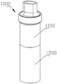
Fig. 7 is a perspective view of an electronic device according to an embodiment of the present invention.
Wherein, each element in the figure is marked as follows:
1000-electronic equipment, 1100-heating atomization device, 1200-power supply device, 100-atomization assembly, 10-base, 11-air inlet, 12-seat, 13-coaming, 130-containing space, 20-heating assembly, 21-liquid guide cotton, 22-air path, 30-baffle plate, 31-baffle part, 32-air hole, 40-shell, 41-through hole, 42-liquid guide hole, 200-shell, 201-air outlet, 300-atomization tube, 301-atomization cavity and 400-liquid storage cavity.
Detailed Description
In the description of the present invention, it is to be understood that the terms "length", "width", "upper", "lower", "front", "rear", "left", "right", "vertical", "horizontal", "top", "bottom", "inner", "outer", and the like indicate orientations or positional relationships based on those shown in the drawings, and are merely for convenience of description and simplicity of description, and do not indicate or imply that the device or element being referred to must have a particular orientation, be constructed and operated in a particular orientation, and thus, should not be construed as limiting the present invention.
Furthermore, the terms "first", "second" and "first" are used for descriptive purposes only and are not to be construed as indicating or implying relative importance or implicitly indicating the number of technical features indicated. Thus, a feature defined as "first" or "second" may explicitly or implicitly include one or more of that feature. In the description of the present invention, "a plurality" means two or more unless specifically limited otherwise.
In the present invention, unless otherwise expressly stated or limited, the terms "mounted," "connected," and "fixed" are to be construed broadly and may, for example, be fixedly connected, detachably connected, or integrally formed; can be mechanically or electrically connected; either directly or indirectly through intervening media, either internally or in any other relationship. The specific meaning of the above terms in the present invention can be understood according to specific situations by those skilled in the art.
For a clearer and more accurate understanding of the present invention, reference will now be made to the following detailed description taken in conjunction with the accompanying drawings. Description of drawings the accompanying drawings illustrate examples of embodiments of the present invention, in which like reference numerals refer to like elements. It is to be understood that the drawings are not to scale as the actual practice of the invention, but are for illustrative purposes and are not drawn to scale.
Please refer to fig. 1 to fig. 6 in combination, which are an atomizing assembly, a heating and atomizing device, and an electronic apparatus according to an embodiment of the present invention. The atomizing assembly 100 is used for heating a liquid object (not shown) stored in the heated atomizing device 1100 to form an aerosol. Liquid objects include, but are not limited to, tobacco tar, mosquito repellent, water, and the like.
Please refer to fig. 1, fig. 2 and fig. 3, which are an exploded schematic view of an atomizing assembly, a perspective view of the atomizing assembly, and a cross-sectional view of the atomizing assembly according to an embodiment of the present invention. The atomizing assembly 100 includes a base 10, a heating assembly 20, a baffle plate 30, and a housing 40. Wherein, the heating element 20 is disposed on the base 10, and the housing 40 covers the base 10 and the heating element 20. Specifically, the base 10 includes a seat 12, and a shroud 13 provided on a side of the seat 12 facing the housing 40. In this embodiment, the shroud 13 includes two pieces, and has an arc plate shape. The two enclosing plates 13 symmetrically extend from the edge of the seat 12 towards one side of the shell 40 towards the shell 40. In some possible embodiments, the number, shape and position of the enclosing plates 13 on the seat 12 are not limited thereto, and are not described herein. The two enclosing plates 13 enclose to form an accommodating space 130, and the heating assembly 20 is accommodated in the accommodating space 130. The housing 40 is provided with a through hole 41, and the through hole 41 is provided at a side of the housing 40 facing the heating assembly 20. Specifically, the through hole 41 is provided in the center of one end of the housing 40 away from the base 10. One end of the housing 40 facing the base 10 abuts against the base 10. The atomizing assembly 100 further forms a gas path 22 for the gas flow, and the gas path 22 communicates with the through hole 41. Specifically, the air passage 22 is provided to the heating assembly 20. The side of the heating assembly 20 facing the housing 40 is communicated with the side of the heating assembly 20 facing the base 10 to form an air passage 22. In the present embodiment, there is one air passage 22, and the air passage 22 is disposed in the center of the heating element 20. Specifically, the heating assembly 20 includes a liquid guide cotton 21 and a spiral heating wire (not shown). The liquid guide cotton 21 wraps the heating wires, and the air path 22 is formed in the middle of the heating wires. In some possible embodiments, the number of the air passages 22 and the positions of the air passages provided on the heating element 20 are not limited thereto, and are not described herein again.
Please refer to fig. 1 and fig. 4, which are an exploded schematic view of an atomizing assembly and a top view of the atomizing assembly according to an embodiment of the present invention. The baffle plate 30 is sandwiched between the housing 40 and the base 10 and is located on the side of the heating assembly 20 away from the base 10. Specifically, the blocking plate 30 is provided at an end of the apron 13 remote from the seat 12. The blocking plate 30 is a circular thin plate, and the size of the blocking plate 30 is larger than the size of a circle surrounded by one end, far away from the seat 12, of the coaming 13. When the housing 40 is covered on the base 10, the inner wall of the housing 40 facing the seat 12 is just abutted against the surface of the blocking plate 30 facing the housing 40, so that the blocking plate 30 is fixedly installed in the atomizing assembly 100. The blocking plate 30 has a blocking portion 31 and a plurality of air holes 32 around the blocking portion 31. Specifically, the blocking portion 31 blocks the air path 22 and is opposite to the through hole 41, so that the air path 22 communicates with the through hole 41 through the plurality of air holes 32. In the present embodiment, the blocking portion 31 is disposed at the center of the blocking plate 30, and the size of the blocking portion 31 is matched with the size of the cross section of the through hole 41. Six air holes 32 are provided, and the six air holes 32 are symmetrically provided around the blocking portion 31. In some possible embodiments, the size of the blocking portion 31 and the position of the blocking portion 31 disposed on the blocking plate 30 are not limited thereto, and the number of the air holes 32 and the position of the air holes 32 disposed on the blocking plate 30 are also not limited thereto, and are not described herein again. Wherein, the baffle plate 30 is a hardware. In some possible embodiments, the barrier plate 30 may be made of, but is not limited to, a material having heat resistance, hardness, and the like.
In the above embodiment, the blocking plate 30 is disposed in the atomizing assembly 100, and the blocking portion 31 of the blocking plate 30 is directly opposite to the through hole 41, so that when the heating assembly 20 heats the liquid object, the liquid object ejected toward the through hole 41 due to the higher temperature is blocked by the blocking portion 31, and the liquid object is prevented from being ejected from the through hole 41 and scalding the user.
Please refer to fig. 5 and fig. 6, which are an exploded schematic view of a heating and atomizing device and a cross-sectional view of the heating and atomizing device according to an embodiment of the present invention. The heated atomizing device 1100 includes a housing 200, an atomizing tube 300, and an atomizing assembly 100. The specific structure of the atomizing assembly 100 refers to the above-described embodiments. The atomizing assembly 100 and the atomizing tube 300 are housed in the housing 200. Specifically, one end of the atomization tube 300 is connected to the housing 200, and the other end of the atomization tube 300 is sleeved on the outer shell 40 of the atomization assembly 100. The atomization tube 300 and the atomization assembly 100 are fixedly mounted at the center of the housing 200, and the atomization assembly 100 is detachably mounted in the housing 200.
Referring again to fig. 1, a reservoir 400 is defined between the housing 200 and the atomizing tube 300 and the atomizing assembly 100. The reservoir 400 is used to store a liquid object. The base 10 and the housing 40 are provided with a liquid guide hole 42, and the liquid guide hole 42 communicates the liquid storage chamber 400 with the air passage. The liquid object flows into the atomizing assembly 100 through the liquid guide hole 42, is absorbed by the liquid guide cotton 21 of the heating assembly 20, and is heated by the heating wire to form an aerosol.
Since the heating and atomizing device 1100 adopts all the technical solutions of all the embodiments, the heating and atomizing device 1100 has at least all the advantages brought by the technical solutions of the embodiments. In addition, the atomizing assembly 100 is detachably mounted in the housing 200, so that the atomizing assembly 100 can be replaced, and the phenomenon that the air hole 32 of the blocking plate 30 is blocked due to the fact that the blocking plate 30 is not replaced in the long-term use process of the heating and atomizing device 1100 can be effectively prevented.
Please refer to fig. 7, which is a perspective view of an electronic device according to an embodiment of the present invention. The electronic apparatus 1000 includes a power supply device 1200 and a heating atomization device 1100. The heating and atomizing device 1100 is electrically connected to the power supply device 1200. The specific structure of the heating and atomizing device 1100 refers to the above embodiments, and since the electronic device 1000 adopts all technical solutions of all the above embodiments, the electronic device 1000 at least has all beneficial effects brought by the technical solutions of the above embodiments, and details are not repeated here.
It will be apparent to those skilled in the art that various changes and modifications may be made without departing from the spirit and scope of the invention. Thus, to the extent that such modifications and variations fall within the scope of the invention and the equivalent techniques thereof, it is intended that the present invention also encompass such modifications and variations.
The above description is only for the purpose of illustrating the preferred embodiments of the present invention and is not to be construed as limiting the scope of the present invention, therefore, the present invention is not limited by the following claims.
Claims (10)
1. An atomization assembly is characterized by comprising a base, a heating assembly, a blocking plate and a shell, wherein the heating assembly is arranged on the base, and the shell is covered on the base and the heating assembly; the shell is provided with a through hole, the atomization assembly is also provided with a gas path for gas flow circulation, and the gas path is communicated with the through hole; the blocking plate is provided with a blocking part and a plurality of air holes positioned around the blocking part, and the blocking part blocks the air path and is opposite to the through hole, so that the air path is communicated with the through hole through the air holes.
2. The atomizing assembly of claim 1, wherein the baffle plate is sandwiched between the housing and the base on a side of the heating assembly remote from the base; the through hole is arranged on one side of the shell facing the heating assembly.
3. The atomizing assembly of claim 1, wherein the air passage is disposed in the heating assembly, and a communication between a side of the heating assembly facing the housing and a side of the heating assembly facing the base forms the air passage.
4. The atomizing assembly of claim 3, wherein there is one gas passage, and the gas passage is disposed in the center of the heating assembly; the blocking part is arranged in the center of the blocking plate, and the air holes are symmetrically arranged around the blocking part.
5. The atomizing assembly of claim 3, wherein the heating assembly comprises a liquid guide cotton and a spiral heating wire, the liquid guide cotton wraps the heating wire, and the gas path is formed in the middle of the heating wire.
6. The atomizing assembly of claim 1, wherein the baffle plate is hardware.
7. A heating atomizing device, characterized in that the heating atomizing device comprises:
a housing, an atomizing tube, and the atomizing assembly of any of claims 1-6, said atomizing assembly and said atomizing tube being housed within said housing; one end of the atomization tube is connected with the shell, the other end of the atomization tube is sleeved on the shell, and the atomization assembly is detachably mounted in the shell.
8. The heating atomizing device of claim 7, wherein the housing includes an air outlet, the wall of the atomizing tube defines an atomizing chamber, the base includes an air inlet on a side thereof away from the heating assembly, and the air inlet, the air passage, the atomizing chamber and the air outlet are communicated to form an air passage.
9. The heated atomizing device of claim 7, wherein a reservoir is defined between the housing and the atomizing tube and the atomizing assembly, the reservoir being configured to store a liquid substance; the base with the shell is equipped with the drain hole, liquid object passes through the drain hole flows into in the atomizing subassembly, heating element is used for to liquid object heats in order to form aerial fog.
10. An electronic device, the electronic device including a power supply apparatus, the electronic device further comprising: the heating atomizing device according to any one of claims 7 to 9, which is electrically connected to the power supply device.
Priority Applications (1)
| Application Number | Priority Date | Filing Date | Title |
|---|---|---|---|
| CN202021175559.5U CN212971663U (en) | 2020-06-23 | 2020-06-23 | Atomization assembly, heating atomization device and electronic equipment |
Applications Claiming Priority (1)
| Application Number | Priority Date | Filing Date | Title |
|---|---|---|---|
| CN202021175559.5U CN212971663U (en) | 2020-06-23 | 2020-06-23 | Atomization assembly, heating atomization device and electronic equipment |
Publications (1)
| Publication Number | Publication Date |
|---|---|
| CN212971663U true CN212971663U (en) | 2021-04-16 |
Family
ID=75424352
Family Applications (1)
| Application Number | Title | Priority Date | Filing Date |
|---|---|---|---|
| CN202021175559.5U Active CN212971663U (en) | 2020-06-23 | 2020-06-23 | Atomization assembly, heating atomization device and electronic equipment |
Country Status (1)
| Country | Link |
|---|---|
| CN (1) | CN212971663U (en) |
-
2020
- 2020-06-23 CN CN202021175559.5U patent/CN212971663U/en active Active
Similar Documents
| Publication | Publication Date | Title |
|---|---|---|
| EP4039112B1 (en) | Atomizer and electronic atomization device | |
| WO2020151376A1 (en) | Electronic cigarette having two air passages | |
| CN111134364A (en) | Flat atomizing device and flat electronic cigarette with the same | |
| CN114617306A (en) | Power supply module and electronic atomization device | |
| WO2022161035A1 (en) | Atomizer with atomization core having protection cover | |
| CN112931972A (en) | Atomizer with atomizing cavity at inner bottom of atomizing core | |
| CN212814261U (en) | Electronic atomization device and atomizer thereof | |
| CN114947219A (en) | Electron smog spinning disk atomiser with soft atomizing core | |
| CN215958369U (en) | Atomizer and aerosol-generating device | |
| CN219460368U (en) | Atomizer and electronic atomization device | |
| CN216853796U (en) | Atomizer and aerosol generating device | |
| CN214340096U (en) | Atomizing core piece of atomizing device, atomizing device and electronic atomizing equipment | |
| CN211153811U (en) | Atomizing device and electron cigarette | |
| CN214962605U (en) | Atomizer with atomizing cavity arranged at bottom in atomizing core | |
| CN219270149U (en) | Electronic atomizing device capable of switching tastes | |
| CN212971663U (en) | Atomization assembly, heating atomization device and electronic equipment | |
| CN219288750U (en) | Sliding connection type electronic cigarette | |
| CN217826779U (en) | Electronic atomization device and atomizer | |
| CN215455411U (en) | Atomizing device and aerosol-generating device | |
| CN220529273U (en) | Atomizers and electronic atomization devices | |
| CN215224796U (en) | Aerosol generating device with improved airflow channel | |
| CN111838771A (en) | Electronic cigarette and atomization device thereof | |
| CN218043796U (en) | Heating module, atomizing component and electronic atomizer | |
| CN216147226U (en) | Atomizer and aerosol-generating device | |
| CN214340112U (en) | Atomization assembly and atomization device with same |
Legal Events
| Date | Code | Title | Description |
|---|---|---|---|
| GR01 | Patent grant | ||
| GR01 | Patent grant | ||
| CP03 | Change of name, title or address | ||
| CP03 | Change of name, title or address |
Address after: 518000 floor 1, floor 2, floor 3, floor 4 and floor 5 of plant 3, antuoshan high tech Industrial Park, Shaer community, Shajing street, Bao'an District, Shenzhen, Guangdong Patentee after: Shenzhen skol Technology Co.,Ltd. Address before: C1001, C501, a901, No.1, Tianyang 2nd Road, Dongfang community, Songgang street, Bao'an District, Shenzhen, Guangdong 518000 Patentee before: SHENZHEN SKE TECHNOLOGY Co.,Ltd. |