Higher scaffold for building of security
Technical Field
The utility model belongs to the technical field of building engineering, specifically be a higher scaffold for building of security.
Background
Scaffold frame refers to the job site and operates and solve various supports that perpendicular and horizontal transportation set up for the workman, be the general term in the building world, it is the outer wall to use more on the building site, interior decoration or the higher unable direct construction's of floor height place, mainly for constructor upper and lower do alive or peripheral safety net maintenance and high altitude installation component, but scaffold frame for building is mostly by the support now, steel pipe and fastener etc. are mutually connected and are formed, installation and dismantlement process are wasted time and energy, the suitability is lower, not only seriously influence the progress of construction, influence the time limit for a project, and frequently install and the in-process of dismantling at the high altitude, lead to the accident to take place easily.
SUMMERY OF THE UTILITY MODEL
Technical problem to be solved
In order to overcome prior art's above-mentioned defect, the utility model provides a higher scaffold for building of security has solved present scaffold for building and has mostly formed by mutual joint such as support, steel pipe and fastener, and the installation is wasted time and energy with the dismantlement process, and the suitability is lower, not only seriously influences the progress of construction, influences the time limit for a project, frequently installs and dismantles the in-process at the high altitude moreover, leads to the problem that the accident takes place easily.
(II) technical scheme
In order to achieve the above object, the utility model provides a following technical scheme: a scaffold for building with high safety comprises a base, wherein vertical plates are arranged on the left side and the right side of the upper surface of the base, two sliding grooves are arranged on the opposite surfaces of the two vertical plates, sliding blocks are connected in the sliding grooves in a sliding mode, the opposite surfaces corresponding to the two sliding blocks are respectively and fixedly connected with the left side surface and the right side surface of the supporting plate, the left side and the right side of the lower surface of the supporting plate are respectively and fixedly connected with the upper surfaces of the two supporting frames, the lower surfaces of the supporting frames are fixedly connected with the upper surfaces of the supporting blocks, the lower surfaces of the supporting blocks are fixedly connected with the upper surface of the base, the opposite surfaces of the two supporting frames are respectively fixedly connected with the left side surface and the right side surface of the two connecting rods, the back surfaces of the two connecting rods are in threaded connection with the same first threaded rod, the back of the first threaded rod is fixedly connected with an output shaft of the motor, and the lower surface of the motor is fixedly connected with the upper surface of the placing plate.
As a further aspect of the present invention: the lower surface of the placing plate is fixedly connected with the upper surface of the telescopic rod, and the lower surface of the telescopic rod is fixedly connected with the upper surface of the base.
As a further aspect of the present invention: all be provided with the baffle around the backup pad upper surface, the front of first threaded rod is provided with the stopper.
As a further aspect of the present invention: the upper surface threaded connection of base has four second threaded rods, the top of second threaded rod and the lower fixed surface of carousel are connected.
As a further aspect of the present invention: the upper surface of the rotary disc is provided with a rotary handle, and the bottom end of the second threaded rod is fixedly connected with the upper surface of the earth drilling device.
As a further aspect of the present invention: the ground drilling device is located in a groove formed in the lower surface of the base, and universal wheels are arranged at four corners of the lower surface of the base.
(III) advantageous effects
Compared with the prior art, the beneficial effects of the utility model reside in that:
1. this higher scaffold for building of security, through setting up first threaded rod, the support frame, motor and backup pad, when the staff need use this scaffold for the construction operation, the back in the backup pad is stood to the staff, open the motor, the motor drives first threaded rod and rotates, make two connecting rods do the motion that is close to each other at first threaded rod outer wall, it contracts to drive the support frame, the support frame promotes the backup pad upward movement, make this scaffold can adjust the height of backup pad according to actual conditions, increase the suitability of this scaffold, avoid frequently installing and the in-process of dismantling at the high altitude, lead to unexpected the emergence.
2. This higher scaffold for building of security bores ground ware, second threaded rod and carousel through setting up, when the staff need use this scaffold, moves suitable position with this scaffold earlier, through the rotatory carousel of handle of carousel upper surface for the carousel drives through the second threaded rod and bores ground ware and rotate, inserts ground with boring ground ware, makes this scaffold can't remove, improves the security of this scaffold.
3. This higher scaffold for building of security through setting up universal wheel, spout and slider, under the cooperation of spout and slider for when the staff removes the backup pad, it is more stable, set up the universal wheel, makes things convenient for the staff to remove this scaffold.
Drawings
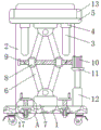
Fig. 1 is a schematic structural view of a front view section of the present invention;
FIG. 2 is a schematic structural diagram of a left side view section of the present invention;
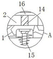
fig. 3 is an enlarged schematic structural view at a position a of the present invention;
in the figure: the device comprises a base 1, a vertical plate 2, a sliding groove 3, a sliding block 4, a supporting plate 5, a supporting frame 6, a supporting block 7, a connecting rod 8, a first threaded rod 9, a motor 10, a placing plate 11, a telescopic rod 12, a baffle 13, a second threaded rod 14, a ground drilling device 15, a rotary table 16 and a universal wheel 17.
Detailed Description
The technical solution of the present patent will be described in further detail with reference to the following embodiments.
As shown in fig. 1-3, the utility model provides a technical solution: a scaffold for buildings with higher safety comprises a base 1, wherein vertical plates 2 are arranged on the left side and the right side of the upper surface of the base 1, two sliding grooves 3 are arranged on the opposite surfaces of the two vertical plates 2, sliding blocks 4 are connected in the sliding grooves 3 in a sliding manner, the device is more stable when a supporting frame 6 pushes a supporting plate 5 to move up and down by arranging the sliding grooves 3 and the sliding blocks 4, the safety of the device is improved, the opposite surfaces corresponding to the two sliding blocks 4 are fixedly connected with the left side surface and the right side surface of the supporting plate 5 respectively, the left side and the right side of the lower surface of the supporting plate 5 are fixedly connected with the upper surfaces of two supporting frames 6 respectively, the lower surface of the supporting frame 6 is fixedly connected with the upper surface of a supporting block 7, the lower surface of the supporting block 7 is fixedly connected with the upper surface of the base 1, the opposite surfaces of, the back of first threaded rod 9 and the output shaft fixed connection of motor 10, through setting up motor 10, connecting rod 8 and first threaded rod 9, when motor 10 drives first threaded rod 9 and rotates, two connecting rods 8 are close to each other or the motion of keeping away from each other at 9 outer walls of first threaded rod for support frame 6 drives backup pad 5 and reciprocates, improves the suitability of this scaffold frame, the lower surface of motor 10 with place the last fixed surface of board 11 and be connected.
Specifically, as shown in fig. 2, the lower surface of the placing plate 11 is fixedly connected with the upper surface of the telescopic rod 12, the lower surface of the telescopic rod 12 is fixedly connected with the upper surface of the base 1, the placing plate 11 and the telescopic rod 12 are arranged, the placing plate 11 provides a supporting effect for the motor 10, the motor 10 cannot rotate, the motor 10 can adjust the height of the motor 10 along with the heights of the first threaded rod 9 and the support frame 6 under the effect of the telescopic rod 12, and the scaffold can work normally.
Specifically, as shown in fig. 2 and 3, baffle 13 all is provided with around the 5 upper surfaces of backup pad, the front of first threaded rod 9 is provided with the stopper, through setting up the stopper, avoid first threaded rod 9 when rotatory, connecting rod 8 breaks away from first threaded rod 9, improve the security of this scaffold, the upper surface threaded connection of base 1 has four second threaded rods 14, through setting up second threaded rod 14, when making second threaded rod 14 rotate, can drive and bore ground ware 15 and reciprocate, ensure to bore ground ware 15 and normally work, the top of second threaded rod 14 and the lower fixed surface of carousel 16 are connected.
Specifically, as shown in fig. 1 and 3, the upper surface of the rotary table 16 is provided with a rotating handle, and through the arrangement of the rotary table 16 and the rotating handle, the second threaded rod 14 can be rotated by a worker more conveniently and quickly, the bottom end of the second threaded rod 14 is fixedly connected with the upper surface of the ground drilling device 15, the ground drilling device 15 is located in a groove formed in the lower surface of the base 1, through the arrangement of the ground drilling device 15, when the scaffold is required to be used by the worker, the rotary table 16 can be rotated, the ground drilling device 15 is driven to rotate through the second threaded rod 14, the ground drilling device 15 is inserted into the ground, the ground drilling device 15 is fixed to the scaffold, the safety of the scaffold is improved, and the four corners of the lower surface of the base 1 are provided with universal wheels 17.
The utility model discloses a theory of operation does:
s1, when the scaffold is needed to be used by a worker, the scaffold is moved to a proper position, the turntable 16 is rotated clockwise through the handle on the upper surface of the turntable 16, so that the turntable 16 drives the second threaded rod 14 and the ground drilling device 15 to rotate, the ground drilling device 15 is rotated to the ground, and the scaffold is fixed;
s2, a worker turns on the motor 10 to enable the motor 10 to rotate clockwise, the motor 10 drives the first threaded rod 9 to rotate clockwise, the two connecting rods 8 on the outer wall of the first threaded rod 9 move away from each other, the first threaded rod 9 drives the supporting plate 5 to move downwards, and meanwhile the placing plate 11 drives the motor 10 to synchronously move downwards under the action of the telescopic rod 12;
s3, when the support plate 5 descends to a proper position, a worker stands on the support plate 5, the motor 10 is turned on, the motor 10 drives the first threaded rod 9 to rotate anticlockwise, the two connecting rods 8 on the outer wall of the first threaded rod 9 move close to each other, under the cooperation of the first threaded rod 9 and the sliding block 4, the support plate 5 pushes the worker to move upwards, and when the support plate 5 moves to the proper position, the motor 10 is turned off.
In the description of the present invention, it is to be noted that, unless otherwise explicitly specified or limited, the terms "mounted," "connected," and "connected" are to be construed broadly, and may be, for example, fixedly connected, detachably connected, or integrally connected; can be mechanically or electrically connected; they may be connected directly or indirectly through intervening media, or they may be interconnected between two elements. The specific meaning of the above terms in the present invention can be understood by those of ordinary skill in the art through specific situations.
Although the preferred embodiments of the present patent have been described in detail, the present patent is not limited to the above embodiments, and various changes can be made without departing from the spirit of the present patent within the knowledge of those skilled in the art.