CN212923717U - Cloth hangs coiling mechanism for textile production with dust removal function - Google Patents
Cloth hangs coiling mechanism for textile production with dust removal function Download PDFInfo
- Publication number
- CN212923717U CN212923717U CN202021068774.5U CN202021068774U CN212923717U CN 212923717 U CN212923717 U CN 212923717U CN 202021068774 U CN202021068774 U CN 202021068774U CN 212923717 U CN212923717 U CN 212923717U
- Authority
- CN
- China
- Prior art keywords
- cloth
- case body
- box body
- dust removal
- removal function
- Prior art date
- Legal status (The legal status is an assumption and is not a legal conclusion. Google has not performed a legal analysis and makes no representation as to the accuracy of the status listed.)
- Expired - Fee Related
Links
Images


Landscapes
- Filtering Of Dispersed Particles In Gases (AREA)
Abstract
The utility model discloses a coiling mechanism is hung to cloth for textile production with dust removal function, including the case body with receive the material pipe, the last surface mounting of case body has first fixed plate, and the side surface bottom of case body is equipped with the discharge gate, the inside bottom of case body is equipped with the ventilation bucket, and the below of ventilation bucket is equipped with the filter screen, the top of ventilation bucket is equipped with the fan, and the outside of fan is equipped with the dust absorption dish. This coiling mechanism is hung to cloth for textile production with dust removal function, the fan in the case body can be with the dust suction on cloth surface, and the air current of production is outwards flowed through ventilation barrel and filter screen, and the filter screen can keep apart the partial dust in the air current, avoids outside exhaust dust to destroy the air quality around the device, and the function that the device removed dust is promoted greatly, and the environment outside the device can not receive big influence.
Description
Technical Field
The utility model relates to a textile production technical field specifically is a coiling mechanism is hung to cloth for textile production with dust removal function.
Background
The cloth is one of the materials commonly used in life, clothing, airbags, curtain carpets and the like in life are products of cloth processing, the raw materials are processed into required cloth through various textile procedures, operators collect the cloth generated by processing the raw materials and place the cloth for waiting use, the cloth is generally tidied and placed in a proper environment through a rolling procedure, but the existing cloth rolling device cannot perform dust removal work on the processed cloth, and the cloth cannot be kept flat all the time in the rolling process, so that certain parts of the rolled cloth can generate wrinkles.
Disclosure of Invention
An object of the utility model is to provide a coiling mechanism is hung to cloth for textile production with dust removal function to solve the current cloth coiling mechanism that proposes in the above-mentioned background art, can't carry out dust removal work to the cloth that processing was accomplished, and rolling in-process cloth can not keep leveling and lead to the rolling to accomplish some parts of back cloth can produce the problem of fold because the cloth surface when the conveying does not always.
In order to achieve the above object, the utility model provides a following technical scheme: a cloth hanging and winding device with a dust removing function for textile production comprises a box body and a material collecting pipe, wherein a first fixing plate is mounted on the upper surface of the box body, a discharge hole is formed in the bottom end of the side surface of the box body, an air ventilation barrel is arranged at the bottom end of the inside of the box body, a filter screen is arranged below the air ventilation barrel, a fan is arranged above the air ventilation barrel, a dust collection disc is arranged on the outer side of the fan, a first transmission shaft is arranged inside the box body, a second transmission shaft is arranged above the side of the first transmission shaft, a support rod is arranged inside the box body, a pressure plate is arranged at the top end of the support rod, a spring is arranged inside the top end of the support rod, a material inlet is formed in one side of the box body, a first rolling shaft is arranged at the lower end of the material inlet, a material collecting pipe is mounted on the side of the box body, a second rolling, and the side surface of the material receiving pipe is connected with a fixed cover, a clamping groove is formed in the side surface of the fixed cover, the material receiving pipe is connected with the box body through a bearing arm, a driving machine is installed on one side of the material receiving pipe and connected with a winding shaft, and a side cover is installed on the side surface of the box body.
Preferably, the bottom of case body is equipped with cavity structure, and the filter screen is installed to the bottom of case body.
Preferably, the outer surface of the pressure plate is arc-shaped, and a spring is connected below the pressure plate.
Preferably, the inlet of the feeding port and the inlet of the material receiving pipe are respectively provided with a first rolling shaft and a second rolling shaft, and the feeding port and the material receiving pipe are respectively in rotating connection with the box body and the material receiving pipe.
Preferably, the material receiving pipe and the fixed cover form a clamping connection, and the fixed cover is connected with the winding shaft in a nested mode through a clamping groove.
Preferably, the side cover is of a net structure, and the side cover and the box body form a rotary connection.
Compared with the prior art, the beneficial effects of the utility model are that: this coiling mechanism is hung to cloth for textile production with dust removal function:
1. the fan in the box body can suck out dust on the surface of the cloth, the generated airflow flows outwards through the ventilation barrel and the filter screen, the filter screen can isolate part of dust in the airflow, the dust discharged outwards is prevented from damaging the air quality around the device, the dust removal function of the device is greatly improved, and the environment outside the device is not greatly influenced;
2. the first rolling shaft and the second rolling shaft can reduce the abrasion of the surface of the cloth in the cloth conveying and winding process, ensure the integrity of the cloth in the winding process and avoid the damage of the cloth with easy-to-abrade surface in the winding process;
3. the side of case body and receipts material pipe is equipped with side cap and fixed lid respectively to side cap and fixed lid accessible rotate with the inside exposure of case body and receipts material pipe, make things convenient for operating personnel to put into case body and receipts material pipe with cloth one end and take out the cloth after the rolling is accomplished from receiving in the material pipe, improved the holistic practicality of device.
Drawings
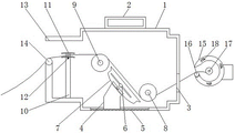
FIG. 1 is a schematic overall front sectional view of the present invention;
FIG. 2 is a schematic structural view of a top-down section of the present invention;
FIG. 3 is a schematic side sectional view of the present invention;
FIG. 4 is a schematic side view of the surface structure of the present invention;
fig. 5 is a schematic view of the front view surface structure of the present invention.
In the figure: 1. a box body; 2. a first fixing plate; 3. a discharge port; 4. a ventilation barrel; 5. filtering with a screen; 6. a fan; 7. a dust collection tray; 8. a first drive shaft; 9. a second drive shaft; 10. a support bar; 11. a pressure plate; 12. a spring; 13. a feed inlet; 14. a first roll axis; 15. a material receiving pipe; 16. a second roll axis; 17. a winding shaft; 18. a card slot; 19. a fixed cover; 20. a side cover; 21. a load-bearing arm; 22. a driver.
Detailed Description
The technical solutions in the embodiments of the present invention will be described clearly and completely with reference to the accompanying drawings in the embodiments of the present invention, and it is obvious that the described embodiments are only some embodiments of the present invention, not all embodiments. Based on the embodiments in the present invention, all other embodiments obtained by a person skilled in the art without creative work belong to the protection scope of the present invention.
Referring to fig. 1-5, the present invention provides a technical solution: a cloth hanging and winding device with a dust removing function for textile production comprises a box body 1, a first fixing plate 2, a discharge port 3, a ventilation barrel 4, a filter screen 5, a fan 6, a dust collection disc 7, a first transmission shaft 8, a second transmission shaft 9, a support rod 10, a pressure plate 11, a spring 12, a feed port 13, a first rolling shaft 14, a material receiving pipe 15, a second rolling shaft 16, a winding shaft 17, a clamping groove 18, a fixing cover 19, a side cover 20, a bearing arm 21 and a driving machine 22, wherein the first fixing plate 2 is arranged on the upper surface of the box body 1, the discharge port 3 is arranged at the bottom end of the side surface of the box body 1, the ventilation barrel 4 is arranged at the bottom end inside the box body 1, the filter screen 5 is arranged below the ventilation barrel 4, the fan 6 is arranged above the ventilation barrel 4, the dust collection disc 7 is arranged on the outer side of the fan 6, the first transmission shaft 8 is arranged inside the box body 1, the second transmission, the inside of case body 1 is equipped with bracing piece 10, and the top of bracing piece 10 is equipped with pressure plate 11, and the inside spring 12 that is equipped with in top of bracing piece 10, and feed inlet 13 has been seted up to one side of case body 1, and the lower extreme of feed inlet 13 is equipped with first roll axle 14, and the side-mounting of case body 1 receives material pipe 15, and receives the surface of material pipe 15 and be equipped with second roll axle 16, receives the inside of material pipe 15 and be equipped with rolling axle 17, and receive the side of material pipe 15 and be connected with fixed cover 19, the side surface of fixed cover 19 is equipped with draw-in groove 18, receive material pipe 15 and be connected with case body 1 through bearing arm 21, and receive one side of material pipe 15 and install driving machine 22, driving machine 22 is connected with rolling axle 17, side cap 20.
The bottom of case body 1 is equipped with the cavity structure, and the filter screen 5 is installed to the bottom of case body 1, and the air current can be through the filter screen 5 of case body 1 bottom outwards outflow, and filter screen 5 can cross off partial dust, avoids the outer air of device to receive the influence.
The surface of pressure plate 11 is the arc, and the below of pressure plate 11 is connected with spring 12, and the curved surface of pressure plate 11 can reduce the wearing and tearing to the cloth surface when the cloth passes through, and the spring 12 of connecting in the below of pressure plate 11 can carry out the fixed tensioning of certain degree with the cloth that passes through in the pressure plate 11, prevents that the cloth from excessively relaxing at the in-process of conveying and leading to the cloth rolling to accomplish the back cloth surface and taking place the fold.
The first rolling shaft 14 and the second rolling shaft 16 are respectively installed at the inlets of the feeding port 13 and the material receiving pipe 15, the feeding port 13 and the material receiving pipe 15 are respectively in rotating connection with the box body 1 and the material receiving pipe 15, the friction on the surface of the cloth can be reduced when the cloth passes through the first rolling shaft 14 and the second rolling shaft 16, and the damage to the surface of the cloth in the winding process is reduced.
The material receiving pipe 15 and the fixed cover 19 form clamping connection, the fixed cover 19 is connected with the winding shaft 17 in an embedded mode through the clamping groove 18, the fixed cover 19 can be moved out from the side face of the material receiving pipe 15, the interior of the material receiving pipe 15 is exposed, an operator can conveniently operate the interior, and the clamping groove 18 which is evenly distributed in the annular mode enables the fixed cover 19 to be attached to the side face of the material receiving pipe 15 more firmly.
The working principle is as follows: when the cloth hanging and winding device with the dust removal function for textile production is used, the whole device is well installed, connected and placed or hung at a proper position through the first fixing plate 2 and the bearing arm 21;
the side cover 20 is pulled upwards to enable the side cover 20 to rotate upwards to expose the inner space of the box body 1, the fixed cover 19 is rotated leftwards to leave the clamping groove 18 and be taken down from the side surface of the material receiving pipe 15, the inner space of the material receiving pipe 15 is exposed, one end of the cloth to be rolled is sequentially placed on the outer surfaces of the second transmission shaft 9, the first transmission shaft 8 and the rolling shaft 17 in the box body 1 through the material inlet 13, the material outlet 3 and the material receiving pipe 15, then the side cover 20 and the fixed cover 19 are reset, after an external power supply is connected to the device, the driving machine 22 is opened, the driving machine 22 drives the rolling shaft 17 to start rolling operation, the rolling shaft 17 rotates to roll the cloth into the material receiving pipe 15, the second transmission shaft 9 and the first transmission shaft 8 play a role in transmission, and the rotating structure of the first rolling shaft 14 and the second rolling shaft 16 reduces friction generated on the first rolling shaft 14 and the second rolling shaft 16 due to cloth transmission, the pressure plate 11 of connecting above the bracing piece 10 increases the friction of certain degree to the cloth of process through the flexible of spring 12, make the cloth level and smooth and tight slightly in the transmission process, avoid the cloth because the unevenness of rolling in-process leads to the rolling back cloth surface to produce the fold, the inside fan 6 of case body 1 can be with the dust suction through its scope cloth, through dust absorption dish 7 get into ventilation barrel 4, at last through filter screen 5 outside discharge, filter screen 5 filters the part dust in the air current, holistic practicality has been increased.
Although embodiments of the present invention have been shown and described, it will be appreciated by those skilled in the art that changes, modifications, substitutions and alterations can be made in these embodiments without departing from the principles and spirit of the invention, the scope of which is defined in the appended claims and their equivalents.
Claims (6)
1. The utility model provides a coiling mechanism is hung with cloth to textile production with dust removal function, includes case body (1) and receipts material pipe (15), its characterized in that: the box is characterized in that a first fixing plate (2) is mounted on the upper surface of the box body (1), a discharge hole (3) is formed in the bottom end of the side surface of the box body (1), an air ventilation barrel (4) is arranged at the bottom end of the inside of the box body (1), a filter screen (5) is arranged below the air ventilation barrel (4), a fan (6) is arranged above the air ventilation barrel (4), a dust collection disc (7) is arranged on the outer side of the fan (6), a first transmission shaft (8) is arranged inside the box body (1), a second transmission shaft (9) is arranged above the side of the first transmission shaft (8), a support rod (10) is arranged inside the box body (1), a pressure plate (11) is arranged at the top end of the support rod (10), a spring (12) is arranged inside the top end of the support rod (10), a feed inlet (13) is formed in one side of the box body (1), and a first rolling shaft (14, receive material pipe (15) are installed to the side of case body (1), and the surface of receiving material pipe (15) is equipped with second roll axle (16), the inside of receiving material pipe (15) is equipped with rolling axle (17), and receives the side of material pipe (15) and be connected with fixed lid (19), the side surface of fixed lid (19) is equipped with draw-in groove (18), receive material pipe (15) and be connected through bearing arm (21) and case body (1), and receive one side of material pipe (15) and install driver (22), driver (22) are connected with rolling axle (17), side cap (20) are installed to the side surface of case body (1).
2. The cloth hanging and winding device with the dust removal function for textile production, as claimed in claim 1, is characterized in that: the bottom of case body (1) is equipped with cavity structure, and filter screen (5) are installed to the bottom of case body (1).
3. The cloth hanging and winding device with the dust removal function for textile production, as claimed in claim 1, is characterized in that: the outer surface of the pressure plate (11) is arc-shaped, and a spring (12) is connected below the pressure plate (11).
4. The cloth hanging and winding device with the dust removal function for textile production, as claimed in claim 1, is characterized in that: the inlet of the feeding port (13) and the receiving pipe (15) is respectively provided with a first rolling shaft (14) and a second rolling shaft (16), and the feeding port (13) and the receiving pipe (15) are respectively in rotating connection with the box body (1) and the receiving pipe (15).
5. The cloth hanging and winding device with the dust removal function for textile production, as claimed in claim 1, is characterized in that: the material receiving pipe (15) and the fixed cover (19) form clamping connection, and the fixed cover (19) is connected with the winding shaft (17) in a nested mode through the clamping groove (18).
6. The cloth hanging and winding device with the dust removal function for textile production, as claimed in claim 1, is characterized in that: the side cover (20) is of a net structure, and the side cover (20) and the box body (1) form rotary connection.
Priority Applications (1)
| Application Number | Priority Date | Filing Date | Title |
|---|---|---|---|
| CN202021068774.5U CN212923717U (en) | 2020-06-11 | 2020-06-11 | Cloth hangs coiling mechanism for textile production with dust removal function |
Applications Claiming Priority (1)
| Application Number | Priority Date | Filing Date | Title |
|---|---|---|---|
| CN202021068774.5U CN212923717U (en) | 2020-06-11 | 2020-06-11 | Cloth hangs coiling mechanism for textile production with dust removal function |
Publications (1)
| Publication Number | Publication Date |
|---|---|
| CN212923717U true CN212923717U (en) | 2021-04-09 |
Family
ID=75322473
Family Applications (1)
| Application Number | Title | Priority Date | Filing Date |
|---|---|---|---|
| CN202021068774.5U Expired - Fee Related CN212923717U (en) | 2020-06-11 | 2020-06-11 | Cloth hangs coiling mechanism for textile production with dust removal function |
Country Status (1)
| Country | Link |
|---|---|
| CN (1) | CN212923717U (en) |
Cited By (1)
| Publication number | Priority date | Publication date | Assignee | Title |
|---|---|---|---|---|
| CN113697580A (en) * | 2021-09-03 | 2021-11-26 | 江苏硕鸿新材料有限公司 | Advertisement cloth coiling mechanism |
-
2020
- 2020-06-11 CN CN202021068774.5U patent/CN212923717U/en not_active Expired - Fee Related
Cited By (2)
| Publication number | Priority date | Publication date | Assignee | Title |
|---|---|---|---|---|
| CN113697580A (en) * | 2021-09-03 | 2021-11-26 | 江苏硕鸿新材料有限公司 | Advertisement cloth coiling mechanism |
| CN113697580B (en) * | 2021-09-03 | 2023-07-07 | 江苏硕鸿新材料有限公司 | Advertisement cloth winding device |
Similar Documents
| Publication | Publication Date | Title |
|---|---|---|
| CN212923717U (en) | Cloth hangs coiling mechanism for textile production with dust removal function | |
| CN115744425A (en) | Automatic draw non-woven fabrics bead cutter of preventing tangent plane fold | |
| CN210561194U (en) | Weaving equipment with clean stoving function | |
| CN213173071U (en) | Wool removing machine convenient for collecting waste materials for textile production | |
| CN211870934U (en) | Weaving is with weaving cloth conveyer | |
| CN218989693U (en) | Blowing and sucking cleaning mechanism of loom | |
| CN112647268A (en) | Textile fabric dust collector | |
| CN215137852U (en) | Weaving machine weaving dirt collection device | |
| CN113388930B (en) | High-precision wool spinning frame roller | |
| CN209243271U (en) | A kind of tailstock concentration cotton receiving fire alarm pretreatment unit | |
| CN210066024U (en) | Dust collector of weaving machine | |
| CN214401044U (en) | Grey cloth wrinkle removing device with good leveling effect | |
| CN216548789U (en) | Automatic plastic film winding roller | |
| CN220977422U (en) | High-speed grain equipment that shakes of surface fabric | |
| CN214054862U (en) | Grind weaving and use roller automatic feeding device | |
| CN212550950U (en) | Dust collecting device of textile machine | |
| CN213061162U (en) | Twisting frame is used in embryo cloth processing | |
| CN115845512B (en) | Dust filtering device of textile machine | |
| CN211394735U (en) | Dust removal structure for carding machine | |
| CN214513451U (en) | Cotton dust processing device of spinning workshop | |
| CN215163987U (en) | Uniform-speed feeding device for jig dyeing machine for spinning | |
| CN210357959U (en) | Dust control device of cylindrical mushroom screening machine | |
| CN215087581U (en) | Production auto sucking machine for acoustic material | |
| CN219879422U (en) | Cloth bag dust collector is used in grinding apparatus processing | |
| CN220788997U (en) | Be used for knitting dust collector for cloth processing |
Legal Events
| Date | Code | Title | Description |
|---|---|---|---|
| GR01 | Patent grant | ||
| GR01 | Patent grant | ||
| CF01 | Termination of patent right due to non-payment of annual fee | ||
| CF01 | Termination of patent right due to non-payment of annual fee |
Granted publication date: 20210409 |