CN218989693U - Blowing and sucking cleaning mechanism of loom - Google Patents
Blowing and sucking cleaning mechanism of loom Download PDFInfo
- Publication number
- CN218989693U CN218989693U CN202320056250.1U CN202320056250U CN218989693U CN 218989693 U CN218989693 U CN 218989693U CN 202320056250 U CN202320056250 U CN 202320056250U CN 218989693 U CN218989693 U CN 218989693U
- Authority
- CN
- China
- Prior art keywords
- blowing
- dust
- loom
- frame
- fixedly connected
- Prior art date
- Legal status (The legal status is an assumption and is not a legal conclusion. Google has not performed a legal analysis and makes no representation as to the accuracy of the status listed.)
- Active
Links
- 238000007664 blowing Methods 0.000 title claims abstract description 99
- 230000007246 mechanism Effects 0.000 title claims abstract description 65
- 238000004140 cleaning Methods 0.000 title claims abstract description 24
- 239000000428 dust Substances 0.000 claims abstract description 126
- 239000004744 fabric Substances 0.000 claims abstract description 28
- 238000001914 filtration Methods 0.000 claims abstract description 25
- 238000007599 discharging Methods 0.000 claims description 4
- 238000009423 ventilation Methods 0.000 claims description 3
- 239000002245 particle Substances 0.000 abstract description 5
- 238000000034 method Methods 0.000 abstract description 2
- 238000010521 absorption reaction Methods 0.000 description 11
- 238000010586 diagram Methods 0.000 description 4
- 238000004804 winding Methods 0.000 description 4
- 238000004891 communication Methods 0.000 description 3
- 239000000463 material Substances 0.000 description 3
- 238000000605 extraction Methods 0.000 description 2
- 230000002035 prolonged effect Effects 0.000 description 2
- 238000005096 rolling process Methods 0.000 description 2
- 238000006467 substitution reaction Methods 0.000 description 2
- 229920000742 Cotton Polymers 0.000 description 1
- 238000005520 cutting process Methods 0.000 description 1
- 230000007547 defect Effects 0.000 description 1
- 230000017525 heat dissipation Effects 0.000 description 1
- 238000009987 spinning Methods 0.000 description 1
- 239000012780 transparent material Substances 0.000 description 1
- 238000009941 weaving Methods 0.000 description 1
Images





Landscapes
- Auxiliary Weaving Apparatuses, Weavers' Tools, And Shuttles (AREA)
Abstract
The utility model belongs to the field of cleaning mechanisms, in particular to a blowing and sucking cleaning mechanism of a loom, which aims at the problems that in the existing use process of the loom, tiny dust particles can appear, the dust can adhere to the surfaces of yarns and fabrics and affect the surface quality of the fabrics; the dust on the cloth can be blown off through the blowing mechanism, the dust in the air can be effectively filtered through the filtering mechanism, the dust in the air can be intercepted, the air containing the dust can be discharged through the dust collecting mechanism, and the heat of the servo motor can be dissipated.
Description
Technical Field
The utility model relates to the technical field of cleaning mechanisms, in particular to a blowing and sucking cleaning mechanism of a loom.
Background
Loom, which is used for weaving cloth, also called spinning machine, loom, cotton loom, etc., is driven by manpower. The utility model of random society, full-automatic loom is widely used.
Through retrieval, the publication number CN209481921U discloses a loom, which comprises a frame and a winding shaft for winding cloth, wherein a cross rod is arranged on the frame, a sliding frame is assembled on the cross rod, a fixed frame is arranged on the sliding frame, a cutter is fixed on the fixed frame through a fixed assembly, the cutting edge of the cutter is vertical to the cross rod, and a driving mechanism for driving the sliding frame to move back and forth along the length direction of the cross rod is arranged on the frame; the rack is provided with a mounting seat for mounting the winding shaft, the mounting seat is arranged below the cross rod, and a driving piece for driving the winding shaft to rotate is arranged in the rack. The following problems exist in the technical scheme:
during the use of the loom, some tiny dust particles can appear, and the dust can adhere to the surfaces of the yarns and the loom, so that the dust particles can be mixed in the rolled cloth, and the surface quality of the cloth is affected;
in order to solve the problems, the utility model provides a blowing and sucking cleaning mechanism of a loom.
Disclosure of Invention
The utility model provides a blowing and sucking cleaning mechanism of a loom, which solves the defects that in the prior art, tiny dust particles can appear in the using process of the loom, and the dust can adhere to the surfaces of yarns and the loom, so that dust particles can be mixed in the rolled cloth, and the surface quality of the cloth is affected.
The utility model provides the following technical scheme:
the blowing and sucking cleaning mechanism of the loom comprises a loom main body, wherein the loom main body comprises a loom body, a dust hood, a blowing hood and a servo motor, a rotary door is arranged on the front side of the loom body, two square plates are fixedly connected to one side of the loom body, two rotating rods are fixedly connected to two sides of the rotary door, and one ends of the two rotating rods are respectively connected with one side, close to the two square plates, in a rotating way;
the blowing mechanism is arranged in the blowing cover and is used for blowing dust to the fabric on the roller;
the dust collection mechanism is arranged in the dust collection cover and used for discharging dust blown down;
the filtering mechanism is arranged in the dust hood and used for filtering dust.
In one possible design, the blowing mechanism comprises a blower for blowing, the blower is embedded on the inner wall of the blowing cover, a vent is formed in one side of the blowing cover, and a blowing port is formed in one side of the machine body.
In a possible design, dust absorption mechanism is including exhaust fan, connecting pipe and hollow frame, the outside of exhaust fan is embedded on the inner wall of suction hood, the dust absorption hole has been seted up to one side of organism, one side of hollow frame and the inner wall fixed connection of organism, a plurality of dust absorption mouths have been seted up to one side of hollow frame, one end of connecting pipe and one side inner wall fixed connection of organism, the other end and the top fixed connection of hollow frame of connecting pipe, the bottom one side fixedly connected with hollow plate that is used for airing exhaust of suction hood.
In one possible design, the filtering mechanism comprises a frame body, a filter screen and a handle which is convenient for the frame body to pull out, an opening is formed in the top of the dust hood, two sides of the frame body are respectively connected with two side inner walls of the dust hood in a sliding mode, the filter screen is embedded in one side of the frame body, the bottom of the handle is fixedly connected with the top of the frame body, and the filter screen is made of a HEPA filter screen.
In one possible design, the top fixedly connected with short board of suction hood, one side threaded connection of short board has the screw rod, the top sliding connection of suction hood has the movable plate, the one end of screw rod rotates with one side of movable plate to be connected, the top fixedly connected with frame of suction hood, the movable plate is pegged graft in the space that the frame formed.
In one possible design, the two sides of the frame body are fixedly connected with sliding strips, the inner walls of the two sides of the dust hood are provided with sliding grooves, and one side of each sliding strip is in sliding connection with the inner wall of each sliding groove.
It is to be understood that both the foregoing general description and the following detailed description are exemplary and explanatory only and are not restrictive of the utility model as claimed.
In the utility model, as the blower is arranged, the blowing force is generated when the blower is started, blown wind enters the space formed by the machine body and the revolving door through the blowing opening, and the blowing blows dust to the cloth being wound, so that dust on the surface is separated from the cloth, and the dust on the cloth can be blown off;
according to the utility model, as the exhaust fan, the connecting pipe and the hollow frame are arranged, suction force is generated when the exhaust fan is started, blown dust and wind blown out by the blower enter the hollow frame through the dust collection openings on the hollow frame, then the air is conveyed into the dust collection cover through the connecting pipe for filtering, the filtered wind can be discharged through the exhaust fan, so that the wind containing the dust can be discharged, and finally the filtered wind can be blown onto the servo motor through the hollow plate, so that the heat of the servo motor can be dissipated, and the service life of the servo motor is prolonged;
according to the utility model, the filter screen is arranged, and is made of HEPA (high efficiency particulate air) filter screen, so that dust in air can be effectively filtered by the filter screen, dust in blowing air can be intercepted, and discharge is avoided;
the dust collecting device is reasonable in structure, dust on cloth can be blown off through the blowing mechanism, dust in air can be effectively filtered through the filtering mechanism, dust in blowing can be intercepted, blowing containing dust can be discharged through the dust collecting mechanism, the filtering mechanism can conveniently filter the dust in blowing, and heat can be dissipated to the servo motor.
Drawings
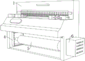
Fig. 1 is a schematic front view of a blowing and sucking cleaning mechanism of a loom according to an embodiment of the present utility model;
fig. 2 is a schematic diagram of the internal structure of a blowing and sucking cleaning mechanism of a loom according to an embodiment of the present utility model;
fig. 3 is a schematic diagram of an internal structure of a blowing hood of a blowing and sucking cleaning mechanism of a loom according to an embodiment of the present utility model;
FIG. 4 is a schematic view of a hollow frame and a connecting pipe of a blowing and sucking cleaning mechanism of a loom according to an embodiment of the present utility model;
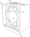
fig. 5 is a schematic diagram of the internal structure of a dust hood of a blowing and sucking cleaning mechanism of a loom according to an embodiment of the present utility model;
FIG. 6 is a schematic view of a screw, a short plate and a frame structure of a blowing and sucking cleaning mechanism of a loom according to an embodiment of the present utility model;
fig. 7 is a schematic diagram of a filtering mechanism of a blowing and sucking cleaning mechanism of a loom according to an embodiment of the present utility model.
Reference numerals:
1. a body; 2. a dust hood; 3. a revolving door; 4. a hollow frame; 5. a roller; 6. a blowing hood; 7. a blower; 8. an exhaust fan; 9. a hollow slab; 10. a short plate; 11. a filter screen; 12. a screw; 13. a moving plate; 14. a frame; 15. a slide bar; 16. a frame; 17. a connecting pipe; 18. and (5) square plates.
Detailed Description
Embodiments of the present utility model will be described below with reference to the accompanying drawings in the embodiments of the present utility model.
In describing embodiments of the present utility model, it should be noted that, unless explicitly stated and limited otherwise, the terms "coupled" and "mounted" should be interpreted broadly, and for example, "coupled" may or may not be detachably coupled; may be directly connected or indirectly connected through an intermediate medium. In addition, "communication" may be direct communication or may be indirect communication through an intermediary. Wherein, "fixed" means that the relative positional relationship is not changed after being connected to each other. References to orientation terms, such as "inner", "outer", "top", "bottom", etc., in the embodiments of the present utility model are merely to refer to the orientation of the drawings and, therefore, the use of orientation terms is intended to better and more clearly illustrate and understand the embodiments of the present utility model, rather than to indicate or imply that the devices or elements referred to must have a particular orientation, be constructed and operated in a particular orientation, and are therefore not to be construed as limiting the embodiments of the present utility model.
In embodiments of the present utility model, the terms "first," "second," and the like are used for descriptive purposes only and are not to be construed as indicating or implying relative importance or implicitly indicating the number of technical features indicated. Thus, a feature defining "a first" or "a second" may explicitly or implicitly include one or more such feature.
In the embodiment of the present utility model, "and/or" is merely an association relationship describing an association object, and indicates that three relationships may exist, for example, a and/or B may indicate: a exists alone, A and B exist together, and B exists alone. In addition, the character "/" herein generally indicates that the front and rear associated objects are an "or" relationship.
Reference in the specification to "one embodiment" or "some embodiments" or the like means that a particular feature, structure, or characteristic described in connection with the embodiment is included in one or more embodiments of the utility model. Thus, appearances of the phrases "in one embodiment," "in some embodiments," "in other embodiments," and the like in the specification are not necessarily all referring to the same embodiment, but mean "one or more but not all embodiments" unless expressly specified otherwise. The terms "comprising," "including," "having," and variations thereof mean "including but not limited to," unless expressly specified otherwise.
Example 1
Referring to fig. 1-7, a blowing and sucking cleaning mechanism of a loom comprises a loom main body, wherein the loom main body comprises a loom body 1, a dust hood 2, a blowing hood 6 and a servo motor, a rotary door 3 is arranged at the front side of the loom body 1, two square plates 18 are fixedly connected to one side of the loom body 1, two rotating rods are fixedly connected to two sides of the rotary door 3, and one ends of the two rotating rods are respectively connected with one side, close to the two square plates 18, in a rotating way;
the blowing mechanism is arranged in the blowing cover 6 and is used for blowing dust to the fabric on the roller 5;
the dust collection mechanism is arranged in the dust collection cover 2 and is used for discharging dust blown down;
and the filtering mechanism is arranged in the dust hood 2 and is used for filtering dust.
Above-mentioned technical scheme can blow down the last dust of cloth through blowing mechanism, can filter the dust in the air effectually through filtering mechanism, intercepts the dust in blowing, can discharge the blowing that contains the dust through dust extraction mechanism, and the filtering mechanism of being convenient for filters the dust in blowing, can also dispel the heat to servo motor.
Referring to fig. 2 and 3, the blowing mechanism includes a blower 7 for blowing, the blower 7 is embedded on the inner wall of the blowing hood 6, a ventilation opening is formed on one side of the blowing hood 6, and a blowing opening is formed on one side of the machine body 1.
Above-mentioned technical scheme hair-dryer 7 start can produce blowing force, and the wind of blowing out can get into in the space that organism 1 and revolving door 3 formed through the mouth of blowing, and the blowing can blow ash to the cloth that is rolling, makes the dust on surface break away from the cloth to can blow off the last dust of cloth.
Referring to fig. 1, 4 and 5, the dust absorption mechanism is including exhaust fan 8, connecting pipe 17 and hollow frame 4, and the outside of exhaust fan 8 is embedded on the inner wall of suction hood 2, and the dust absorption hole has been seted up to one side of organism 1, and the inner wall fixed connection of one side and organism 1 of hollow frame 4, and a plurality of dust absorption mouths have been seted up to one side of hollow frame 4, and one end of connecting pipe 17 and one side inner wall fixed connection of organism 1, the top fixed connection of the other end and hollow frame 4 of connecting pipe 17, the bottom one side fixedly connected with of suction hood 2 is used for the hollow board 9 of airing exhaust.
Above-mentioned technical scheme exhaust fan 8's start can produce the suction, and the dust of blowing off and the wind that blower 7 blown out can get into in the hollow frame 4 through the dust absorption mouth that crosses on the hollow frame 4, carry in the suction hood 2 through connecting pipe 17 later and filter, and the blowing after the filtration can be discharged through exhaust fan 8 to can discharge the blowing that contains the dust, blow after the filtration can blow to servo motor through hollow plate 9 on, can dispel the heat to servo motor like this, extension servo motor's life.
Referring to fig. 1, 5 and 7, the filtering mechanism comprises a frame 16, a filter screen 11 and a handle which is convenient for the frame 16 to pull out, the top of the dust hood 2 is provided with an opening, two sides of the frame 16 are respectively in sliding connection with two side inner walls of the dust hood 2, the filter screen 11 is embedded at one side of the frame 16, the bottom of the handle is fixedly connected with the top of the frame 16, and the filter screen 11 is made of a HEPA filter screen.
Above-mentioned technical scheme filter screen 11's material is the HEPA filter screen, and this filter screen can be effectual filters the dust in the air, intercepts the dust in the blowing, avoids the discharge.
Example 2
Referring to fig. 1-7, a blowing and sucking cleaning mechanism of a loom comprises a loom main body, wherein the loom main body comprises a loom body 1, a dust hood 2, a blowing hood 6 and a servo motor, a rotary door 3 is arranged at the front side of the loom body 1, two square plates 18 are fixedly connected to one side of the loom body 1, two rotating rods are fixedly connected to two sides of the rotary door 3, and one ends of the two rotating rods are respectively connected with one side, close to the two square plates 18, in a rotating way;
the blowing mechanism is arranged in the blowing cover 6 and is used for blowing dust to the fabric on the roller 5;
the dust collection mechanism is arranged in the dust collection cover 2 and is used for discharging dust blown down;
and the filtering mechanism is arranged in the dust hood 2 and is used for filtering dust.
Above-mentioned technical scheme can blow down the last dust of cloth through blowing mechanism, can filter the dust in the air effectually through filtering mechanism, intercepts the dust in blowing, can discharge the blowing that contains the dust through dust extraction mechanism, and the filtering mechanism of being convenient for filters the dust in blowing, can also dispel the heat to servo motor.
Referring to fig. 2 and 3, the blowing mechanism includes a blower 7 for blowing, the blower 7 is embedded on the inner wall of the blowing hood 6, a ventilation opening is formed on one side of the blowing hood 6, and a blowing opening is formed on one side of the machine body 1.
Above-mentioned technical scheme hair-dryer 7 start can produce blowing force, and the wind of blowing out can get into in the space that organism 1 and revolving door 3 formed through the mouth of blowing, and the blowing can blow ash to the cloth that is rolling, makes the dust on surface break away from the cloth to can blow off the last dust of cloth.
Referring to fig. 1, 4 and 5, the dust absorption mechanism is including exhaust fan 8, connecting pipe 17 and hollow frame 4, and the outside of exhaust fan 8 is embedded on the inner wall of suction hood 2, and the dust absorption hole has been seted up to one side of organism 1, and the inner wall fixed connection of one side and organism 1 of hollow frame 4, and a plurality of dust absorption mouths have been seted up to one side of hollow frame 4, and one end of connecting pipe 17 and one side inner wall fixed connection of organism 1, the top fixed connection of the other end and hollow frame 4 of connecting pipe 17, the bottom one side fixedly connected with of suction hood 2 is used for the hollow board 9 of airing exhaust.
Above-mentioned technical scheme exhaust fan 8's start can produce the suction, and the dust of blowing off and the wind that blower 7 blown out can get into in the hollow frame 4 through the dust absorption mouth that crosses on the hollow frame 4, carry in the suction hood 2 through connecting pipe 17 later and filter, and the blowing after the filtration can be discharged through exhaust fan 8 to can discharge the blowing that contains the dust, blow after the filtration can blow to servo motor through hollow plate 9 on, can dispel the heat to servo motor like this, extension servo motor's life.
Referring to fig. 1, 5 and 7, the filtering mechanism comprises a frame 16, a filter screen 11 and a handle which is convenient for the frame 16 to pull out, the top of the dust hood 2 is provided with an opening, two sides of the frame 16 are respectively in sliding connection with two side inner walls of the dust hood 2, the filter screen 11 is embedded at one side of the frame 16, the bottom of the handle is fixedly connected with the top of the frame 16, and the filter screen 11 is made of a HEPA filter screen.
Above-mentioned technical scheme filter screen 11's material is the HEPA filter screen, and this filter screen can be effectual filters the dust in the air, intercepts the dust in the blowing, avoids the discharge.
Referring to fig. 5 and 6, a short plate 10 is fixedly connected to the top of the dust hood 2, a screw 12 is screwed on one side of the short plate 10, a moving plate 13 is slidingly connected to the top of the dust hood 2, one end of the screw 12 is rotatably connected with one side of the moving plate 13, a frame 14 is fixedly connected to the top of the dust hood 2, and the moving plate 13 is inserted into a space formed by the frame 14.
The rotation of the screw 12 in the above technical scheme drives the transverse movement of the moving plate 13, so that one end of the moving plate 13 is inserted into the space formed by the frame 14, thereby fixing the frame 16 and avoiding being pulled out by unrelated personnel at will.
Referring to fig. 5 and 7, the two sides of the frame 16 are fixedly connected with sliding strips 15, the inner walls of the two sides of the dust hood 2 are provided with sliding grooves, and one side of each sliding strip 15 is in sliding connection with the inner wall of each sliding groove.
According to the technical scheme, the sliding grooves and the sliding strips 15 enable the frame 16 to reduce friction force during movement, so that movement is smoother.
The working principle and the using flow of the technical scheme are as follows: when the loom main body starts to be used, firstly, the rotary door 3 is closed, the rotary door 3 is made of transparent materials, the internal condition can be seen, the roller 5 starts to rotate to wind the loom, as the blower 7 is arranged, blowing force can be generated when the blower 7 is started, blown wind can enter the space formed by the loom body 1 and the rotary door 3 through the blowing opening, blowing can blow ash on the cloth being wound, dust on the surface is separated from the cloth, so that the dust on the cloth can be blown off, when the blower is blown, suction force can be generated when the exhaust fan 8 is started, the blown dust and the wind blown out by the blower 7 can enter the hollow frame 4 through the dust collection opening on the hollow frame 4, then the wind is conveyed into the dust collection cover 2 through the connecting pipe 17, when the wind passes through the filter screen 11, the dust in the air can be effectively filtered due to the HEPA filter screen made of the material of the filter screen 11, the dust in the air blowing is intercepted, the filtered air blowing can be discharged through the exhaust fan 8, so that the air blowing containing the dust can be discharged, finally, the filtered air blowing can be blown to the servo motor through the hollow plate 9, so that the heat dissipation of the servo motor can be realized, the service life of the servo motor is prolonged, when the filter screen 11 needs to be replaced, the screw rod 12 is rotated outwards, the rotation of the screw rod 12 drives the transverse movement of the moving plate 13, the moving plate 13 leaves the frame 14 and leaves the top of the frame 16, then the handle is held, the frame 16 is pulled upwards, the frame 16 leaves the dust hood 2, the filter screen 11 on the frame 16 is removed, a new filter screen 11 is replaced, the filter screen 11 can be replaced, the frame 16 is inserted into the dust hood 2 after the replacement, the screw rod 12 is rotated inwards, the rotation of the screw 12 drives the movable plate 13 to move transversely, so that one end of the movable plate 13 is inserted into the space formed by the frame 14, thereby fixing the frame 16 and avoiding being pulled out by irrelevant personnel at will.
The present utility model is not limited to the above embodiments, and any person skilled in the art can easily think about the changes or substitutions within the technical scope of the present utility model, and the changes or substitutions are intended to be covered by the scope of the present utility model; embodiments of the utility model and features of the embodiments may be combined with each other without conflict. Therefore, the protection scope of the utility model is subject to the protection scope of the claims.
Claims (6)
1. A blowing and sucking cleaning mechanism of a loom, comprising:
the loom comprises a loom body, wherein the loom body comprises an organism (1), a dust hood (2), a blowing hood (6) and a servo motor, a rotary door (3) is arranged at the front side of the organism (1), two square plates (18) are fixedly connected to one side of the organism (1), two rotating rods are fixedly connected to two sides of the rotary door (3), and one ends of the two rotating rods are respectively connected with one side, close to the two square plates (18), in a rotating way;
the blowing mechanism is arranged in the blowing cover (6) and is used for blowing dust to the fabric on the roller (5);
the dust collection mechanism is arranged in the dust collection cover (2) and is used for discharging dust blown down;
and the filtering mechanism is arranged in the dust hood (2) and is used for filtering dust.
2. The blowing and sucking cleaning mechanism of a loom according to claim 1, wherein the blowing mechanism comprises a blower (7) for blowing, the blower (7) is embedded on the inner wall of a blowing cover (6), a ventilation opening is formed in one side of the blowing cover (6), and a blowing opening is formed in one side of the loom body (1).
3. The blowing and sucking cleaning mechanism of a loom according to claim 1, characterized in that the dust sucking mechanism comprises an exhaust fan (8), a connecting pipe (17) and a hollow frame (4), wherein the outer side of the exhaust fan (8) is embedded on the inner wall of a dust hood (2), a dust sucking hole is formed in one side of the machine body (1), one side of the hollow frame (4) is fixedly connected with the inner wall of the machine body (1), a plurality of dust sucking holes are formed in one side of the hollow frame (4), one end of the connecting pipe (17) is fixedly connected with the inner wall of one side of the machine body (1), the other end of the connecting pipe (17) is fixedly connected with the top of the hollow frame (4), and a hollow plate (9) for exhausting air is fixedly connected to one side of the bottom of the dust hood (2).
4. A blowing-sucking cleaning mechanism of a loom according to any one of claims 1-3, wherein the filtering mechanism comprises a frame body (16), a filter screen (11) and a handle which is convenient for the frame body (16) to be pulled out, an opening is formed in the top of the dust hood (2), two sides of the frame body (16) are respectively in sliding connection with two side inner walls of the dust hood (2), the filter screen (11) is embedded in one side of the frame body (16), the bottom of the handle is fixedly connected with the top of the frame body (16), and the filter screen (11) is made of a HEPA filter screen.
5. The blowing and sucking cleaning mechanism of a loom according to claim 1, characterized in that a short plate (10) is fixedly connected to the top of the dust hood (2), a screw (12) is connected to one side of the short plate (10) in a threaded manner, a movable plate (13) is slidingly connected to the top of the dust hood (2), one end of the screw (12) is rotatably connected to one side of the movable plate (13), a frame (14) is fixedly connected to the top of the dust hood (2), and the movable plate (13) is inserted into a space formed by the frame (14).
6. The blowing and sucking cleaning mechanism of a loom according to claim 4, wherein two sides of the frame body (16) are fixedly connected with sliding strips (15), sliding grooves are formed in inner walls of two sides of the dust hood (2), and one side of each sliding strip (15) is in sliding connection with the inner wall of each sliding groove.
Priority Applications (1)
| Application Number | Priority Date | Filing Date | Title |
|---|---|---|---|
| CN202320056250.1U CN218989693U (en) | 2023-01-09 | 2023-01-09 | Blowing and sucking cleaning mechanism of loom |
Applications Claiming Priority (1)
| Application Number | Priority Date | Filing Date | Title |
|---|---|---|---|
| CN202320056250.1U CN218989693U (en) | 2023-01-09 | 2023-01-09 | Blowing and sucking cleaning mechanism of loom |
Publications (1)
| Publication Number | Publication Date |
|---|---|
| CN218989693U true CN218989693U (en) | 2023-05-09 |
Family
ID=86219964
Family Applications (1)
| Application Number | Title | Priority Date | Filing Date |
|---|---|---|---|
| CN202320056250.1U Active CN218989693U (en) | 2023-01-09 | 2023-01-09 | Blowing and sucking cleaning mechanism of loom |
Country Status (1)
| Country | Link |
|---|---|
| CN (1) | CN218989693U (en) |
Cited By (1)
| Publication number | Priority date | Publication date | Assignee | Title |
|---|---|---|---|---|
| CN116398123A (en) * | 2023-05-15 | 2023-07-07 | 江苏盖亚环境科技股份有限公司 | High-efficient real-time monitoring system of drilling and testing integrated equipment |
-
2023
- 2023-01-09 CN CN202320056250.1U patent/CN218989693U/en active Active
Cited By (2)
| Publication number | Priority date | Publication date | Assignee | Title |
|---|---|---|---|---|
| CN116398123A (en) * | 2023-05-15 | 2023-07-07 | 江苏盖亚环境科技股份有限公司 | High-efficient real-time monitoring system of drilling and testing integrated equipment |
| CN116398123B (en) * | 2023-05-15 | 2023-12-01 | 江苏盖亚环境科技股份有限公司 | High-efficient real-time monitoring system of drilling and testing integrated equipment |
Similar Documents
| Publication | Publication Date | Title |
|---|---|---|
| CN208810787U (en) | A kind of Weaving device dust-extraction unit | |
| CN212223243U (en) | Loom with dust removal device | |
| CN218436258U (en) | Circulating emission reduction three-roller calender | |
| CN217247531U (en) | Gauze mask apparatus for producing with automatic dust removal function | |
| CN216074133U (en) | Cotton yarn weaving carding equipment | |
| CN214199022U (en) | Air ventilation and filtration device for elevator car | |
| CN220887828U (en) | Roving blowing and sucking type cleaning device | |
| CN211133467U (en) | Prevent subsiding useless hair collection device | |
| CN209636490U (en) | A dust removal device for a printing and dyeing dryer | |
| CN220538029U (en) | Drawing frame with dust removal function | |
| JP4134768B2 (en) | Air conditioner | |
| CN216498102U (en) | Horizontal drum-type shot blasting machine | |
| CN118066637A (en) | FFU fan filtering equipment and using method thereof | |
| CN209243271U (en) | A kind of tailstock concentration cotton receiving fire alarm pretreatment unit | |
| CN211665302U (en) | Yarn dust removal mechanism of large circular knitting machine | |
| CN213919546U (en) | Dust collector for mask production line | |
| CN116427067A (en) | A textile dust collection device for a textile machine | |
| CN224113554U (en) | Air flow device | |
| CN224121361U (en) | A factory ventilation structure | |
| CN219174840U (en) | Non-woven fabric cleaning device | |
| CN223760677U (en) | Textile machine textile dust collecting device for spinning | |
| CN222594124U (en) | A three-roller cotton mixing machine for non-woven fabrics with automatic dust removal | |
| CN218001780U (en) | Adjustable air quantity fan | |
| CN223723328U (en) | Yarn separating device of reeding machine | |
| CN216855991U (en) | Special small-size sack formula dust collecting equipment of industry |
Legal Events
| Date | Code | Title | Description |
|---|---|---|---|
| GR01 | Patent grant | ||
| GR01 | Patent grant |