CN212909002U - GGJ low-voltage reactive power compensation cabinet - Google Patents
GGJ low-voltage reactive power compensation cabinet Download PDFInfo
- Publication number
- CN212909002U CN212909002U CN202021818820.9U CN202021818820U CN212909002U CN 212909002 U CN212909002 U CN 212909002U CN 202021818820 U CN202021818820 U CN 202021818820U CN 212909002 U CN212909002 U CN 212909002U
- Authority
- CN
- China
- Prior art keywords
- cabinet
- compensation
- circuit
- fuse
- cabinet body
- Prior art date
- Legal status (The legal status is an assumption and is not a legal conclusion. Google has not performed a legal analysis and makes no representation as to the accuracy of the status listed.)
- Expired - Fee Related
Links
- 239000003990 capacitor Substances 0.000 claims abstract description 22
- 230000005611 electricity Effects 0.000 claims abstract description 5
- 230000017525 heat dissipation Effects 0.000 claims description 7
- 238000006243 chemical reaction Methods 0.000 claims description 5
- 238000012423 maintenance Methods 0.000 abstract description 4
- 238000001816 cooling Methods 0.000 description 12
- 230000002035 prolonged effect Effects 0.000 description 4
- 230000001939 inductive effect Effects 0.000 description 2
- 238000009434 installation Methods 0.000 description 2
- 230000004048 modification Effects 0.000 description 2
- 238000012986 modification Methods 0.000 description 2
- 230000000739 chaotic effect Effects 0.000 description 1
- 238000010586 diagram Methods 0.000 description 1
Images


Classifications
-
- Y—GENERAL TAGGING OF NEW TECHNOLOGICAL DEVELOPMENTS; GENERAL TAGGING OF CROSS-SECTIONAL TECHNOLOGIES SPANNING OVER SEVERAL SECTIONS OF THE IPC; TECHNICAL SUBJECTS COVERED BY FORMER USPC CROSS-REFERENCE ART COLLECTIONS [XRACs] AND DIGESTS
- Y02—TECHNOLOGIES OR APPLICATIONS FOR MITIGATION OR ADAPTATION AGAINST CLIMATE CHANGE
- Y02E—REDUCTION OF GREENHOUSE GAS [GHG] EMISSIONS, RELATED TO ENERGY GENERATION, TRANSMISSION OR DISTRIBUTION
- Y02E40/00—Technologies for an efficient electrical power generation, transmission or distribution
- Y02E40/30—Reactive power compensation
Landscapes
- Emergency Protection Circuit Devices (AREA)
Abstract
The utility model discloses a GGJ low-voltage reactive power compensation cabinet, which comprises a cabinet body, wherein a capacitor, a fuse, a capacitance switching contactor, a current-limiting reactor, a current transformer and an ammeter are arranged in the cabinet body, isolator and capacitance compensation controller, the fuse, capacitance switching contactor, current limiting reactor and condenser are established ties and are formed compensating circuit, capacitance compensation controller's input and electric wire netting circuit connection, the output is connected to compensating circuit's input, compensating circuit's output is connected to electric wire netting circuit, isolator and current transformer set up between electric wire netting circuit and compensating circuit, the ampere meter is connected with the current transformer electricity, the internal chamber of placing that is provided with of cabinet, the left and right sides of placing the intracavity all is provided with the mounting panel, the condenser, the fuse, capacitance switching contactor and current limiting reactor top-down are installed on the mounting panel of placing the intracavity. The utility model discloses interior electric elements arrange rationally, and the wiring is simple, convenient maintenance.
Description
Technical Field
The utility model relates to an electricity cabinet technical field, in particular to GGJ low pressure reactive compensation cabinet.
Background
The load types in the power system mostly belong to inductive loads, and power electronic equipment is widely used by power utilization enterprises, so that the power factor of a power grid is low. The lower power factor reduces the utilization rate of equipment, increases the power supply investment, damages the voltage quality, reduces the service life of the equipment and greatly increases the line loss. Therefore, the capacitance compensation cabinet is connected in the power system, inductive load can be balanced, power factor is improved, and utilization rate of equipment is improved.
Inside being provided with multiple electric elements of current capacitance compensation cabinet, multiple electric elements's installation overall arrangement is very chaotic, leads to the wiring confusion, increases the staff and carries out the degree of difficulty of overhauing capacitance compensation cabinet, inconvenient staff's operation.
Disclosure of Invention
The to-be-solved technical problem of the utility model is, to the not enough among the above-mentioned prior art, provide a GGJ low pressure reactive compensation cabinet, it enables the electric elements' in the compensation cabinet rationally distributed, and the wiring is simple, reduces the staff and to the maintenance degree of difficulty of compensation cabinet, makes things convenient for the staff to overhaul.
In order to solve the technical problem, the technical scheme of the utility model is that:
a GGJ low-voltage reactive power compensation cabinet comprises a cabinet body, wherein a capacitor, a fuse, a capacitance switching contactor, a current-limiting reactor, a current transformer, an ammeter, an isolating switch and a capacitance compensation controller are arranged in the cabinet body, the fuse, the capacitance switching contactor, the current-limiting reactor and the capacitor are connected in series through a cable to form a compensation circuit, the input end of the capacitance compensation controller is connected with a power grid circuit arranged in the cabinet body, the output end of the capacitance compensation controller is connected to the input end of the compensation circuit, the output end of the compensation circuit is connected to the power grid circuit, the isolating switch and the current transformer are arranged between the power grid circuit and the compensation circuit, one end of the isolating switch is connected with the power grid circuit, the other end of the isolating switch is connected with the input end of the current transformer, the ammeter is electrically connected with the current transformer, a placing cavity is arranged in the cabinet body, mounting plates are arranged on the left side and the right side of the placing cavity, and the capacitor, the fuse, the capacitance switching contactor and the current limiting reactor are mounted on the mounting plates in the placing cavity from top to bottom.
As a preferred scheme, a voltage conversion switch and a voltmeter are further arranged in the cabinet body, and both the voltage conversion switch and the voltmeter are arranged in a power grid circuit.
As a preferred scheme, the cabinet body is also internally provided with an arrester, the arrester is connected with the compensation circuit in parallel, and the arrester is electrically connected with the output end of the current transformer.
As a preferred scheme, the top of the cabinet body is provided with a cooling fan, the cabinet body is internally provided with a temperature controller, one end of the temperature controller is electrically connected with a power grid circuit through a fuse, and the other end of the temperature controller is electrically connected with the cooling fan.
Preferably, the isolating switch is a knife-fuse switch.
Preferably, the capacitor is a power capacitor.
As a preferred scheme, the front end of the cabinet body is provided with an indicator light for indicating the work of the capacitor.
As a preferred scheme, the lower part of the front end of the cabinet body is provided with heat dissipation holes.
The utility model has the advantages that: a placing cavity is arranged in the cabinet body, mounting plates are arranged on the left side and the right side of the placing cavity, and the capacitor, the fuse, the capacitance switching contactor and the current limiting reactor are arranged on the mounting plates in the placing cavity from top to bottom, so that the layout of electrical elements in the compensation cabinet is reasonable, the wiring is simple, the maintenance difficulty of a worker on the compensation cabinet is reduced, and the maintenance of the worker is facilitated; the arrangement of the lightning arrester can enable the compensation cabinet to have the lightning protection function, so that the service life of the compensation cabinet is prolonged more effectively; one end of the temperature controller is electrically connected with the power grid circuit through the fuse, and the other end of the temperature controller is electrically connected with the cooling fan, so that the switch of the cooling fan can be controlled according to the temperature in the cabinet body, and the cabinet is more intelligent, environment-friendly and energy-saving; the setting of louvre can effectively improve the heat dissipation function of compensation cabinet, effectively prolongs the life of compensation cabinet.
Drawings
FIG. 1 is a front view of an embodiment of the present invention;
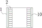
fig. 2 is an interior side view of an embodiment of the invention;
fig. 3 is a schematic view illustrating the installation of the capacitor in the cabinet of the present invention;
fig. 4 is an electrical schematic diagram of the GGJ low-voltage reactive power compensation cabinet of the present invention.
In the figure: 1-cabinet, 2-capacitor, 3-fuse, 4-capacitance switching contactor, 5-current limiting reactor, 6-current transformer, 7-ammeter, 8-isolating switch, 9-capacitance compensation controller, 10-mounting plate, 11-voltage change-over switch, 12-voltmeter, 13-lightning arrester, 14-cooling fan, 15-indicator light and 16-cooling hole.
Detailed Description
The structure and operation of the present invention will be described in detail with reference to the accompanying drawings.
As shown in fig. 1 to 4, a GGJ low-voltage reactive power compensation cabinet comprises a cabinet body 1, wherein a capacitor 2, a fuse 3, a capacitance switching contactor 4, a current limiting reactor 5, a current transformer 6, an ammeter 7, an isolating switch 8 and a capacitance compensation controller 9 are arranged in the cabinet body 1, the fuse 3, the capacitance switching contactor 4, the current limiting reactor 5 and the capacitor 2 are connected in series through a cable to form a compensation circuit, an input end of the capacitance compensation controller 9 is connected with a power grid circuit arranged in the cabinet body 1, an output end of the capacitance compensation controller is connected to an input end of the compensation circuit, an output end of the compensation circuit is connected to the power grid circuit, the isolating switch 8 and the current transformer 6 are arranged between the power grid circuit and the compensation circuit, one end of the isolating switch 8 is connected with the power grid circuit, the other end of the isolating switch 8 is, the output end of the current transformer 6 is connected with the input end of the compensation circuit, the ammeter 7 is electrically connected with the current transformer 6, a placing cavity is arranged in the cabinet body 1, mounting plates 10 are arranged on the left side and the right side of the placing cavity, and the capacitor 2, the fuse 3, the capacitance switching contactor 4 and the current limiting reactor 5 are mounted on the mounting plates 10 in the placing cavity from top to bottom.
As a preferable scheme, a voltage conversion switch 11 and a voltmeter 12 are further arranged in the cabinet body 1, and both the voltage conversion switch 11 and the voltmeter 12 are arranged in a power grid circuit.
As a preferred scheme, still be provided with arrester 13 in the cabinet body 1, arrester 13 and compensating circuit connect in parallel, arrester 13 is connected with current transformer 6's output electricity, just so enables the compensation cabinet and has the function of lightning-arrest, more effectively prolongs the life of compensation cabinet.
As a preferred scheme, the top of the cabinet body 1 is provided with a cooling fan 14, a temperature controller is further arranged in the cabinet body 1, one end of the temperature controller is electrically connected with a power grid circuit through a fuse 3, the other end of the temperature controller is electrically connected with the cooling fan 14, so that the cooling fan 14 can be controlled to be switched on and off according to the temperature in the cabinet body 1, and the intelligent, environment-friendly and energy-saving cooling cabinet is more intelligent.
Preferably, the isolating switch 8 is a knife-fuse switch, and the isolating switch 8 is a QSA-630-3P knife-fuse switch.
Preferably, the capacitor 2 is a power capacitor.
As a preferable scheme, an indicator light 15 for indicating the operation of the capacitor is arranged at the front end of the cabinet body 1.
As a preferred scheme, the lower part of the front end of the cabinet body 1 is provided with the heat dissipation holes 16, so that the heat dissipation function of the compensation cabinet can be effectively improved, and the service life of the compensation cabinet can be effectively prolonged.
The utility model has the advantages that: a placing cavity is formed in the cabinet body 1, mounting plates 10 are arranged on the left side and the right side of the placing cavity, and the capacitor 2, the fuse 3, the capacitance switching contactor 4 and the current limiting reactor 5 are arranged on the mounting plates 10 in the placing cavity from top to bottom, so that the layout of electrical elements in the compensation cabinet is reasonable, the wiring is simple, the overhauling difficulty of workers on the compensation cabinet is reduced, and the workers can conveniently overhaul; the lightning arrester 13 can enable the compensation cabinet to have a lightning protection function, so that the service life of the compensation cabinet is prolonged more effectively; one end of the temperature controller is electrically connected with the power grid circuit through the fuse, and the other end of the temperature controller is electrically connected with the cooling fan 14, so that the on-off of the cooling fan 14 can be controlled according to the temperature in the cabinet body 1, and the temperature controller is more intelligent, environment-friendly and energy-saving; the heat dissipation function of the compensation cabinet can be effectively improved due to the arrangement of the heat dissipation holes 16, and the service life of the compensation cabinet is effectively prolonged.
The above, only the utility model discloses preferred embodiment, all be according to the utility model discloses a technical scheme does any slight modification, the equivalent change and the modification to above embodiment, all belong to the utility model discloses technical scheme's within range.
Claims (8)
1. The utility model provides a GGJ low pressure reactive compensation cabinet which characterized in that: comprises a cabinet body, wherein a capacitor, a fuse, a capacitance switching contactor, a current limiting reactor, a current transformer, an ammeter, an isolating switch and a capacitance compensation controller are arranged in the cabinet body, the fuse, the capacitance switching contactor, the current limiting reactor and the capacitor are connected in series through a cable to form a compensation circuit, the input end of the capacitance compensation controller is connected with a power grid circuit arranged in the cabinet body, the output end of the capacitance compensation controller is connected with the input end of the compensation circuit, the output end of the compensation circuit is connected with the power grid circuit, the isolating switch and the current transformer are arranged between the power grid circuit and the compensation circuit, one end of the isolating switch is connected with the power grid circuit, the other end of the isolating switch is connected with the input end of the current transformer, the output end of the current transformer is connected with the, the cabinet is internal to be provided with and to place the chamber, the left and right sides of placing the intracavity all is provided with the mounting panel, condenser, fuse, electric capacity switching contactor and current-limiting reactor top-down install on the mounting panel of placing the intracavity.
2. The GGJ low-voltage reactive power compensation cabinet according to claim 1, wherein: the cabinet is also internally provided with a voltage conversion switch and a voltmeter which are both arranged in the power grid circuit.
3. The GGJ low-voltage reactive power compensation cabinet according to claim 1, wherein: the cabinet is characterized in that a lightning arrester is further arranged in the cabinet body, the lightning arrester is connected with the compensation circuit in parallel, and the lightning arrester is electrically connected with the output end of the current transformer.
4. The GGJ low-voltage reactive power compensation cabinet according to claim 1, wherein: the top of the cabinet body is provided with radiator fan, the internal temperature controller that still is provided with of cabinet, the one end of temperature controller is passed through the fuse and is connected with the electric wire netting circuit electricity, the other end and the radiator fan electricity of temperature controller are connected.
5. The GGJ low-voltage reactive power compensation cabinet according to claim 1, wherein: the isolating switch is a knife-shaped fuse switch.
6. The GGJ low-voltage reactive power compensation cabinet according to claim 1, wherein: the capacitor is a power capacitor.
7. The GGJ low-voltage reactive power compensation cabinet according to claim 6, wherein: the front end of the cabinet body is provided with an indicator light for indicating the work of the capacitor.
8. The GGJ low-voltage reactive power compensation cabinet according to claim 1, wherein: the lower part of the front end of the cabinet body is provided with heat dissipation holes.
Priority Applications (1)
| Application Number | Priority Date | Filing Date | Title |
|---|---|---|---|
| CN202021818820.9U CN212909002U (en) | 2020-08-27 | 2020-08-27 | GGJ low-voltage reactive power compensation cabinet |
Applications Claiming Priority (1)
| Application Number | Priority Date | Filing Date | Title |
|---|---|---|---|
| CN202021818820.9U CN212909002U (en) | 2020-08-27 | 2020-08-27 | GGJ low-voltage reactive power compensation cabinet |
Publications (1)
| Publication Number | Publication Date |
|---|---|
| CN212909002U true CN212909002U (en) | 2021-04-06 |
Family
ID=75250679
Family Applications (1)
| Application Number | Title | Priority Date | Filing Date |
|---|---|---|---|
| CN202021818820.9U Expired - Fee Related CN212909002U (en) | 2020-08-27 | 2020-08-27 | GGJ low-voltage reactive power compensation cabinet |
Country Status (1)
| Country | Link |
|---|---|
| CN (1) | CN212909002U (en) |
-
2020
- 2020-08-27 CN CN202021818820.9U patent/CN212909002U/en not_active Expired - Fee Related
Similar Documents
| Publication | Publication Date | Title |
|---|---|---|
| CN202997339U (en) | Low-voltage capacitor compensation cabinet | |
| CN212909002U (en) | GGJ low-voltage reactive power compensation cabinet | |
| CN210898542U (en) | Filtering reactive power compensation device | |
| CN217957631U (en) | Novel low-voltage switch electric appliance with cooling system | |
| CN110774899B (en) | Contactor box of pure electric rail locomotive | |
| CN208209296U (en) | A kind of active power filtering cabinet with multiple pluggable modules | |
| CN213660882U (en) | High-voltage switch cabinet | |
| CN213520848U (en) | Central high-voltage switch cabinet convenient to maintain | |
| CN203800594U (en) | Cabinet-style anti-harmonic capacitor | |
| CN111564785A (en) | Handcart type direct current breaker switch cabinet | |
| CN212908626U (en) | Low-voltage outlet cabinet | |
| CN219535295U (en) | JP switch board | |
| CN108598911A (en) | A kind of active power filtering cabinet with multiple pluggable modules | |
| CN212908628U (en) | Low-voltage capacitance compensation cabinet | |
| CN212908537U (en) | Low-voltage incoming line cabinet with good safety | |
| CN220822286U (en) | Energy storage control conflux cabinet | |
| CN211297422U (en) | Data center high-voltage load box | |
| CN218386942U (en) | Control system of high-frequency power supply cabinet | |
| CN213043277U (en) | Compact large-capacity capacitance compensation cabinet | |
| CN214706830U (en) | Modular block terminal | |
| CN219938226U (en) | Hydrogen production power supply device and system | |
| CN220440382U (en) | Low-voltage reactive compensator for distribution room transformer | |
| CN217010085U (en) | Heavy current DC power supply distribution cabinet | |
| CN221328801U (en) | Direct current converter | |
| CN214958040U (en) | A general inlet wire net cabinet for 10kV circuit reactive power compensator |
Legal Events
| Date | Code | Title | Description |
|---|---|---|---|
| GR01 | Patent grant | ||
| GR01 | Patent grant | ||
| CF01 | Termination of patent right due to non-payment of annual fee | ||
| CF01 | Termination of patent right due to non-payment of annual fee |
Granted publication date: 20210406 |