CN217010085U - Heavy current DC power supply distribution cabinet - Google Patents
Heavy current DC power supply distribution cabinet Download PDFInfo
- Publication number
- CN217010085U CN217010085U CN202220787095.6U CN202220787095U CN217010085U CN 217010085 U CN217010085 U CN 217010085U CN 202220787095 U CN202220787095 U CN 202220787095U CN 217010085 U CN217010085 U CN 217010085U
- Authority
- CN
- China
- Prior art keywords
- current
- case
- circuit breaker
- direct
- distribution cabinet
- Prior art date
- Legal status (The legal status is an assumption and is not a legal conclusion. Google has not performed a legal analysis and makes no representation as to the accuracy of the status listed.)
- Active
Links
Images


Abstract
The utility model relates to a large-current direct-current power supply distribution cabinet which comprises a case, wherein an anti-reflection diode, a direct-current filter capacitor, a cooling fan, a wire inlet large-current terminal, a collecting device and a current Hall sensor are arranged in the case; the collecting device is arranged in the middle of the case, anti-reverse diodes are arranged on the left side and the right side of the collecting device respectively, the anti-reverse diodes are provided with radiators, a current Hall sensor is arranged above the anti-reverse diodes, a row of direct current filter capacitors are arranged behind the collecting device, and a row of incoming line heavy current terminals are arranged on the rear end face of the case. The intelligent energy data acquisition system is an intelligent module which is used for comprehensively acquiring all energy data aiming at the tail end of the energy source of a data center machine room; and high-precision measurement data are provided for a terminal energy monitoring system.
Description
Technical Field
The utility model relates to the technical field of power supply, in particular to a large-current direct-current power supply distribution cabinet.
Background
The high-current direct-current power supply is a complex system communication and power communication high-frequency switch direct-current power supply supplying direct-current power supply using-48V, and a typical power communication direct-current power supply system structure comprises a direct-current power supply alternating-current power supply communication part, a rectifier, accessories, a battery and combinations according to requirements.
Each standard rack (or control cabinet, control box) needs to be equipped with a power distribution unit (PDU or TRU) to provide power supply for various devices. For many years, power distribution has been accomplished by using rail mounted conventional air switches (circuit breakers) wired to the bus bars and output terminals, respectively, but such power distribution units suffer from several problems: the connection mode among the modules of the power distribution unit and the connection of the used connectors are not firm, and the tangent bundles are disordered; the power supply short circuit is caused by the falling of the connector or the disorder of the wiring, the equipment is burnt if the power supply short circuit is light, and the equipment is detonated if the power supply short circuit is heavy; the use of excessive power distributors also increases the requirement on the use space of the machine room, and is not beneficial to the maintenance and management of the machine room by maintenance personnel; the replacement and maintenance of the circuit breaker involve the inconvenience of removing and assembling wires; the circuit breaker is configured blindly, which often causes waste and the like.
SUMMERY OF THE UTILITY MODEL
The utility model aims to overcome the defects and provides a large-current direct-current power supply distribution cabinet, which is an intelligent module for comprehensively acquiring all energy data aiming at the tail end of the energy of a data center machine room; high-precision measurement data are provided for a terminal energy monitoring system, and the data are uploaded to a background environment monitoring system through RS485 communication, so that the real-time monitoring and the operation quality management of the whole power distribution system are achieved; the method helps users to optimize the network data center, strengthens energy consumption management and improves the operation efficiency of the server frame; the system is mainly applied to important clients such as data centers or industrial enterprises of direct current power supply and the like, and provides services such as power distribution, protection, measurement and management of a power distribution loop in computer grounding and the like for important equipment such as a network server and the like; and the device is arranged in a network cabinet, so that the device is convenient to be used for network cabinets of various standards in general due to the consideration of the size and the dimension.
The purpose of the utility model is realized by the following steps:
a large-current direct-current power supply distribution cabinet comprises a cabinet body, wherein an anti-reverse diode, a direct-current filter capacitor, a cooling fan, a wire inlet large-current terminal, a collecting device and a current Hall sensor are arranged in the cabinet body; the collecting device is arranged in the middle of the case, anti-reflection diodes are arranged on the left side and the right side of the collecting device respectively, the anti-reflection diodes are provided with radiators, current Hall sensors are arranged above the anti-reflection diodes, a row of direct current filter capacitors are arranged behind the collecting device, and a row of incoming line heavy current terminals are arranged on the rear end face of the case; the miniature circuit breaker is characterized in that a row of miniature circuit breakers are arranged on the front end face of the case, a row of direct-current molded case circuit breakers are arranged on the left side and the right side of each miniature circuit breaker respectively, a left group of single-core outgoing line large current terminals and a right group of single-core outgoing line large current terminals are arranged above an incoming line large current terminal of the rear end face of the case, two paths of direct-current surge protectors are arranged between the two groups of single-core outgoing line large current terminals, two paths of direct-current surge protectors are arranged above the two paths of direct-current surge protectors, and a communication terminal and a DC12V output terminal are further arranged on the rear end face of the case.
Furthermore, the lower part of the rear end face of the case is provided with a concave embedded part, and the concave embedded part is provided with a row of incoming line heavy current terminals.
Further, a heat radiation fan is installed at the rear end of the heat radiator of the anti-reflection diode.
Further, a row of five-hole sockets are arranged below the direct current molded case circuit breaker, and a C10A miniature circuit breaker is arranged on one side of each five-hole socket.
Furthermore, a row of indicating devices are arranged above the direct current molded case circuit breaker, and the represented power state of the incoming line input power supply and the input reverse connection prevention alarm indication are indicated.
Furthermore, a start-stop button is further arranged on the front end face of the case and used for starting and closing a circuit breaker tripping function.
Furthermore, a row of eight outgoing line shunt power supply indicator lamps are arranged above the single-core outgoing line large-current terminal.
Furthermore, a plurality of direct current C19 sockets are arranged on the rear end face of the case.
Furthermore, the bottom surface of machine case is equipped with two honeycomb hole arrays, and every honeycomb hole array contains a plurality of honeycomb and advances the exhaust vent for the heat dissipation.
Furthermore, the bottom surface of the case is also provided with at least one detachable mounting plate for maintenance.
Compared with the prior art, the utility model has the beneficial effects that:
(1) the utility model is generally applied to the existing standard network cabinet, the required functional modules are arranged in the limited installation space, the installation space with the height of 345mm multiplied by the width of 886mm multiplied by the depth of 1154mm is realized, the width and the depth direction are not increased by the size of the cabinet, the installation space of the server is not increased in the height direction, the structure is compact, and the assembly is convenient.
(2) The direct current input branch circuit of the utility model: total 4 paths of direct currents 395V and 770A are input, a redundant reverse connection prevention function is realized through a power diode on each 2 paths of incoming lines, A, B paths of systems which are completely and independently used are formed, and input positive and negative stages can be maximally accessed to 240mm flexible cables; AC input shunting: 220VAC, 50Hz, single-phase three-wire system with 10A input switch.
(3) The utility model is internally provided with a direct current filter capacitor for filtering incoming line input.
(4) The utility model has 8 paths of high-power equipment output, each path has 70kW loading capacity, and the output interface is in the form of a male connector of a 200A single-core quick-plug connector; the utility model has 8 paths of low-power equipment output, 3kW load carrying capacity of each path, and the output interface form is C19 socket with lock; for all outputs, separate switches or fuses are provided for short circuit protection.
(5) The utility model can monitor the incoming line current and voltage, output shunt current, collect the temperature and humidity of an air inlet, collect the on-off state of a switch or a fuse, collect the state of the stop feedback of a cooling fan, collect the failure state of a surge protector, respectively control the shunt tripping of the switch through a protocol, shield the function on hardware, control a PDM running state indicator lamp through the protocol, emit green light when normal and red light when abnormal, and transmit parameters to a background monitor through a 485 communication interface.
(6) The utility model is provided with the surge protector, has the protection of the backup switch, and can monitor the failure state of the surge protector.
(7) The utility model has the operation and maintenance auxiliary function, and the 4-port national standard 10A five-hole socket provides 220V alternating current single-phase power for debugging and operation and maintenance personnel; the LED lamp is provided with a 12VDC output terminal for power distribution of the decorative lamp strip, has a total load carrying capacity of 12W, provides a fan field-maintainable condition and provides a power diode field-maintainable condition.
(8) The internal control power supply adopts a dual-power supply mode, so that the reliability is improved.
(9) The utility model has reverse connection alarm for each incoming line.
Drawings
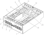
FIG. 1 is a schematic structural diagram of the present invention.
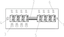
Fig. 2 is a front view of the present invention.
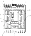
Fig. 3 is a rear view of the present invention.
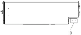
Fig. 4 is a side view of the present invention.
Fig. 5 is a top view of the present invention.
Fig. 6 is a bottom view of the present invention.
Fig. 7 is a schematic circuit diagram of the present invention.
Wherein:
the device comprises a start-stop button 1, a 32A/2P miniature circuit breaker 2, a five-hole socket 3, a C10A miniature circuit breaker 4, a direct-current molded case circuit breaker 5, an indicating device 6, an anti-reverse diode 7, a direct-current filter capacitor 8, a cooling fan 9, an incoming high-current terminal 10, a single-core outgoing high-current terminal 11, a direct-current C19 socket 12, an outgoing branch power indicator 13, a surge protection miniature circuit breaker 14, a direct-current surge protector 15, an alternating-current input plug-in terminal 16, a communication terminal 17, a DC12V output terminal 18, an acquisition device 19, a current Hall sensor 20, a honeycomb air inlet and outlet hole 21 and a mounting plate 22.
Detailed Description
For a better understanding of the technical aspects of the present invention, reference will now be made in detail to the accompanying drawings. It should be understood that the following specific examples are not intended to limit the embodiments of the present invention, but are merely exemplary embodiments of the present invention. It should be noted that the description of the positional relationship of the components, such as the component a is located above the component B, is based on the description of the relative positions of the components in the drawings, and is not intended to limit the actual positional relationship of the components.
Example 1:
referring to fig. 1-7, fig. 1 depicts a schematic structural diagram of the present invention. As shown in the figure, the large-current direct-current power distribution cabinet comprises a cabinet, wherein an anti-reverse diode 7, a direct-current filter capacitor 8, a cooling fan 9, an incoming line large-current terminal 10, an acquisition device 19 and a current hall sensor 20 are arranged in the cabinet; the acquisition device 19 is arranged in the middle of the case, the left side and the right side of the acquisition device 19 are respectively provided with an anti-reflection diode 7, the sides of the anti-reflection diodes 7 are respectively provided with a radiator, and the rear end of the radiator is provided with a radiating fan 9; a current Hall sensor 20 is arranged above the anti-reverse diode 7, a row of four direct current filter capacitors 8 are arranged behind the acquisition device 19, and the bottoms of the direct current filter capacitors 8 are fixed on the case by screws; the lower part of the rear end face of the case is provided with a concave embedding part, and the concave embedding part is provided with a row of incoming line heavy current terminals 10.
The front end face of the case is also provided with a start-stop button 1, a 32A/2P miniature circuit breaker 2, a five-hole socket 3, a C10A miniature circuit breaker 4, a direct-current plastic-shell circuit breaker 5 and an indicating device 6, the middle part of the front end face of the case is provided with four parallel 32A/2P miniature circuit breakers 2, the left side and the right side of the 32A/2P miniature circuit breaker 2 are respectively provided with four direct-current plastic-shell circuit breakers 5, a mounting mode of plate rear connecting wires is adopted, four five-hole sockets 3 are arranged below the direct-current plastic-shell circuit breakers 5, a row of eight indicating devices 6 are arranged above the direct-current plastic-shell circuit breaker 5, the leftmost side of the 32A/2P miniature circuit breaker 2 is provided with a C10A miniature circuit breaker 4 for power supply protection and maintenance switch of the five-hole socket 3, the rightmost side of the 32A/2P miniature circuit breaker 2 is provided with a start-stop button 1, for opening and closing the circuit breaker trip function.
The rear end face of the case is further provided with a single-core outgoing line large current terminal 11, a direct current C19 socket 12, outgoing line shunt power supply indicator lamps 13, a surge protection miniature circuit breaker 14, a direct current surge protector 15, an alternating current input plug-in terminal 16, a communication terminal 17 and a DC12V output terminal 18, a left group and a right group of single-core outgoing line large current terminals 11 are arranged above the incoming line large current terminal 10, eight single-core outgoing line large current terminals 11 in each group are arranged in two rows and four columns, eight direct current C19 sockets 12 and two direct current surge protectors 15 are arranged between the two groups of single-core outgoing line large current terminals 11, eight direct current C19 sockets 12 are arranged in two rows and four columns, two surge protection miniature circuit breakers 14 are arranged above the two direct current surge protectors 15, one row of eight outgoing line shunt power supply indicator lamps 13 are arranged above the single-core outgoing line large current terminals 11 and are used for judging and displaying whether the shunt circuit breakers are switched on, an alternating current input plug terminal 16, a communication terminal 17 and a DC12V output terminal 18 are arranged above the direct current C19 socket 12.
The bottom surface of the case is provided with two honeycomb hole arrays, and each honeycomb hole array comprises a plurality of honeycomb air inlet and outlet holes 21 for heat dissipation; two detachable mounting plates 22 are provided between the two honeycomb hole arrays for maintenance.
The working principle is as follows:
1. the design of a remote tripping function start-stop button is as follows:
according to the utility model, the small button switch is added in the secondary control loop and is arranged on the front panel of the case module to play a role in starting and closing the tripping function of the circuit breaker, the outgoing line shunt circuit breaker has a remote control shunt tripping function, the function can be closed or started through the button, the button has two groups of nodes, and the function of controlling the starting and stopping of two paths of shunt tripping through one button can be realized.
2. Design of miniature circuit breaker for protecting C19 output terminal:
the front face of the case module is provided with 4 32A/2P miniature circuit breakers, overload and short-circuit protection of C19 output terminals are provided, and each miniature circuit breaker is connected with 2C 19 output terminals and 8C 19 output terminals in total.
3. Designing a five-hole socket:
the front panel of the chassis module is provided with 4 five-hole sockets for on-site alternating current power supply, and the chassis module can be used for on-site operation and maintenance.
4. Design of an alternating-current miniature circuit breaker:
the front panel of the chassis module is provided with 1C 10A miniature circuit breaker for supplying power to 4 five-hole sockets for protection and maintenance.
5. The design of the direct current output shunt circuit breaker with the plastic shell comprises the following steps:
the front panel of the case module is provided with 8 direct current molded case circuit breakers of 2P200A, and the adopted mounting mode of wiring behind the board is that copper bars inside the case module are lapped, so that a more convenient mounting space and an electrical safety distance are provided for the inside of the case. Wherein, every 4 moulded case circuit breakers are one way, A, B two ways of independent operation altogether, and A way has 4 direct current output shunts promptly, and B way also has 4 direct current output shunts. Meanwhile, the plastic case circuit breaker is provided with an MX shunt release and an OF auxiliary contact for remotely controlling the opening and closing OF the circuit breaker and acquiring the opening and closing state OF the circuit breaker at present.
6. The input power supply indicating device is designed as follows:
the front panel of the case module is provided with 8 indicating devices which represent the power state of an incoming line input power supply and input reverse connection prevention alarm indication, and the sequence from left to right is that an A path input power supply 1, an A path input power supply 1 are in reverse connection alarm, an A path input power supply 2 are in reverse connection alarm, a B path input power supply 1 are in reverse connection alarm, a B path input power supply 2 and a B path input power supply 2 are in reverse connection alarm;
the working power supply adopted by the indicator light and the buzzer is DC24V, the direct current input voltage range of the system is 280V-420V, so the indicator light and the buzzer without high voltage are provided, 4 paths of input are respectively provided with a wide-range direct current input switching power supply, and output DC24V is supplied to 4 DC24V intermediate relay coils;
meanwhile, the AMC16Z-ZD main module adopted by the utility model determines whether an incoming line power supply is reversely connected by judging the direction of the input current, and triggers DO output action after the reverse connection, wherein DO main connection points are respectively connected in series in a power supply loop of a DC24 relay coil; the normally open power indicator of the intermediate relay, the normal close connects the buzzer, supply power and adopt DC24V that the switching power supply outputs too, namely when there is voltage to connect reversely, the input power indicator lights; when the voltage and current directions are opposite, the input voltage indicator lamp is turned off, and the reverse connection buzzer sounds; when no voltage is input, the switch voltage is not output, and the input power indicator light is not on.
7. And (3) designing an anti-reverse diode and a radiator:
because the input voltage is high and the current is large, the anti-reverse diode is arranged to meet the requirement of high voltage and large current, and meanwhile, the radiator is customized by considering the requirement of an internal installation space, so that the radiating problem under the condition of full load of the diode is met.
8. Designing a direct-current filter capacitor:
the utility model increases the design of the direct current filter capacitor, is used for reducing interference and filtering effects, customizes the 500V direct current filter capacitor, considers the installation space and is convenient to install, and adopts a bottom screw type fixing structure to ensure the convenience of capacitor installation.
9. Designing a heat radiation fan:
the heat radiation fan is arranged at the rear part of the heat radiator of the anti-reverse diode and used for blowing air, so that the heat radiation effect is improved, meanwhile, the fan is provided with a fault dry contact point and can be connected into the acquisition module to judge whether the fan is abnormal or not, so that the effects of maintaining and overhauling the fan are achieved, and the effects of heat radiation safety and stability are improved.
10. Designing an incoming line large-current terminal:
according to the incoming line input large-current external copper bar terminal, 770A large current can be met, 2 240mm cables can be connected, and meanwhile, the design of the installation space is considered, the overall depth is not prone to being too deep, and meanwhile, the connection of the cables does not affect the connection of other cables, so that the design of the concave-embedded type of the rear bottom of the case module is designed.
11. Designing an outgoing line large-current direct-current plug-in:
the rear panel of the chassis module is provided with 16 single-core outgoing line 200A heavy current terminals, and a fast-plug scheme is adopted, so that the installation and maintenance are convenient; the positive and negative are distinguished through different colors, and the identification is convenient.
12. C19 dc card design:
the rear panel of the chassis module is provided with 8 three-hole direct current C19 sockets, and the chassis module has a locking function and improves the reliability of plug-in units.
13. The design of the outgoing line shunt power supply indicator lamp:
the front of the case module is provided with a row of outgoing line shunt power indicator lamps which can display whether the shunt circuit breaker is switched on or not and whether an output terminal is electrified or not, so that a safety warning effect is provided; the indicating lamp adopts a DC24 power supply, and the control part indicates through the auxiliary contact of the outgoing line shunt molded case circuit breaker, so that whether the outgoing line shunt circuit breaker is switched on or not is determined.
14. The design of the surge protection miniature circuit breaker:
the back panel of the case module is provided with a 2-path direct current surge protection miniature circuit breaker.
15. DC surge protector design
The rear panel of the chassis module is provided with the 2-path direct current surge protector so as to improve the inrush current protection capability of a direct current loop.
16. Designing an alternating current input plug terminal:
the input power supply of the alternating current loop adopts a plug-in terminal design, and input current electricity supplies power to the alternating current five-hole socket on the front side of the case module after passing through the miniature circuit breaker on the front side of the case module, so that an alternating current maintenance power supply is provided.
17. Designing a communication terminal:
the rear panel of the case module is provided with a communication terminal for providing communication between the intelligent acquisition module and the background, and the communication adopts an RS485 modbus protocol, so that the case can realize remote data interaction, and functions of remote measurement, remote signaling, remote control and the like.
18. DC12V output terminal design:
the rear panel of the case module is provided with a DC12V output terminal for the decorative lamp to distribute power, and the total load capacity is 12W.
19. The intelligent acquisition device is designed:
the built-in acquisition device can acquire incoming line current, voltage and output shunt current; the temperature and humidity of the air inlet can be collected; the on-off state of the switch or the fuse can be collected; the state of the stop feedback of the cooling fan can be collected; the failure state of the lightning protection device can be collected; the switch shunt tripping can be respectively controlled through a protocol.
20. Designing a current Hall sensor:
the circuit of the utility model is provided with a current Hall sensor used for detecting direct current input and output current.
21. The bottom honeycomb holes of the case module are designed as follows:
the bottom surface of the case module is provided with honeycomb air inlet and outlet holes, so that the radiator and the fan can perform air cooling heat dissipation.
22. And (3) designing a maintenance scheme plate:
the bottom of the case module is provided with the detachable mounting plate, so that the fan replacement and the diode repair and replacement are facilitated.
The above is only a specific application example of the present invention, and the protection scope of the present invention is not limited in any way. All the technical solutions formed by equivalent transformation or equivalent replacement fall within the protection scope of the present invention.
Claims (10)
1. The utility model provides a heavy current DC power supply distribution cabinet which characterized in that: the high-voltage direct-current power supply comprises a case, wherein an anti-reverse diode (7), a direct-current filter capacitor (8), a cooling fan (9), an incoming line large-current terminal (10), an acquisition device (19) and a current Hall sensor (20) are arranged in the case; the collecting device (19) is arranged in the middle of the case, anti-reverse diodes (7) are arranged on the left side and the right side of the collecting device (19) respectively, the anti-reverse diodes (7) are provided with radiators, current Hall sensors (20) are arranged above the anti-reverse diodes (7), a row of direct current filter capacitors (8) are arranged behind the collecting device (19), and a row of incoming line heavy current terminals (10) are arranged on the rear end face of the case; be equipped with one row of miniature circuit breaker on the preceding terminal surface of machine case, miniature circuit breaker's the left and right sides is equipped with one row of direct current moulded case circuit breaker (5) respectively, the top of inlet wire heavy current terminal (10) of the rear end face of machine case is equipped with about two sets of single core heavy current terminals (11) of being qualified for the next round of competitions, is equipped with two way direct current surge protector (15) between two sets of single core heavy current terminals (11) of being qualified for the next round of competitions, and two way direct current surge protector (15) tops are equipped with two way surge protection miniature circuit breaker (14), still be equipped with communication terminal (17) and DC12V output terminal (18) on the rear end face of machine case.
2. A high current dc power distribution cabinet according to claim 1, wherein: the lower part of the rear end face of the case is provided with a concave embedding part, and the concave embedding part is provided with a row of incoming line large-current terminals (10).
3. A high current dc power distribution cabinet according to claim 1, wherein: and a heat radiation fan (9) is arranged at the rear end of the heat radiator of the anti-reflection diode (7).
4. A high current dc power distribution cabinet according to claim 1, wherein: the direct current plastic shell circuit breaker (5) is provided with a row of five-hole sockets (3) below, one side of the five-hole sockets (3) is provided with a C10A miniature circuit breaker (4), and the rear end face of the case is also provided with a current input by the alternating current input plug-in terminal (16) which supplies power to the five-hole sockets (3) after passing through the miniature circuit breaker, so that an alternating current maintenance power supply is provided.
5. A high current dc power distribution cabinet according to claim 1, wherein: and a row of indicating devices (6) are arranged above the direct current molded case circuit breaker (5), and the power state and the input of the representative incoming line input power supply are indicated by anti-reverse connection alarm.
6. A high current dc power distribution cabinet according to claim 1, wherein: the front end face of the case is also provided with a start-stop button (1) for starting and closing the tripping function of the circuit breaker.
7. A high current dc power distribution cabinet according to claim 1, wherein: and a row of eight outgoing line shunt power supply indicator lamps (13) are arranged above the single-core outgoing line high-current terminal (11).
8. A high current dc power distribution cabinet according to claim 1, wherein: the rear end face of the case is also provided with a plurality of direct current C19 sockets (12).
9. A high current dc power distribution cabinet according to claim 1, wherein: the bottom surface of machine case is equipped with two honeycomb hole arrays, and every honeycomb hole array contains a plurality of honeycombs and advances exhaust vent (21) for the heat dissipation.
10. A high current dc power distribution cabinet according to claim 1, wherein: the bottom surface of the case is also provided with at least one detachable mounting plate (22) for maintenance.
Priority Applications (1)
| Application Number | Priority Date | Filing Date | Title |
|---|---|---|---|
| CN202220787095.6U CN217010085U (en) | 2022-04-07 | 2022-04-07 | Heavy current DC power supply distribution cabinet |
Applications Claiming Priority (1)
| Application Number | Priority Date | Filing Date | Title |
|---|---|---|---|
| CN202220787095.6U CN217010085U (en) | 2022-04-07 | 2022-04-07 | Heavy current DC power supply distribution cabinet |
Publications (1)
| Publication Number | Publication Date |
|---|---|
| CN217010085U true CN217010085U (en) | 2022-07-19 |
Family
ID=82375184
Family Applications (1)
| Application Number | Title | Priority Date | Filing Date |
|---|---|---|---|
| CN202220787095.6U Active CN217010085U (en) | 2022-04-07 | 2022-04-07 | Heavy current DC power supply distribution cabinet |
Country Status (1)
| Country | Link |
|---|---|
| CN (1) | CN217010085U (en) |
-
2022
- 2022-04-07 CN CN202220787095.6U patent/CN217010085U/en active Active
Similar Documents
| Publication | Publication Date | Title |
|---|---|---|
| CN216082974U (en) | Intelligent bus monitoring system | |
| CN217010085U (en) | Heavy current DC power supply distribution cabinet | |
| CN211184586U (en) | Outdoor ETC rack | |
| WO2021163933A1 (en) | Power conversion device, and power supply system | |
| CN210898542U (en) | Filtering reactive power compensation device | |
| CN114976920A (en) | Large-current direct-current power supply distribution device with anti-reverse redundancy loop monitoring and acquisition function | |
| CN104734031A (en) | Power distribution cabinet special for low-voltage distribution system | |
| CN203645207U (en) | Multifunctional maintenance power case | |
| CN210183003U (en) | Remote intelligent control security monitoring box | |
| CN208862421U (en) | A kind of low-voltage comprehensive distribution box of modularized design | |
| CN208955640U (en) | A kind of Self-recover overvoltage-undervoltage protector | |
| CN219677786U (en) | Two-in one-out fast power generation car access box | |
| CN209561959U (en) | A kind of low-voltage distribution cabinet of stable structure | |
| CN214544077U (en) | Novel AC input unit equipment | |
| CN205986111U (en) | Modular scarce looks protection device of transformer | |
| CN217642164U (en) | Plug-in low-voltage cabinet power supply convenient to overhaul | |
| CN218997768U (en) | Power distribution control monitoring device | |
| CN220138940U (en) | Maintenance power supply box | |
| CN211701116U (en) | Intelligent power supply and distribution management equipment | |
| CN214429013U (en) | Reliable panel of direct current | |
| CN212908659U (en) | Low-voltage draw-out type incoming cabinet | |
| CN209544874U (en) | Intelligent power supply and distribution system | |
| CN205195050U (en) | Cubical switchboard of reliable power supply | |
| CN216648937U (en) | Low-voltage switchgear based on thing networking control | |
| CN219535295U (en) | JP switch board |
Legal Events
| Date | Code | Title | Description |
|---|---|---|---|
| GR01 | Patent grant | ||
| GR01 | Patent grant |