CN212764409U - Injection molding burr removes frock - Google Patents
Injection molding burr removes frock Download PDFInfo
- Publication number
- CN212764409U CN212764409U CN202021505769.6U CN202021505769U CN212764409U CN 212764409 U CN212764409 U CN 212764409U CN 202021505769 U CN202021505769 U CN 202021505769U CN 212764409 U CN212764409 U CN 212764409U
- Authority
- CN
- China
- Prior art keywords
- wall
- plate
- injection molding
- sliding
- lead screw
- Prior art date
- Legal status (The legal status is an assumption and is not a legal conclusion. Google has not performed a legal analysis and makes no representation as to the accuracy of the status listed.)
- Active
Links
Images


Landscapes
- Injection Moulding Of Plastics Or The Like (AREA)
Abstract
The utility model discloses an injection molding burr removes frock, comprises a workbench, be connected with the motor on the diapire of workstation, the output of motor passes the workstation and is connected with the rolling disc, be connected with clamping component on the roof of rolling disc, clamping component includes first backup pad, first backup pad is connected on the roof of rolling disc, be connected with the guide bar on the first backup pad roof, the connecting sleeve has been cup jointed on the guide bar outer wall, be connected with the motor on the connecting sleeve roof, the motor output passes the connecting sleeve and is connected with first lead screw, be connected with link assembly on the connecting sleeve outer wall, the link assembly one end of keeping away from the connecting sleeve is connected with the cardboard, still be provided with cutting assembly on the workstation roof, cutting assembly and clamping component cooperate; the utility model discloses a clamping assembly can make things convenient for quick fixes on operation platform the injection molding is stable, makes it can not take place the skew when unhairing limit to improve injection molding tubular product unhairing limit's quality and work efficiency.
Description
Technical Field
The utility model relates to an injection moulding product auxiliary assembly technical field especially relates to injection molding deckle edge gets rid of frock.
Background
Injection molding is a method for producing and molding industrial products. Products are generally produced by rubber injection molding and plastic injection molding; the injection molding can also be divided into injection molding and die casting; an injection molding machine (an injection machine or an injection molding machine for short) is a main molding device for making thermoplastic plastics or thermosetting materials into plastic products with various shapes by using a plastic molding die, and the injection molding is realized by the injection molding machine and the die.
In the injection molding tubular product production process, injection molding product often can produce deckle edge, thereby can influence the pleasing to the eye and the result of use of tubular product, consequently, need carry out deckle edge processing to it, and the work piece is when the deckle edge is handled, need utilize the frock to fix it with the injection molding, then utilize the cutter to carry out deckle edge processing, but fixed frock among the prior art is not only complicated in structure, and stability is relatively poor, thereby influence injection molding tubular product deckle edge's quality and efficiency, consequently, it is especially important that the frock is got rid of to injection molding deckle edge.
SUMMERY OF THE UTILITY MODEL
The utility model aims at solving the problem in the prior art, and the frock is got rid of to the injection molding deckle edge that proposes.
In order to achieve the above purpose, the utility model adopts the following technical scheme:
an injection molding part burr removing tool comprises a workbench, wherein a motor is connected to the bottom wall of the workbench, the output end of the motor penetrates through the workbench and is connected with a rotating disc, a clamping assembly is connected to the top wall of the rotating disc and comprises a first supporting plate, the first supporting plate is connected to the top wall of the rotating disc, a guide rod is connected to the top wall of the first supporting plate, a connecting sleeve is sleeved on the outer wall of the guide rod, a motor is connected to the top wall of the connecting sleeve, the output end of the motor penetrates through the connecting sleeve and is connected with a first lead screw, one end, far away from the motor, of the first lead screw is in threaded connection with the guide rod, a connecting rod assembly is connected to the outer wall of the connecting sleeve, one end, far away from the connecting sleeve, of the connecting rod assembly is connected with a clamping plate, the clamping plate is in, the cutting assembly cooperates with the clamping assembly.
Preferably, the frock is got rid of to injection molding deckle edge, link assembly includes first connecting plate, second connecting plate and connecting rod, first connecting plate is connected on the connecting sleeve outer wall, the connecting rod rotates to be connected on first connecting plate outer wall, just the one end that first connecting plate was kept away from to the connecting rod rotates with the second connecting plate and links to each other, the second connecting plate is connected on the cardboard inner wall.
Preferably, the frock is got rid of to injection molding deckle edge, it has the spout to cut on the first backup pad roof, the cardboard passes through slider sliding connection in the spout.
Preferably, the frock is got rid of to injection molding deckle edge, cutting assembly includes the fixing base, the fixing base is connected on the workstation roof, be connected with first handle on the fixing base outer wall, be connected with second lead screw and slide bar on the fixing base inner wall, threaded connection has first slide on the second lead screw outer wall, first slide slides with the slide bar and links to each other, just the one end of second lead screw is passed the fixing base and is linked to each other with first handle, be provided with lifting unit on the first slide roof, be connected with the cutter on the lifting unit outer wall.
Preferably, the frock is got rid of to injection molding deckle edge, the lifting unit support frame, be connected with the second handle on the support frame roof, be connected with the third lead screw on the second handle inner wall, the one end that the second handle was kept away from to the third lead screw passes the support frame and connects on first slide roof, threaded connection has the second slide on the third lead screw outer wall, just the second slide slides with the support frame and links to each other, the cutter is connected on the second slide outer wall.
Compared with the prior art, the utility model provides a frock is got rid of to injection molding deckle edge possesses following beneficial effect:
1. this frock is got rid of to injection molding deckle edge is through being provided with clamping component to can make things convenient for quick fix the injection molding stable on operation platform, make it can not take place the skew when unhairing limit, thereby improve injection molding tubular product unhairing limit's quality and work efficiency.
2. This frock is got rid of to injection molding deckle edge through the spout that sets up to stability when can guaranteeing the cardboard and slide, and then effectively improve the fixed effect to the work piece.
3. This frock is got rid of to injection molding deckle edge through the cutting assembly who sets up to when through starter motor, can be automatic carry out the deckle edge to fixing the work piece on the workstation and handle, and then effectual reduction intensity of labour, improve work efficiency.
4. This frock is got rid of to injection molding deckle edge through the first slide and the second slide that set up to can drive the sharpener and remove in the X, Z planes, and then adjust for the position of sharpener, thereby increase the device's practicality.
The device does not relate to the part and all is the same with prior art or can adopt prior art to realize, the utility model discloses a be provided with clamping component to can make things convenient for quick fix the injection molding stable on operation platform, make it can not take place the skew when unhairing limit, thereby improve injection molding tubular product unhairing limit's quality and work efficiency.
Drawings
Fig. 1 is a schematic structural view of the injection molding burr removing tool provided by the present invention;
FIG. 2 is a top view of the injection molding burr removing tool according to the present invention;
fig. 3 is a schematic structural view of a clamping assembly of the injection molding burr removing tool according to the present invention;
FIG. 4 is a cross-sectional view of the injection molding burr removing tooling clamping assembly provided by the present invention;
fig. 5 is the utility model provides an injection molding deckle edge gets rid of frock cutting assembly's schematic structure.
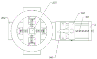
In the figure: 1. a work table; 2. a motor; 201. rotating the disc; 202. a first support plate; 203. a guide bar; 204. a connecting sleeve; 205. a motor; 206. a first lead screw; 207. clamping a plate; 208. a first connecting plate; 209. a second connecting plate; 210. a connecting rod; 211. a chute; 3. a fixed seat; 301. a second lead screw; 302. a first slide plate; 303. cutting; 304. a slide bar; 305. a support frame; 306. a third screw rod; 307. a second slide plate.
Detailed Description
The technical solutions in the embodiments of the present invention will be described clearly and completely with reference to the accompanying drawings in the embodiments of the present invention, and it is obvious that the described embodiments are only some embodiments of the present invention, not all embodiments.
In the description of the present invention, it is to be understood that the terms "upper", "lower", "front", "rear", "left", "right", "top", "bottom", "inner", "outer", and the like indicate orientations or positional relationships based on the orientations or positional relationships shown in the drawings, and are only for convenience of description and simplicity of description, and do not indicate or imply that the device or element being referred to must have a particular orientation, be constructed and operated in a particular orientation, and therefore, should not be construed as limiting the present invention.
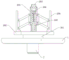
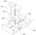
Referring to fig. 1-5, a burr removing tool for an injection molding part comprises a workbench 1, a motor 2 is connected to the bottom wall of the workbench 1, the output end of the motor 2 penetrates through the workbench 1 and is connected with a rotating disc 201, a clamping assembly is connected to the top wall of the rotating disc 201 and comprises a first supporting plate 202, the first supporting plate 202 is connected to the top wall of the rotating disc 201, a guide rod 203 is connected to the top wall of the first supporting plate 202, a connecting sleeve 204 is sleeved on the outer wall of the guide rod 203, a motor 205 is connected to the top wall of the connecting sleeve 204, the output end of the motor 205 penetrates through the connecting sleeve 204 and is connected with a first lead screw 206, one end of the first lead screw 206, which is far away from the motor 205, is in threaded connection with the guide rod 203, a connecting rod assembly is connected to the outer wall of the connecting sleeve 204, and one end of, the clamping plate 207 is connected with the first supporting plate 202 in a sliding mode, and a cutting assembly is further arranged on the top wall of the workbench 1 and matched with the clamping assembly;
the connecting rod assembly comprises a first connecting plate 208, a second connecting plate 209 and a connecting rod 210, wherein the first connecting plate 208 is connected to the outer wall of the connecting sleeve 204, the connecting rod 210 is rotatably connected to the outer wall of the first connecting plate 208, one end, far away from the first connecting plate 208, of the connecting rod 210 is rotatably connected with the second connecting plate 209, and the second connecting plate 209 is connected to the inner wall of the clamping plate 207;
a sliding groove 211 is drilled on the top wall of the first supporting plate 202, and the clamping plate 207 is slidably connected in the sliding groove 211 through a sliding block;
the cutting assembly comprises a fixed seat 3, the fixed seat 3 is connected to the top wall of the workbench 1, a first handle is connected to the outer wall of the fixed seat 3, a second lead screw 301 and a sliding rod 304 are connected to the inner wall of the fixed seat 3, a first sliding plate 302 is connected to the outer wall of the second lead screw 301 in a threaded manner, the first sliding plate 302 is connected with the sliding rod 304 in a sliding manner, one end of the second lead screw 301 penetrates through the fixed seat 3 and is connected with the first handle, a lifting assembly is arranged on the top wall of the first sliding plate 302, and a cutter 303 is connected to the outer wall of the lifting assembly;
a second handle is connected to the top wall of the supporting frame 305, a third screw 306 is connected to the inner wall of the second handle, one end, far away from the second handle, of the third screw 306 penetrates through the supporting frame 305 and is connected to the top wall of the first sliding plate 302, a second sliding plate 307 is connected to the outer wall of the third screw 306 in a threaded manner, the second sliding plate 307 is connected with the supporting frame 305 in a sliding manner, and the cutter 303 is connected to the outer wall of the second sliding plate 307;
in the utility model, when in use, the workpiece sleeve is placed on the periphery of the clamping component, then the motor 205 is started to drive the first lead screw 206 connected with the output end of the motor 205 to rotate, the first lead screw 206 is in threaded connection with the guide rod 203, and the first lead screw 206 can move downwards along the guide rod 203 when rotating, and further drives the connecting sleeve 204 to move downwards, so as to drive the connecting rod 210 to move downwards and rotate with the end connected with the outer wall of the connecting sleeve 204, and further generate outward thrust to the clamping plate 207, and the clamping plate 207 is connected in the chute 211 on the first supporting plate 202 in a sliding way, so that the clamping plate 207 slides outwards along the chute 211, thereby conveniently and rapidly fixing the injection molding piece on the operating platform stably, and the injection molding piece can not deviate when deburring, thereby improving the deburring quality and working efficiency of injection molding piece pipe products, and then adjusting the cutting component, during adjustment, the first handle is rotated to drive the second screw rod 301 to rotate, the slide rod 304 is arranged, and then the first sliding plate 302 connected with the second screw rod 301 in a threaded manner is driven to move left and right in an X plane, so that the cutter 303 is driven to move left and right along the X plane, the second handle is rotated to drive the third screw rod 306 to rotate, and then the second sliding plate 307 connected with the outer wall of the cutter 303 in a threaded manner is driven to move up and down in a Z plane along the support frame 305, so that the height of the cutter 303 is adjusted to act on a workpiece to be subjected to burr removal, the motor 2 is started to drive the rotating disc 201 connected with the output end of the motor to rotate, so that the clamping assembly and the workpiece to be subjected to burr removal are driven to rotate, and the height and distance of the cutter 303 can be adjusted, so that the cutter can be suitable for workpieces of different models, and then its practicality of effectual improvement can be through the spout 211 that sets up to can make the stable slip that slides of cardboard 207, and then effectively improve the fixed effect to the work piece.
The above, only be the concrete implementation of the preferred embodiment of the present invention, but the protection scope of the present invention is not limited thereto, and any person skilled in the art is in the technical scope of the present invention, according to the technical solution of the present invention and the utility model, the concept of which is equivalent to replace or change, should be covered within the protection scope of the present invention.
Claims (5)
1. The utility model provides a frock is got rid of to injection molding deckle edge, includes workstation (1), its characterized in that, be connected with motor (2) on the diapire of workstation (1), the output of motor (2) passes workstation (1) and is connected with rolling disc (201), be connected with clamping component on the roof of rolling disc (201), clamping component includes first backup pad (202), first backup pad (202) are connected on the roof of rolling disc (201), be connected with guide bar (203) on first backup pad (202) roof, connecting sleeve (204) have been cup jointed on guide bar (203) outer wall, be connected with motor (205) on connecting sleeve (204) roof, motor (205) output passes connecting sleeve (204) and is connected with first lead screw (206), the one end that motor (205) were kept away from to first lead screw (206) links to each other with guide bar (203) screw thread, the outer wall of the connecting sleeve (204) is connected with a connecting rod assembly, one end, far away from the connecting sleeve (204), of the connecting rod assembly is connected with a clamping plate (207), the clamping plate (207) is connected with the first supporting plate (202) in a sliding mode, the top wall of the workbench (1) is further provided with a cutting assembly, and the cutting assembly is matched with the clamping assembly.
2. The injection molding piece burr removing tool according to claim 1, characterized in that the connecting rod assembly comprises a first connecting plate (208), a second connecting plate (209) and a connecting rod (210), the first connecting plate (208) is connected to the outer wall of the connecting sleeve (204), the connecting rod (210) is rotatably connected to the outer wall of the first connecting plate (208), one end of the connecting rod (210) far away from the first connecting plate (208) is rotatably connected with the second connecting plate (209), and the second connecting plate (209) is connected to the inner wall of the clamping plate (207).
3. The injection molding piece burr removing tool according to claim 2, wherein a sliding groove (211) is formed in the top wall of the first support plate (202), and the clamping plate (207) is slidably connected in the sliding groove (211) through a sliding block.
4. The injection molding part burr removing tool according to claim 1, characterized in that the cutting assembly comprises a fixed seat (3), the fixed seat (3) is connected to the top wall of the workbench (1), the outer wall of the fixed seat (3) is connected with a first handle, the inner wall of the fixed seat (3) is connected with a second lead screw (301) and a sliding rod (304), the outer wall of the second lead screw (301) is connected with a first sliding plate (302) in a threaded manner, the first sliding plate (302) is connected with the sliding rod (304) in a sliding manner, one end of the second lead screw (301) penetrates through the fixed seat (3) and is connected with the first handle, a lifting assembly is arranged on the top wall of the first sliding plate (302), and the outer wall of the lifting assembly is connected with a cutter (303).
5. The injection molding burr removing tool according to claim 4, characterized in that a second handle is connected to the top wall of the lifting assembly support frame (305), a third lead screw (306) is connected to the inner wall of the second handle, one end, away from the second handle, of the third lead screw (306) penetrates through the support frame (305) and is connected to the top wall of the first sliding plate (302), a second sliding plate (307) is connected to the outer wall of the third lead screw (306) in a threaded manner, the second sliding plate (307) is connected to the support frame (305) in a sliding manner, and the cutting knife (303) is connected to the outer wall of the second sliding plate (307).
Priority Applications (1)
| Application Number | Priority Date | Filing Date | Title |
|---|---|---|---|
| CN202021505769.6U CN212764409U (en) | 2020-07-27 | 2020-07-27 | Injection molding burr removes frock |
Applications Claiming Priority (1)
| Application Number | Priority Date | Filing Date | Title |
|---|---|---|---|
| CN202021505769.6U CN212764409U (en) | 2020-07-27 | 2020-07-27 | Injection molding burr removes frock |
Publications (1)
| Publication Number | Publication Date |
|---|---|
| CN212764409U true CN212764409U (en) | 2021-03-23 |
Family
ID=75039209
Family Applications (1)
| Application Number | Title | Priority Date | Filing Date |
|---|---|---|---|
| CN202021505769.6U Active CN212764409U (en) | 2020-07-27 | 2020-07-27 | Injection molding burr removes frock |
Country Status (1)
| Country | Link |
|---|---|
| CN (1) | CN212764409U (en) |
Cited By (1)
| Publication number | Priority date | Publication date | Assignee | Title |
|---|---|---|---|---|
| CN118254314A (en) * | 2024-05-31 | 2024-06-28 | 山东威阳医疗器械科技有限公司 | Production device and manufacturing method of bone screw baffle |
-
2020
- 2020-07-27 CN CN202021505769.6U patent/CN212764409U/en active Active
Cited By (1)
| Publication number | Priority date | Publication date | Assignee | Title |
|---|---|---|---|---|
| CN118254314A (en) * | 2024-05-31 | 2024-06-28 | 山东威阳医疗器械科技有限公司 | Production device and manufacturing method of bone screw baffle |
Similar Documents
| Publication | Publication Date | Title |
|---|---|---|
| CN110900682B (en) | Trimming device of energy-saving electronic circuit board | |
| CN212764409U (en) | Injection molding burr removes frock | |
| CN219520219U (en) | Automobile bevel cutting and trimming composite stamping die | |
| CN113084255A (en) | Carbide milling cutter processingequipment of convenient adjustment depth of cut | |
| CN112476898A (en) | Plastic product side cut equipment for chemical production | |
| CN210362120U (en) | Injection molding burr removal equipment | |
| CN110744319A (en) | Bedroom boring machine of adjustable material angle | |
| CN107159950B (en) | Tool and method for trimming forming plate | |
| CN206718060U (en) | New both-end numerical control tenon milling machine | |
| CN212496442U (en) | Numerical control composite heat-insulation air pipe cutting machine | |
| CN213471289U (en) | Adjustable efficient cutting device for rubber and plastic foam hoses | |
| CN212123982U (en) | Trimming jig for automobile handle injection molding piece | |
| CN211939343U (en) | Arc-shaped groove slotting device of high-precision refrigerator punching die | |
| CN209793436U (en) | Automatic copying grinding equipment | |
| CN209983617U (en) | Radium-shine lathe tool equipment of jewelry production usefulness | |
| CN110757170A (en) | Steel strip welding and grinding all-in-one machine and working method thereof | |
| CN221210884U (en) | Cutting machine is used in processing of car spare part | |
| CN215790904U (en) | Special-shaped glass cutting machine | |
| CN219093365U (en) | Modular spare part side cut plastic mould | |
| CN214643852U (en) | Batch flash repairing device for plastic basin production | |
| CN216151275U (en) | Multidirectional cutting device for part machining | |
| CN209937058U (en) | Decorative strip corner cutting machine | |
| KR101525058B1 (en) | Cutting Method for Scrapping Using Non-rotating Special Jig | |
| CN214979377U (en) | High-precision cutter die of high-speed milling die | |
| CN215837691U (en) | Mobile drawing device of computer cutting and drawing instrument |
Legal Events
| Date | Code | Title | Description |
|---|---|---|---|
| GR01 | Patent grant | ||
| GR01 | Patent grant |