CN110757170A - Steel strip welding and grinding all-in-one machine and working method thereof - Google Patents
Steel strip welding and grinding all-in-one machine and working method thereof Download PDFInfo
- Publication number
- CN110757170A CN110757170A CN201911270287.9A CN201911270287A CN110757170A CN 110757170 A CN110757170 A CN 110757170A CN 201911270287 A CN201911270287 A CN 201911270287A CN 110757170 A CN110757170 A CN 110757170A
- Authority
- CN
- China
- Prior art keywords
- welding
- grinding
- machine
- steel strip
- steel
- Prior art date
- Legal status (The legal status is an assumption and is not a legal conclusion. Google has not performed a legal analysis and makes no representation as to the accuracy of the status listed.)
- Pending
Links
Images


Classifications
-
- B—PERFORMING OPERATIONS; TRANSPORTING
- B23—MACHINE TOOLS; METAL-WORKING NOT OTHERWISE PROVIDED FOR
- B23P—METAL-WORKING NOT OTHERWISE PROVIDED FOR; COMBINED OPERATIONS; UNIVERSAL MACHINE TOOLS
- B23P23/00—Machines or arrangements of machines for performing specified combinations of different metal-working operations not covered by a single other subclass
- B23P23/04—Machines or arrangements of machines for performing specified combinations of different metal-working operations not covered by a single other subclass for both machining and other metal-working operations
Landscapes
- Physics & Mathematics (AREA)
- Optics & Photonics (AREA)
- Engineering & Computer Science (AREA)
- Mechanical Engineering (AREA)
- Grinding Of Cylindrical And Plane Surfaces (AREA)
- Grinding And Polishing Of Tertiary Curved Surfaces And Surfaces With Complex Shapes (AREA)
- Finish Polishing, Edge Sharpening, And Grinding By Specific Grinding Devices (AREA)
Abstract
The invention discloses a steel strip welding and grinding integrated machine and a working method thereof, belonging to the technical field of steel strip fastener production and comprising a machine base, a welding machine, a milling end mechanism and a grinding mechanism, wherein the welding machine and the grinding mechanism are arranged on a platform at the top of the machine base side by side, the milling end mechanism is arranged in front of the welding machine and comprises a moving table and a milling cutter, and the moving table clamps the ends of two steel strips and approaches the milling cutter rotating at high speed to complete the end milling work; the lower part of a welding head of the welding machine is fixedly connected with a fixture bottom plate, and the ends of the two steel belts are clamped on the fixture bottom plate to complete butt welding; and the welding area of the steel strip is fixed on the worktable of the coping mechanism by a fixture II, and the grinding wheel of the coping mechanism is used for coping the welding area. The steel strip welding and grinding integrated machine can weld steel strip joints together at high quality, finish the steel strip joints smoothly and tidily, reduce the frequency of steel strip replacement and improve the production efficiency.
Description
Technical Field
The invention relates to the technical field of production of steel strip fasteners, in particular to a steel strip welding and grinding all-in-one machine and a working method thereof.
Background
The steel band fasteners such as clamp, larynx hoop mainly use steel band raw and other materials to process the preparation in process of production, and when the punch press pay-off, because steel band raw and other materials reel is little, the repeated reloading number of times of every production shift is more, wastes time and energy and causes production efficiency low, and artifical repeated feeding appears tired operation easily moreover and causes the accident of industrial safety.
The joints of the steel strip raw material reels are connected in series and welded together, so that the manual feeding times can be reduced, and the production efficiency is improved. However, in the butt welding machine in the prior art, the quality of the butt welding work of the steel strip is not high, the welding is irregular, the welding beading, the welding slag and the like exist, and the detection of the feeding probe of the punch cannot be normally carried out, so that the steel strip connection technology is not over-closed.
Therefore, the development of an integrated machine for welding and grinding steel strips to solve the above problems is a technical problem to be solved by those skilled in the art.
Disclosure of Invention
The invention aims to provide a steel strip welding and grinding all-in-one machine and a working method thereof, which can weld steel strip joints together with high quality and finish smoothly and tidily, reduce the frequency of steel strip replacement and improve the production efficiency.
In order to solve the technical problems, the invention adopts the following technical scheme:
the invention discloses a steel strip welding and grinding integrated machine which comprises a machine base, a welding machine, a milling end mechanism and a grinding mechanism, wherein the welding machine and the grinding mechanism are arranged on a platform at the top of the machine base side by side; the lower part of a welding head of the welding machine is fixedly connected with a fixture bottom plate, and the ends of the two steel belts are clamped on the fixture bottom plate to complete butt welding; and the welding area of the steel strip is fixed on the worktable of the coping mechanism by a fixture II, and the grinding wheel of the coping mechanism is used for coping the welding area.
Further, the welding machine is a resistance butt welding machine.
Further, tool clamps are arranged on two sides of the fixture bottom plate, fixed arms of the tool clamps are fixedly connected to the fixture bottom plate, and jaws of the tool clamp pressing arms clamp the steel belt on the fixture bottom plate.
Furthermore, the end milling mechanism further comprises a screw rod handle, a first fixture, a speed reducing motor and a groove, the end of the screw rod handle is clamped at the rear part of the mobile station and drives the mobile station to move back and forth, the two side-by-side fixtures clamp the ends of the steel belts, the groove is arranged in the middle of the front part of the mobile station and corresponds to the milling cutter, the milling cutter is driven to rotate by the speed reducing motor, and the ends of the two steel belts stretch into the groove.
Furthermore, the first fixture is connected to a sliding rail in a sliding mode, a vertical hole penetrating through the steel belt is formed in the bottom of the first fixture close to the sliding rail, and a top thread at a locking position is arranged at the top of the first fixture.
Further, the grinding mechanism further comprises a motor, an output shaft of the motor is connected with the grinding wheel, the motor is installed on a track platform, and the track platform can drive the grinding wheel to move and work along the vertical direction, the left direction, the right direction and the front direction and the back direction.
Furthermore, a cushion block for polishing the top surface of the steel strip is further arranged on the polishing mechanism workbench, a bottom plate of the cushion block is installed on the polishing mechanism workbench through a bolt, and the cushion block is arranged under the welding area.
Further, the grinding mechanism further comprises a lower grinding machine, the lower grinding machine is installed below the steel belt through a lower rail platform, and the lower grinding machine is used for grinding the lower surface of the welding area.
Correspondingly, the invention also provides a working method of the steel strip welding and grinding all-in-one machine, the steel strip is welded and ground by using any one of the steel strip welding and grinding all-in-one machines, and the working method comprises the following specific working steps:
firstly, clamping the ends of two steel belts by a moving platform of the end milling mechanism and approaching the milling cutter rotating at a high speed to finish end milling work so as to ensure that the ends are neat;
secondly, clamping the end heads of the two steel strips processed in the first step on the fixture bottom plate, starting the welding machine to complete butt welding work, and welding the two end heads together;
and thirdly, fixing the welded steel strip on the workbench of the grinding mechanism by using a second fixture, and grinding the welding area by using a grinding wheel of the grinding mechanism.
Further, in the third step, the grinding mechanism grinds four surfaces of the upper, lower, left, and right of the welding region.
Compared with the prior art, the invention has the beneficial technical effects that:
according to the steel strip welding and grinding integrated machine, the welding machine, the end milling mechanism and the grinding mechanism are integrated on one device, so that the end of a steel strip can be conveniently and sequentially milled, welded and ground, the cutting burrs and the bevel edges of a raw material steel coil are removed through the milling operation of the alloy bar milling cutter of the end milling mechanism, the verticality between the short edge and the long edge of the end is ensured, the burrs are removed, and preparation is made for accurate welding; the arrangement of the clamp base plate is convenient for fixing the steel belt, so that the butt joint is welded smoothly when a welding machine is used for welding; through the setting of coping mechanism, be convenient for get rid of the beading and the welding burr that form during the welding, guaranteed that welding area's size and outward appearance are similar with the steel band, guarantee normally through the detection of the pan feeding probe of punch press. The steel strip welding and grinding integrated machine can weld steel strip joints together at high quality, finish the steel strip joints smoothly and tidily, reduce the frequency of steel strip replacement and improve the production efficiency.
In addition, through the arrangement of the tool clamp, the steel belt is conveniently clamped on the clamp bottom plate, so that the clamping is convenient and the positioning is accurate when the steel belt welding process is operated. The steel belts are fixedly clamped through the first clamping fixture, the ends of the steel belts are vertically inserted into the vertical holes, the milling cutters are guaranteed to mill the ends of the two steel belts simultaneously, the short edges of the ends are guaranteed to be neat, and the problem that the short edges of the ends are not neat due to large milling amount at an inlet when the steel belts are flatly installed is avoided. The grinding wheel is mounted on a track platform of a multilayer nested driving structure through a motor, so that grinding wheels can be driven to feed in the vertical, horizontal and front and back directions conveniently for grinding, the front side and the back side of a welding area can be ground, the top surface of the welding area can be ground by matching with the use of a cushion block, and the bottom surface of the welding area can be ground after a steel belt is turned over; two convex ribs of the cushion block are supported on two sides of the lower part of the welding area, so that the condition that the positioning reference is inaccurate and grinding errors are easily caused due to the fact that the lower part of the welding area is directly supported can be avoided. Through the arrangement of the underneath type grinder, the lower surface of the welding area is convenient to grind, the upper surface, the lower surface, the left surface and the right surface of the welding area can be ground by one-time clamping, welding beading and burrs are removed, and grinding precision is guaranteed.
Drawings
The invention is further illustrated in the following description with reference to the drawings.
FIG. 1 is a schematic structural diagram of a top view of the steel strip welding and grinding integrated machine of the invention;
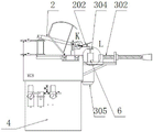
FIG. 2 is a side view schematic structural diagram of a welding machine part of the steel strip welding and grinding integrated machine;
FIG. 3 is a schematic front view structure diagram of a grinding mechanism of the steel strip welding and grinding all-in-one machine of the invention;
FIG. 4 is a partially enlarged view of the portion I in FIG. 1;
FIG. 5 is an enlarged view of a portion J of FIG. 1;
FIG. 6 is a partially enlarged view of the portion K in FIG. 2;
FIG. 7 is an enlarged view of a portion L of FIG. 2;
description of reference numerals: 1. a machine base; 2. a welding machine; 201. a fixture base plate; 202. clamping the tool; 3. end milling mechanisms; 301. a mobile station; 302. a lead screw handle; 303. milling cutters; 304. a first clamp; 305. a reduction motor; 306. a slide rail; 307. a groove; 4. an electric cabinet; 5. a grinding mechanism; 501. a motor; 502. a second clamping tool; 503. cushion blocks; 504. a grinding wheel; 505. a cylinder; 6. a steel belt; 601. a welding area.
Detailed Description
The core of the invention is to provide the steel strip welding and polishing all-in-one machine, which can weld steel strip joints together with high quality and smooth and tidy trimming, reduce the frequency of steel strip replacement and improve the production efficiency.
The technical solutions in the embodiments of the present invention will be described clearly and completely with reference to the accompanying drawings in the embodiments of the present invention, and it is obvious that the described embodiments are only a part of the embodiments of the present invention, and not all of the embodiments. All other embodiments, which can be derived by a person skilled in the art from the embodiments given herein without making any creative effort, shall fall within the protection scope of the present invention.
Referring to the accompanying drawings, FIG. 1 is a schematic structural view of a steel strip welding and grinding integrated machine in a top view; FIG. 2 is a side view schematic structural diagram of a welding machine part of the steel strip welding and grinding integrated machine; FIG. 3 is a schematic front view structure diagram of a grinding mechanism of the steel strip welding and grinding all-in-one machine of the invention; FIG. 4 is a partially enlarged view of the portion I in FIG. 1; FIG. 5 is an enlarged view of a portion J of FIG. 1; FIG. 6 is a partially enlarged view of the portion K in FIG. 2; fig. 7 is a partially enlarged view of a portion L of fig. 2.
In a specific embodiment, as shown in fig. 1 to 7, the steel strip welding and grinding all-in-one machine comprises a machine base 1, a welding machine 2, a milling end mechanism 3 and a grinding mechanism 5, wherein the welding machine 2 and the grinding mechanism 5 are arranged on a top platform of the machine base 1 side by side, an electric cabinet 4 is arranged below the top platform, and a power supply of the welding machine 2 and an electric control element of the grinding mechanism 5 are arranged in the electric cabinet 4; a milling end mechanism 3 is arranged in front of the welding machine 2, the milling end mechanism 3 comprises a moving platform 301 and a milling cutter 303, and the moving platform 301 clamps the ends of the two steel strips 6 and approaches the milling cutter 303 rotating at a high speed to complete end milling work; the lower part of a welding head of the welding machine 2 is fixedly connected with a fixture bottom plate 201, the end heads of the two steel strips 6 are clamped on the fixture bottom plate 201, and the welding machine 2 is started to complete butt welding work; the welding area 601 of the steel strip 6 is fixed on the worktable of the sharpening mechanism 5 by a second clamp 502, and the grinding wheel 504 of the sharpening mechanism 5 sharpens the welding area 601.
Specifically, the welder 2 is a resistance butt welder.
The integrated arrangement of the welding machine 2, the end milling mechanism 3 and the grinding mechanism 5 on one device is convenient for finishing the milling, welding and grinding work of the end of the steel belt 6 in sequence, the cutting burrs and the bevel edges of the raw material steel coil are removed through the milling and aligning work of the alloy bar milling cutter of the end milling mechanism 3, the verticality between the short edge and the long edge of the end is ensured, the burrs are removed, and the preparation is made for the accurate welding; the arrangement of the fixture bottom plate 201 is convenient for fixing the steel strip 6, so that the butt joint is welded smoothly when the welding machine 2 is welded; through the arrangement of the grinding mechanism 5, welding beading and welding burrs formed during welding can be removed conveniently, the size and the appearance of the welding area 601 are similar to those of the steel belt 6, and the detection of a feeding probe passing through a punch normally is ensured. The steel strip welding and grinding integrated machine can weld steel strip joints together at high quality, finish the steel strip joints smoothly and tidily, reduce the frequency of steel strip replacement and improve the production efficiency.
In a specific embodiment of the present invention, as shown in fig. 1, fig. 2 and fig. 6, tool clamps 202 are disposed on two sides of a fixture base plate 201, a fixed arm of the tool clamp 202 is fixedly connected to the fixture base plate 201, a movable jaw of the tool clamp 202 presses the arm to clamp a steel strip 6 on the fixture base plate 201, and a positioning clamping edge is further disposed on the fixture base plate 201 outside the movable jaw.
Through the arrangement of the tool clamp 202, the steel belt 6 is conveniently clamped on the clamp base plate 201, so that the steel belt 6 is convenient to clamp and accurate to position during the welding process.
In an embodiment of the present invention, as shown in fig. 1, 2 and 4, the end milling mechanism 3 further includes a screw handle 302, a first fixture 304, a speed reducing motor 305 and a groove 307, an end of the screw handle 302 is rotatably clamped at a rear portion of the moving platform 301 and drives the moving platform 301 to move back and forth, the first fixture 304 is disposed on the moving platform 301, two side-by-side first fixtures 304 clamp an end of the steel strip 6, the groove 307 is disposed at a middle position of a front portion of the moving platform 301, the groove 307 corresponds to the milling cutter 303, the milling cutter 303 is driven to rotate by the speed reducing motor 305, and the ends of the two steel strips 6 both protrude into the groove 307. The milling cutter 303 is specifically an alloy rod milling cutter.
Specifically, the first fixture 304 is slidably connected to the slide rail 306, the bottom of the first fixture 304 is provided with a vertical hole penetrating through the steel belt 6 near the slide rail 306, and the top of the first fixture 304 is provided with a top thread at a locking position.
The steel belt 6 is fixedly clamped through the first clamping fixture 304, the end of the steel belt 6 is vertically inserted into the vertical hole, the milling cutter 303 is guaranteed to mill the ends of the two steel belts 6 at the same time, the short edges of the ends are guaranteed to be neat, and the problem that the short edges of the ends are not neat due to large milling amount at an inlet when the steel belt is flatly installed is avoided.
In an embodiment of the present invention, as shown in fig. 1 and 3, the sharpening mechanism 5 further includes a motor 501, an output shaft of the motor 501 is connected to the grinding wheel 504, the motor 501 is mounted on a track platform, the track platform is a multi-layer nested driving structure, and the track platform can drive the grinding wheel 504 to feed along three directions, i.e., up and down, left and right, and front and back, so as to perform sharpening. The second fixture 502 comprises a C-shaped structure frame, an air cylinder 505 is hung on the top of the C-shaped structure frame, a piston rod of the air cylinder 505 is connected with a pressing plate, and the pressing plate presses the steel belts 6 on two sides of the welding area 601 tightly.
Specifically, a cushion block 503 used for grinding the top surface of the steel strip 6 is further arranged on the worktable of the grinding mechanism 5, a bottom plate of the cushion block 503 is mounted on the worktable of the grinding mechanism 5 through bolts, the cushion block 503 is cushioned under the welding area 601, and two convex ribs of the cushion block 503 are supported on two sides below the welding area 601.
The grinding wheel 504 is conveniently driven to feed in the vertical, horizontal and front-back directions to grind the front and back sides of the welding area 601 by the motor 501 arranged on a rail platform of a multilayer nested driving structure, the top surface of the welding area 601 can be ground by matching with the use of the cushion block 503, and the bottom surface of the welding area 601 can be ground after the steel belt 6 is turned over; two convex ribs of the cushion block 503 are supported on two sides of the lower part of the welding area 601, so that the condition that the positioning reference is inaccurate and grinding errors are easily caused due to the fact that the lower part of the welding area 601 is directly supported can be avoided.
In another embodiment of the present invention, the grinding mechanism 5 further includes a lower grinding machine, the lower grinding machine is mounted below the steel belt 6 through a lower track platform, the lower track platform is also a multi-layer nested driving structure, and the lower track platform drives the lower grinding machine to move up and down and back and forth, so as to grind the lower surface of the welding area 601.
Through the arrangement of the underneath type grinding machine, the lower surface of the welding area 601 is convenient to grind, the upper surface, the lower surface, the left surface and the right surface of the welding area 601 can be ground by one-time clamping, welding beading and burrs are removed, and grinding precision is guaranteed.
Based on the steel strip welding and grinding all-in-one machine of each embodiment, the invention also provides a working method of the steel strip welding and grinding all-in-one machine, the steel strip welding and grinding all-in-one machine in the embodiment is used for carrying out welding and grinding treatment on the steel strip 6, and the working method comprises the following specific working steps:
firstly, clamping the ends of two steel belts 6 by a moving platform 301 of an end milling mechanism 3 and approaching a milling cutter 303 rotating at a high speed to finish end milling work so as to ensure that the ends are neat;
secondly, clamping the end heads of the two steel belts 6 processed in the first step on a fixture bottom plate 201, starting a welding machine 2 to complete butt welding work, and welding the two end heads together;
thirdly, the welded steel strip 6 is fixed on a worktable of the sharpening mechanism 5 by using a second fixture 502, and a grinding wheel 504 of the sharpening mechanism 5 grinds the welding area 601.
Further, in the third step of the above-described operation method, the grinding mechanism 5 grinds four surfaces of the upper, lower, left, and right sides of the welding region 601.
According to the steel strip welding and grinding integrated machine, the welding machine 2, the end milling mechanism 3 and the grinding mechanism 5 are integrated on one device, so that the end of the steel strip 6 can be milled, welded and ground in sequence conveniently, the shearing burrs and the bevel edges of the raw material steel coil are removed through the milling operation of the alloy bar milling cutter of the end milling mechanism 3, the verticality between the short edge and the long edge of the end is ensured, the burrs are removed, and preparation is made for accurate welding; the arrangement of the fixture bottom plate 201 is convenient for fixing the steel strip 6, so that the butt joint is welded smoothly when the welding machine 2 is welded; through the arrangement of the grinding mechanism 5, welding beading and welding burrs formed during welding can be removed conveniently, the size and the appearance of the welding area 601 are similar to those of the steel belt 6, and the detection of a feeding probe passing through a punch normally is ensured. The steel strip welding and grinding integrated machine can weld steel strip joints together at high quality, finish the steel strip joints smoothly and tidily, reduce the frequency of steel strip replacement and improve the production efficiency. In addition, the steel belt 6 is conveniently clamped on the fixture bottom plate 201 through the arrangement of the tool clamp 202, so that the steel belt 6 is convenient to clamp and accurate to position during the welding process of the steel belt 6. The steel belt 6 is fixedly clamped through the first clamping fixture 304, the end of the steel belt 6 is vertically inserted into the vertical hole, the milling cutter 303 is guaranteed to mill the ends of the two steel belts 6 at the same time, the short edges of the ends are guaranteed to be neat, and the problem that the short edges of the ends are not neat due to large milling amount at an inlet when the steel belt is flatly installed is avoided. The grinding wheel 504 is conveniently driven to feed in the vertical, horizontal and front-back directions to grind the front and back sides of the welding area 601 by the motor 501 arranged on a rail platform of a multilayer nested driving structure, the top surface of the welding area 601 can be ground by matching with the use of the cushion block 503, and the bottom surface of the welding area 601 can be ground after the steel belt 6 is turned over; two convex ribs of the cushion block 503 are supported on two sides of the lower part of the welding area 601, so that the condition that the positioning reference is inaccurate and grinding errors are easily caused due to the fact that the lower part of the welding area 601 is directly supported can be avoided. Through the arrangement of the underneath type grinding machine, the lower surface of the welding area 601 is convenient to grind, the upper surface, the lower surface, the left surface and the right surface of the welding area 601 can be ground by one-time clamping, welding beading and burrs are removed, and grinding precision is guaranteed.
The above-described embodiments are merely illustrative of the preferred embodiments of the present invention, and do not limit the scope of the present invention, and various modifications and improvements of the technical solutions of the present invention can be made by those skilled in the art without departing from the spirit of the present invention, and the technical solutions of the present invention are within the scope of the present invention defined by the claims.
Claims (10)
1. The utility model provides a steel band welding coping all-in-one which characterized in that: the automatic end milling machine comprises a machine base (1), a welding machine (2), an end milling mechanism (3) and a grinding mechanism (5), wherein the welding machine (2) and the grinding mechanism (5) are arranged on a platform at the top of the machine base (1) side by side, the end milling mechanism (3) is arranged in front of the welding machine (2), the end milling mechanism (3) comprises a moving table (301) and a milling cutter (303), and the moving table (301) clamps the ends of two steel belts (6) and approaches the milling cutter (303) rotating at a high speed to complete end milling work; the lower part of a welding head of the welding machine (2) is fixedly connected with a fixture bottom plate (201), and the ends of the two steel belts (6) are clamped on the fixture bottom plate (201) to complete butt welding; the welding area (601) of the steel belt (6) is fixed on the workbench of the grinding mechanism (5) by a second fixture (502), and the grinding wheel (504) of the grinding mechanism (5) grinds the welding area (601).
2. The steel strip welding and grinding all-in-one machine as claimed in claim 1, characterized in that: the welding machine (2) is a resistance butt welding machine.
3. The steel strip welding and grinding all-in-one machine as claimed in claim 1 or 2, characterized in that: the steel strip clamping device is characterized in that the two sides of the fixture bottom plate (201) are provided with the tool clamps (202), the fixed arms of the tool clamps (202) are fixedly connected to the fixture bottom plate (201), and the jaws of the pressing arms of the tool clamps (202) clamp the steel strip (6) on the fixture bottom plate (201).
4. The steel strip welding and grinding all-in-one machine as claimed in claim 1, characterized in that: the end milling mechanism (3) further comprises a screw rod handle (302), a first fixture (304), a speed reducing motor (305) and a groove (307), the end portion of the screw rod handle (302) is clamped at the rear portion of the moving platform (301) and drives the moving platform (301) to move back and forth, the two side-by-side first fixtures (304) clamp the ends of the steel belts (6), the groove (307) is arranged in the middle of the front portion of the moving platform (301), the groove (307) corresponds to the milling cutter (303), the milling cutter (303) is driven to rotate by the speed reducing motor (305), and the ends of the two steel belts (6) are all inserted into the groove (307).
5. The steel strip welding and grinding all-in-one machine as claimed in claim 4, characterized in that: the first fixture (304) is connected to the sliding rail (306) in a sliding mode, a vertical hole penetrating through the steel belt (6) is formed in the bottom of the first fixture (304) close to the sliding rail (306), and a top thread at a locking position is arranged at the top of the first fixture (304).
6. The steel strip welding and grinding all-in-one machine as claimed in claim 1, characterized in that: the grinding mechanism (5) further comprises a motor (501), an output shaft of the motor (501) is connected with the grinding wheel (504), the motor (501) is installed on a track platform, and the track platform can drive the grinding wheel (504) to move and work along the vertical, left-right and front-back directions.
7. The steel strip welding and grinding all-in-one machine as claimed in claim 6, characterized in that: the steel strip grinding machine is characterized in that a cushion block (503) used for grinding the top surface of the steel strip (6) is further arranged on the grinding mechanism (5) workbench, a bottom plate of the cushion block (503) is installed on the grinding mechanism (5) workbench through a bolt, and the cushion block (503) is padded under the welding area (601).
8. The steel strip welding and grinding all-in-one machine as claimed in claim 6, characterized in that: the grinding mechanism (5) further comprises a lower grinding machine, the lower grinding machine is installed below the steel belt (6) through a lower rail platform, and the lower grinding machine is used for grinding the lower surface of the welding area (601).
9. A working method of a steel strip welding and grinding integrated machine is characterized by comprising the following steps: the steel strip welding and grinding integrated machine as claimed in any one of claims 1 to 8 is used for carrying out welding and grinding treatment on a steel strip (6), and the specific working steps comprise:
firstly, clamping the ends of two steel belts (6) by a moving platform (301) of the end milling mechanism (3) and approaching the milling cutter (303) rotating at a high speed to finish end milling work so as to ensure that the ends are neat;
secondly, clamping the end heads of the two steel belts (6) processed in the first step on the fixture bottom plate (201), starting the welding machine (2) to complete butt welding work, and welding the two end heads together;
thirdly, fixing the welded steel strip (6) on a workbench of the coping mechanism (5) by using a second fixture (502), and coping the welding area (601) by using a grinding wheel (504) of the coping mechanism (5).
10. The working method of the steel strip welding and grinding all-in-one machine according to claim 9, characterized in that: in the third step, the grinding mechanism (5) grinds four surfaces of the upper surface, the lower surface, the left surface and the right surface of the welding area (601).
Priority Applications (1)
| Application Number | Priority Date | Filing Date | Title |
|---|---|---|---|
| CN201911270287.9A CN110757170A (en) | 2019-12-12 | 2019-12-12 | Steel strip welding and grinding all-in-one machine and working method thereof |
Applications Claiming Priority (1)
| Application Number | Priority Date | Filing Date | Title |
|---|---|---|---|
| CN201911270287.9A CN110757170A (en) | 2019-12-12 | 2019-12-12 | Steel strip welding and grinding all-in-one machine and working method thereof |
Publications (1)
| Publication Number | Publication Date |
|---|---|
| CN110757170A true CN110757170A (en) | 2020-02-07 |
Family
ID=69341529
Family Applications (1)
| Application Number | Title | Priority Date | Filing Date |
|---|---|---|---|
| CN201911270287.9A Pending CN110757170A (en) | 2019-12-12 | 2019-12-12 | Steel strip welding and grinding all-in-one machine and working method thereof |
Country Status (1)
| Country | Link |
|---|---|
| CN (1) | CN110757170A (en) |
Cited By (1)
| Publication number | Priority date | Publication date | Assignee | Title |
|---|---|---|---|---|
| CN114104551A (en) * | 2021-12-03 | 2022-03-01 | 沧州新宇紧固件有限公司 | Automatic broken bag classification dustbin in district gate |
-
2019
- 2019-12-12 CN CN201911270287.9A patent/CN110757170A/en active Pending
Cited By (1)
| Publication number | Priority date | Publication date | Assignee | Title |
|---|---|---|---|---|
| CN114104551A (en) * | 2021-12-03 | 2022-03-01 | 沧州新宇紧固件有限公司 | Automatic broken bag classification dustbin in district gate |
Similar Documents
| Publication | Publication Date | Title |
|---|---|---|
| CN107775222B (en) | Automatic spiral welding machine and welding method thereof | |
| CN204183075U (en) | A kind of automatic straight seam welding machine | |
| CN202399114U (en) | Full-automatic grinding machine | |
| CN201186398Y (en) | High precision knife sharpener | |
| CN111774651A (en) | Aluminum profile cutting device with adjustable V-shaped angle and using method thereof | |
| CN106863078A (en) | Opposed type sbrasive belt grinding machine people | |
| CN110757170A (en) | Steel strip welding and grinding all-in-one machine and working method thereof | |
| CN206578661U (en) | Opposed type sbrasive belt grinding machine people | |
| CN209453258U (en) | A kind of automatic cutting grinding device | |
| CN210967821U (en) | Steel band welding coping all-in-one | |
| CN218614287U (en) | Reciprocating cutting device adopting synchronous belt transmission | |
| CN215699674U (en) | Milling and grinding machine for double-side welding seam | |
| CN213857557U (en) | Ion cutting device is used in scaffold frame processing | |
| CN201702462U (en) | Special jig for burring | |
| CN2239861Y (en) | Granite cambered surface plate grinding and cutting machine | |
| CN209272580U (en) | A kind of milling material device on pallet sealing wire | |
| CN214213140U (en) | Machine tool for machining part groove | |
| CN1597212A (en) | Disk saw blade saw tooth front angle grinding machine | |
| CN219095677U (en) | Root deburring jig for rubber and plastic products | |
| CN217752719U (en) | Box cutting tool | |
| CN205289899U (en) | Tight structure of clamp of big cutter | |
| CN215880716U (en) | Milling machine with polishing function | |
| CN209491371U (en) | A kind of photo frame beveler | |
| CN218874764U (en) | Machining cutter equipment of polishing | |
| CN216370360U (en) | Automatic edge planing mechanism for square plate |
Legal Events
| Date | Code | Title | Description |
|---|---|---|---|
| PB01 | Publication | ||
| PB01 | Publication | ||
| SE01 | Entry into force of request for substantive examination | ||
| SE01 | Entry into force of request for substantive examination |