CN212663746U - Ball mill ejection of compact screening plant - Google Patents
Ball mill ejection of compact screening plant Download PDFInfo
- Publication number
- CN212663746U CN212663746U CN202021257062.8U CN202021257062U CN212663746U CN 212663746 U CN212663746 U CN 212663746U CN 202021257062 U CN202021257062 U CN 202021257062U CN 212663746 U CN212663746 U CN 212663746U
- Authority
- CN
- China
- Prior art keywords
- ball mill
- connecting cylinder
- baffle
- screen
- dust
- Prior art date
- Legal status (The legal status is an assumption and is not a legal conclusion. Google has not performed a legal analysis and makes no representation as to the accuracy of the status listed.)
- Active
Links
Images


Abstract
The utility model relates to the technical field of discharge separation of ball mills, and discloses a discharge screening device of a ball mill, which solves the problem that coarse particles in the prior art contain a large amount of dust, and comprises a ball mill main body and a screening mechanism, wherein the screening mechanism comprises a screen, and the screen is positioned at the upper end of a discharge pipe; the screening mechanism further comprises a connecting cylinder, a material conveying port and a baffle, and the ball mill main body comprises a material discharging pipe; the material conveying port is positioned on the side wall of the ball mill main body; the material conveying port is connected with the connecting cylinder; a baffle is arranged in the connecting cylinder. Through adopting above-mentioned technical scheme, on dust, less granule and the great granule that come out from the ball mill fell to the screen cloth together, less granule passed the screen cloth, gets into next process, and great granule slips into the connecting cylinder along the screen cloth of slope, when great can fall to the screen cloth and bounce again, has the dust and raise along with great granule, and the baffle will block along with the dust that great granule flew, prevents that the large granule material of retrieving from having a large amount of dust.
Description
Technical Field
The utility model belongs to the technical field of the technique of the ball mill ejection of compact and specifically relates to a ball mill ejection of compact screening plant is related to.
Background
Most of the existing discharging and screening devices of the ball mill can separate small particles and coarse particles, so that the small particles are collected into a pipeline system, and the coarse particles are separated and then recovered again, but certain defects also exist.
The prior art, such as the Chinese utility model 'ball mill discharging and screening device' with the publication number of CN201848280U, discloses a pneumatic discharging and ball mill discharging and screening device. The screen cloth is arranged in the sleeve in a matching way, the screen cloth and the horizontal direction form a certain included angle a, the material guide pipe is correspondingly arranged at the lowest end of the screen cloth and keeps consistent with the inclination direction of the screen cloth, and the material guide pipe is communicated with an inner cavity of the sleeve above the screen cloth; the upper port of the sleeve is butted with the discharge pipe port of the ball mill, and the lower port of the sleeve is butted with the air pipe of the ball mill.
The above prior art solutions have the following drawbacks: when the dust and coarser granule fall on the screen cloth together, the dust can be along with the process that the large granule falls the screen cloth and bounce again and is kicked up to landing entering passage along with bigger granule, thereby having the dust when leading to bigger granule to fall receiving device.
SUMMERY OF THE UTILITY MODEL
Not enough to prior art exists, the utility model aims at providing a ball mill ejection of compact screening plant blocks the dust entering large granule conveying pipeline that flies upward, prevents that the large granule from having too many dust when getting into receiving device.
The above utility model discloses an above-mentioned utility model purpose can realize through following technical scheme:
a discharge screening device of a ball mill comprises a ball mill main body and a screening mechanism, wherein the screening mechanism comprises a screen, and the screen is positioned at the upper end of a discharge pipe;
the screening mechanism further comprises a connecting cylinder, a material conveying port and a baffle, and the ball mill main body comprises a material discharging pipe;
the material conveying port is positioned on the side wall of the ball mill main body;
the material conveying port is connected with the connecting cylinder;
a baffle is arranged in the connecting cylinder.
Through adopting above-mentioned technical scheme, on dust, less granule and the great granule that come out from the ball mill fell to the screen cloth together, less granule passed the screen cloth, gets into next process, and great granule slips into the connecting cylinder along the screen cloth of slope, when great can fall to the screen cloth and bounce again, has the dust and raise along with great granule, and the baffle will block along with the dust that great granule flew, prevents that the large granule material of retrieving from having a large amount of dust.
The present invention may be further configured in a preferred embodiment as: the upper end of the baffle is rotationally connected with the connecting cylinder, and the rotating direction of the baffle is parallel to the side wall of the connecting cylinder.
Through adopting above-mentioned technical scheme, when the large granule that is greater than the space between baffle and the connecting cylinder lower extreme passes through, the large granule strikes the baffle and can make the baffle rotate to get into the conveying pipeline and can not intercept the great granule of volume in the connecting cylinder, make the large granule material get into next process smoothly.
The present invention may be further configured in a preferred embodiment as: the included angles between the connecting cylinder bottom plate and the two side walls are obtuse angles or arc shapes.
Through adopting above-mentioned technical scheme, connecting cylinder bottom plate is the obtuse angle or is the arc with both sides wall contained angle, avoids the large granule to pile up on the angle, causes the jam, can avoid regular manual cleaning.
The present invention may be further configured in a preferred embodiment as: the two side edges of the baffle are attached to the two side walls of the connecting cylinder, and the upper edge of the baffle is attached to the upper top plate of the connecting cylinder.
Through adopting above-mentioned technical scheme, the baffle blocks the connecting cylinder totally and can avoid it and the connecting cylinder border between gapped and let the dust fly through, avoids the dust to get into the conveying pipeline along with the large granule.
The present invention may be further configured in a preferred embodiment as: the screen is obliquely arranged towards the direction of the connecting cylinder.
Through adopting above-mentioned technical scheme, great granule can slide into the connecting cylinder along the incline direction of screen cloth because of gravity reason, need not artifical promotion and can not cause the jam.
The present invention may be further configured in a preferred embodiment as: the screen mesh is in a grid shape.
By adopting the technical characteristics, the distance between the holes of the screen is extremely short, and smaller particles cannot be accumulated on the supporting structure of the screen to cause blockage.
The present invention may be further configured in a preferred embodiment as: the direction that the connecting cylinder kept away from the ball mill main part sets up the conveying pipeline, the conveying pipeline sets up to the direction slope of keeping away from the connecting cylinder.
Through adopting above-mentioned technical scheme, great granule can slide down along the direction of conveying pipeline and fall into and connect the storage bucket, can put into ball mill to grind again with it.
The present invention may be further configured in a preferred embodiment as: the two sides of an opening at one end, away from the connecting cylinder, of the conveying pipe are respectively provided with a material baffle plate, and the material baffle plates are located at two ends of a bottom plate of the conveying pipe and are attached to two side walls of the conveying pipe.
By adopting the technical scheme, when the falling speed of larger particles in the conveying pipe is higher, the larger particles are blocked by the material baffle plate when rushing to the opening of the conveying pipe, so that the larger particles are prevented from spilling to two sides and falling out of the material receiving barrel.
To sum up, the utility model discloses a following at least one useful technological effect:
1. the flying small particles are blocked from entering the large particle conveying cylinder, so that dust in the large particles is prevented;
2. the larger particles can automatically slide into the conveying pipe by using gravity, so that manual pushing is avoided, and time and labor are saved;
3. smaller particles are collected without causing clogging of the screen device.
Drawings
FIG. 1 is a schematic structural diagram I of a discharge screening device of a ball mill;
FIG. 2 is a schematic structural diagram II of a discharge screening device of the ball mill;
FIG. 3 is a schematic diagram of a screen panel;
FIG. 4 is a schematic structural view of the transport mechanism;
FIG. 5 is a first schematic structural view of a baffle;
FIG. 6 is a second schematic structural view of the baffle;
FIG. 7 is a schematic structural view of the connector barrel;
FIG. 8 is a schematic view of the structure of a feed delivery pipe and a receiving bucket;
FIG. 9 is a schematic view of the shackle and bail configuration;
fig. 10 is a schematic structural view of the striker plate.
Reference numeral, 1, a ball mill body; 11. a discharge pipe; 12. an access door; 2. a transport mechanism; 21. a transport shell; 22. a conveyor belt; 221. a frame; 222. a carrier roller; 3. a screening mechanism; 31. screening a screen; 32. a material conveying port; 33. a connecting cylinder; 331. connecting holes; 34. a baffle plate; 341. a connecting shaft; 35. a delivery pipe; 351. a shackle; 352. a striker plate; 36. a receiving barrel; 361. a circular hole; 37. a lifting ring.
Detailed Description
The present invention will be described in further detail with reference to the accompanying drawings.
Referring to fig. 1, for the utility model discloses a ball mill ejection of compact screening plant, including ball mill main part 1, transport mechanism 2 and screening mechanism 3, ball mill main part 1 is a cylinder, and the axle center level is placed.
One end of the ball mill main body 1 is provided with a discharge pipe 11, the upper end opening area of the discharge pipe 11 is larger than the lower end opening area, the upper end opening of the discharge pipe 11 is connected to the lower bottom surface of the ball mill main body 1, and the lower end opening is connected to the conveying mechanism 2.
An access door 12 is arranged on the side plate of the ball mill main body 1 close to the screening mechanism 3. The access door 12 is a square door and is hinged with a side plate of the ball mill main body 1.
Referring to fig. 2, the sieving mechanism 3 includes a sieve 31, and the sieve 31 is fixed in the upper end of the discharge pipe 11 and inclined toward the side plate of the access door 12.
Referring to fig. 3, the mesh 31 is in the form of a square grid, the shape of the mesh 31 is the same as the shape of the upper end opening of the discharge pipe 11, and the mesh 31 can cover the upper end of the discharge pipe 11.
Referring to fig. 4, the conveying mechanism 2 includes a conveying shell 21 and a conveyor belt 22, the conveying shell 21 is a rectangular parallelepiped and is horizontally disposed, and one end of the upper surface of the conveying shell 21 is communicated with the lower end of the discharge pipe 11.
The conveyor belt 22, which is located inside the conveyor shell 21 and extends in the direction of the conveyor shell 21, comprises a frame 221 and an idler roller 222, which in operation are tensioned by a drive, the middle frame 221 and the idler roller 222 constituting the conveyor belt as a traction and carrying member for the continuous transport of smaller particles falling from the discharge pipe 11. The conveyor belt 22 is prior art and will not be described in greater detail herein.
Referring to fig. 1, a material feeding port 32 is disposed on a side surface of the material discharging pipe 11, and the surface of the material feeding port 32 is perpendicular to the extending direction of the conveying mechanism 2. The connecting cylinder 33 is connected to one end of the feed port 32, and the connecting cylinder 33 is contracted in a direction away from the ball mill body 1, and the connecting cylinder 33 extends in a direction away from the ball mill body 1.
Referring to fig. 5, a baffle 34 is provided in the connecting cylinder 33. The baffle 34 is located inside the connecting cylinder 33, the upper end of the baffle 34 is attached to the top plate of the connecting cylinder 33, the two side edges of the baffle 34 are attached to the two side walls of the connecting cylinder 33, and the height of the baffle 34 is smaller than that of the material conveying port 32.
Referring to fig. 6, two sides of the baffle 34 are disposed oppositely, a connecting shaft 341 is disposed at the upper end of the baffle 34, the connecting shaft 341 is a long column, and is disposed horizontally, and the length of the connecting shaft is greater than that of the upper end of the baffle 34.
Referring to fig. 7, the connection cylinder 33 is provided with one connection hole 331 near the upper ends of both side surfaces of the screen mesh 31, respectively. The diameter of the connection hole 331 is larger than that of the connection shaft 341, and the connection shaft 341 may pass through the connection hole 331, so that the barrier 34 can rotate along the connection shaft 341.
Referring to fig. 8, a feed pipe 35 is disposed at an end of the connecting cylinder 33 away from the feed port 32, two side walls of the feed pipe 35 are close to each other from top to bottom, and the shape of the opening at the side surface of the feed pipe 35 is the same as the shape of the opening at the end of the connecting cylinder 33 close to the feed pipe 35. The feed pipe 35 is inclined in a direction away from the connecting cylinder 33.
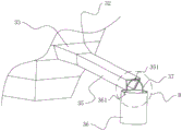
Referring to fig. 9, a hook 351 is arranged in the middle of the upper plate side of one end of the feeding pipe 35 far away from the connecting cylinder 33, the hook 351 is right-angled and perpendicular to the upper plate of the connecting cylinder 33, one end of the hook 351 is connected with the feeding pipe 35, and the other end of the hook extends upwards.
Referring to fig. 8, a receiving barrel 36 is hung on the shackle 351, and the receiving barrel 36 is a cylindrical barrel.
Referring to fig. 9, two symmetrical sides of the upper end of the receiving barrel 36 are respectively provided with a circular hole 361. The upper end of the receiving bucket 36 is provided with a hanging ring 37, two ends of the hanging ring 37 are bent towards the direction far away from the receiving bucket 36, two ends of the hanging ring 37 penetrate into the round holes 361, the hanging ring 37 is connected with the receiving bucket 36, and the receiving bucket 36 is used for receiving thicker particles.
Referring to fig. 10, two sides of the opening of the end of the feed delivery pipe 35 away from the connecting cylinder 33 are respectively provided with a striker plate 352, and the striker plates 352 are two rectangular baffles, are located at two ends of the inner side of the feed delivery pipe 35, have the same length as the two sides of the opening of the feed delivery pipe 35, and extend in the axial direction of the feed delivery pipe 35.
The implementation principle of the embodiment is as follows: smaller particles, larger particles and dust which come out of the ball mill main body 1 fall onto the screen 31 together, the smaller particles pass through the screen 31 and enter the conveying mechanism 2, the larger particles slide into the connecting cylinder 33 along the inclined screen 31, the baffle 34 blocks the dust flying along the larger particles, the larger particles enter the conveying pipe 35 from the lower part of the baffle 34 and then fall into the receiving barrel 36, when the very large particles pass through, the large particles impact the baffle 34, and the baffle 34 rotates to enable the large particles to pass through and enter the conveying pipe 35. The dust flying along with large particles can be prevented from entering the receiving barrel 36, and a large amount of dust in the recovered large particles is avoided.
The embodiment of this specific implementation mode is the preferred embodiment of the present invention, not limit according to this the utility model discloses a protection scope, so: all equivalent changes made according to the structure, shape and principle of the utility model are covered within the protection scope of the utility model.
Claims (8)
1. A discharge screening device of a ball mill comprises a ball mill main body (1) and a screening mechanism (3), wherein the screening mechanism (3) comprises a screen (31), the screen (31) is positioned at the upper end of a discharge pipe (11),
the method is characterized in that: the screening mechanism (3) further comprises a connecting cylinder (33), a material conveying port (32) and a baffle (34), and the ball mill main body (1) comprises a material discharging pipe (11);
the material conveying port (32) is positioned on the side wall of the ball mill main body (1);
the material conveying port (32) is connected with the connecting cylinder (33);
a baffle (34) is arranged in the connecting cylinder (33).
2. A ball mill discharge screening apparatus as set forth in claim 1, wherein: the upper end of the baffle (34) is rotatably connected with the connecting cylinder (33), and the rotating direction of the baffle (34) is parallel to the side wall of the connecting cylinder (33).
3. A ball mill discharge screening apparatus as set forth in claim 1, wherein: the included angles between the bottom plate of the connecting cylinder (33) and the two side walls are obtuse angles or arc-shaped.
4. A ball mill discharge screening apparatus as set forth in claim 2, wherein: the both sides limit of baffle (34) is laminated with two lateral walls of connecting cylinder (33) mutually, the last border of baffle (34) is laminated with the last roof of connecting cylinder (33).
5. A ball mill discharge screening apparatus as set forth in claim 1, wherein: the screen (31) is arranged obliquely in the direction of the connecting cylinder (33).
6. A ball mill discharge screening device as set forth in claim 5, wherein: the screen (31) is in a grid shape.
7. A ball mill discharge screening apparatus as set forth in claim 1, wherein: the direction that connecting cylinder (33) kept away from ball mill main part (1) sets up conveying pipeline (35), conveying pipeline (35) are to keeping away from the direction slope setting of connecting cylinder (33).
8. A ball mill discharge screening device as set forth in claim 7, wherein: the two sides of an opening in one end, away from the connecting cylinder (33), of the conveying pipe (35) are respectively provided with a material baffle plate (352), and the material baffle plates (352) are located at two ends of a bottom plate of the conveying pipe (35) and attached to two side walls of the conveying pipe (35).
Priority Applications (1)
| Application Number | Priority Date | Filing Date | Title |
|---|---|---|---|
| CN202021257062.8U CN212663746U (en) | 2020-06-30 | 2020-06-30 | Ball mill ejection of compact screening plant |
Applications Claiming Priority (1)
| Application Number | Priority Date | Filing Date | Title |
|---|---|---|---|
| CN202021257062.8U CN212663746U (en) | 2020-06-30 | 2020-06-30 | Ball mill ejection of compact screening plant |
Publications (1)
| Publication Number | Publication Date |
|---|---|
| CN212663746U true CN212663746U (en) | 2021-03-09 |
Family
ID=74819118
Family Applications (1)
| Application Number | Title | Priority Date | Filing Date |
|---|---|---|---|
| CN202021257062.8U Active CN212663746U (en) | 2020-06-30 | 2020-06-30 | Ball mill ejection of compact screening plant |
Country Status (1)
| Country | Link |
|---|---|
| CN (1) | CN212663746U (en) |
Cited By (1)
| Publication number | Priority date | Publication date | Assignee | Title |
|---|---|---|---|---|
| CN113019922A (en) * | 2021-03-26 | 2021-06-25 | 南召县长和实业有限公司 | Winnowing pretreatment device for coarse whiting micro powder |
-
2020
- 2020-06-30 CN CN202021257062.8U patent/CN212663746U/en active Active
Cited By (1)
| Publication number | Priority date | Publication date | Assignee | Title |
|---|---|---|---|---|
| CN113019922A (en) * | 2021-03-26 | 2021-06-25 | 南召县长和实业有限公司 | Winnowing pretreatment device for coarse whiting micro powder |
Similar Documents
| Publication | Publication Date | Title |
|---|---|---|
| CN105344448B (en) | Vegetable waste beats powder equipment | |
| CN208758077U (en) | Building waste dry-type separation system | |
| CN212663746U (en) | Ball mill ejection of compact screening plant | |
| US4240902A (en) | Apparatus for removing foreign matter from cotton | |
| CN111318967A (en) | Track passing type shot blasting machine for stone | |
| CN108160464B (en) | A kind of soil remediation gravity type soil screening plant | |
| CN110293063A (en) | A kind of aging garbage sorting system | |
| CN106076855B (en) | Rubbish automatic sorting complete set of equipments | |
| CN105618376B (en) | Building waste lightweight object sorts screening installation | |
| US3651621A (en) | Machine for extracting dirt from holes | |
| CN113909092B (en) | Rice processing edulcoration is with proportion destoner | |
| CN210701121U (en) | Concrete vibrates separation sieve | |
| CN209834734U (en) | Bucket elevator | |
| CN113578462B (en) | Calcium carbonate processing device for flame-retardant cable | |
| CN212733045U (en) | Sieving mechanism is used in corn processing | |
| CN212071626U (en) | Track passing type shot blasting machine for stone | |
| CN213474807U (en) | Feeding device with dust removal function | |
| KR102363599B1 (en) | Self-propelled poultry farm cleaner | |
| CN210235740U (en) | Storage box convenient to gather material | |
| CN218048046U (en) | Rice deep-processing is with collection mechanism of shelling equipment | |
| CN213230216U (en) | Rotary discharging device | |
| CN215587103U (en) | Dust device and rubble processing equipment | |
| CN220077954U (en) | Dustproof device of ash discharging vehicle | |
| CN212594643U (en) | Blanking device of dust remover | |
| CN210995284U (en) | Dust removal system for grain storage bin outlet |
Legal Events
| Date | Code | Title | Description |
|---|---|---|---|
| GR01 | Patent grant | ||
| GR01 | Patent grant |