CN212663522U - Energy-saving device of oxidation production device - Google Patents
Energy-saving device of oxidation production device Download PDFInfo
- Publication number
- CN212663522U CN212663522U CN202020660014.7U CN202020660014U CN212663522U CN 212663522 U CN212663522 U CN 212663522U CN 202020660014 U CN202020660014 U CN 202020660014U CN 212663522 U CN212663522 U CN 212663522U
- Authority
- CN
- China
- Prior art keywords
- oxidation
- pipe
- oxidation chamber
- heating
- energy
- Prior art date
- Legal status (The legal status is an assumption and is not a legal conclusion. Google has not performed a legal analysis and makes no representation as to the accuracy of the status listed.)
- Active
Links
Images

Landscapes
- Physical Or Chemical Processes And Apparatus (AREA)
Abstract
The utility model discloses an economizer of oxidation apparatus for producing, including oxidation chamber and economizer, outer box is installed in the outside of oxidation chamber, and the internally mounted of oxidation chamber has mixing mechanism, the below of oxidation chamber is provided with the discharge gate, and the top front and back side of oxidation chamber is provided with the charge door, economizer sets up in the inboard of oxidation chamber, economizer's inboard is provided with the zone of heating, and the internally mounted of zone of heating has the heating rod, the polar plate is installed to the inboard of zone of heating. This oxidation apparatus for producing's economizer passes through the rotation that motor and drive shaft are convenient for drive rotation axis and stirring leaf to in improving the mixing degree of oxidation indoor oxidation product and oxygen, make it fully react with oxygen, improve oxidation efficiency, constitute linkage structure through driving belt between the drive shaft and make a set of driving motor of two oxidation rooms sharing, have energy-conserving effect equally.
Description
Technical Field
The utility model relates to an oxidation apparatus for producing technical field specifically is an economizer of oxidation apparatus for producing.
Background
Oxidation production, also known as oxidation or oxidation reaction, is required during the use of the oxidation apparatus. An oxidation reaction is a chemical reaction of a substance with oxygen. When the organic matter reacts, the action of introducing oxygen into the organic matter or removing hydrogen is called oxidation; the introduction of hydrogen or the loss of oxygen is called reduction.
The existing oxidation production device cannot fully mix materials in the reaction process, so that the reaction efficiency is low, waste heat recovery cannot be performed in the reaction process, energy is saved, consumption is high, energy-saving production is not facilitated, and therefore the energy-saving device of the oxidation production device is provided.
SUMMERY OF THE UTILITY MODEL
An object of the utility model is to provide an oxidation apparatus for producing to solve the current oxidation apparatus for producing who proposes in the above-mentioned background art and can not carry out the intensive mixing to the material in reaction process, consequently reaction efficiency is lower, and can not carry out waste heat recovery and then save energy at reaction process, make to consume higher, be unfavorable for the problem of energy-conserving production.
In order to achieve the above object, the utility model provides a following technical scheme: the utility model provides an energy-saving device of oxidation apparatus for producing, includes oxidation chamber and economizer, outer box is installed in the outside of oxidation chamber, and the internally mounted of oxidation chamber has mixing mechanism, the below of oxidation chamber is provided with the discharge gate, and the top front and back side of oxidation chamber is provided with the charge door, economizer sets up in the inboard of oxidation chamber, economizer's inboard is provided with the zone of heating, and the internally mounted of zone of heating has the heating rod, the polar plate is installed to the inboard of zone of heating.
Preferably, state mixing mechanism including motor, drive shaft, rotation axis, stirring leaf and driving belt, the motor is installed to the middle part top of oxidation chamber, and the downside of motor is provided with the drive shaft, the downside of drive shaft is connected with the rotation axis, and the outside of rotation axis is fixed with the stirring leaf, be provided with driving belt between the drive shaft.
Preferably, the rotating shaft and the stirring blades form a rotating structure through a driving shaft, and a linkage structure is formed between the driving shafts through a transmission belt.
Preferably, energy-conserving mechanism is including heat preservation, surrounding pipe, exhaust pipe, filter screen, connecting pipe and drain pipe, the inboard of oxidizing chamber is provided with the heat preservation, and the internally mounted of heat preservation has the surrounding pipe, top one side of oxidizing chamber is provided with the exhaust pipe, and the inside of exhaust pipe is fixed with the filter screen, the outside of exhaust pipe is fixed with the connecting pipe, and the other end of connecting pipe links to each other with the upper end of surrounding pipe, the bottom one end of surrounding pipe is connected with the drain pipe.
Preferably, the surrounding pipe is in a circulating U shape and surrounds the inner part of the heat insulation layer, and the symmetric center of the surrounding pipe is coincided with the symmetric center of the oxidation chamber.
Preferably, the steam exhaust pipe is communicated with the interior of the surrounding pipe through a connecting pipe, and the connecting pipe is fixedly connected with the surrounding pipe.
Preferably, a concentric circle mode is formed between the heating layer and the oxidation chamber, and heating rods are symmetrically and uniformly distributed in the heating layer.
Compared with the prior art, the beneficial effects of the utility model are that: the energy-saving device of the oxidation production device is provided with an outer box body which is positioned outside the oxidation chamber and can protect the oxidation chamber, heating rods which are uniformly distributed inside a heating layer are convenient for heating the inside of the oxidation chamber so as to facilitate the oxidation production inside the oxidation chamber, and the inside of the oxidation chamber can be subjected to electrolytic catalysis to promote the oxidation reaction through a polar plate;
the rotation of the rotating shaft and the stirring blades is conveniently driven by the motor and the driving shaft, so that the mixing degree of the oxidation products and the oxygen in the oxidation chambers is improved, the oxidation products and the oxygen are fully reacted, the oxidation efficiency is improved, a linkage structure is formed between the driving shafts through a transmission belt, so that the two oxidation chambers can share one group of driving motors, and the energy-saving effect is also achieved;
the feed liquid of the inside high temperature vaporization of oxidation chamber can transpire and rise and lead into to the inside of surrounding pipe through the connecting pipe, and the center of symmetry of surrounding pipe and oxidation chamber coincide for surround the inside of pipe and surround the oxidation chamber and heat at the oxidation chamber inside, play waste heat recovery and utilize's effect, thereby be convenient for energy-conservation.
Drawings
FIG. 1 is a schematic front view of the present invention;
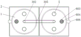
FIG. 2 is a schematic top view of the present invention;
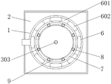
fig. 3 is a schematic view of the inside cross-section structure of the oxidation chamber of the present invention.
In the figure: 1. an oxidation chamber; 2. an outer case; 3. a mixing mechanism; 301. a motor; 302. a drive shaft; 303. a rotating shaft; 304. stirring blades; 305. a drive belt; 4. a discharge port; 5. a feed inlet; 6. an energy-saving mechanism; 601. a heat-insulating layer; 602. a surrounding tube; 603. a steam exhaust pipe; 604. a filter screen; 605. a connecting pipe; 606. a drain pipe; 7. a heating layer; 8. a heating rod; 9. and (4) a polar plate.
Detailed Description
The technical solutions in the embodiments of the present invention will be described clearly and completely with reference to the accompanying drawings in the embodiments of the present invention, and it is obvious that the described embodiments are only some embodiments of the present invention, not all embodiments. Based on the embodiments in the present invention, all other embodiments obtained by a person skilled in the art without creative work belong to the protection scope of the present invention.
Referring to fig. 1-3, the present invention provides a technical solution: an energy-saving device of an oxidation production device comprises an oxidation chamber 1, an outer box body 2, a mixing mechanism 3, a motor 301, a driving shaft 302, a rotating shaft 303, a stirring blade 304, a transmission belt 305, a discharge port 4, a charging port 5, an energy-saving mechanism 6, a heat-insulating layer 601, a surrounding pipe 602, an exhaust pipe 603, a filter screen 604, a connecting pipe 605, a drain pipe 606, a heating layer 7, a heating rod 8 and a polar plate 9, wherein the outer box body 2 is arranged outside the oxidation chamber 1, the mixing mechanism 3 is arranged inside the oxidation chamber 1, the mixing mechanism 3 comprises the motor 301, the driving shaft 302, the rotating shaft 303, the stirring blade 304 and the transmission belt 305, the motor 301 is arranged above the middle part of the oxidation chamber 1, the driving shaft 302 is arranged on the lower side of the motor 301, the rotating shaft 303 is connected on the lower side of the driving shaft 302, the stirring blade 304 is, the rotating shaft 303 and the stirring blades 304 form a rotating structure through the driving shaft 302, a linkage structure is formed between the driving shafts 302 through the transmission belt 305, the rotating shaft 303 and the stirring blades 304 are conveniently driven to rotate through the motor 301 and the driving shaft 302, so that the mixing degree of the oxidation product and the oxygen in the oxidation chamber 1 is improved, the oxidation product and the oxygen are fully reacted, and the oxidation efficiency is improved;
the lower part of the oxidation chamber 1 is provided with a discharge port 4, the front side and the rear side of the upper part of the oxidation chamber 1 are provided with feed inlets 5, the energy-saving mechanism 6 is arranged at the inner side of the oxidation chamber 1, the energy-saving mechanism 6 comprises a heat-insulating layer 601, a surrounding pipe 602, a steam exhaust pipe 603, a filter screen 604, a connecting pipe 605 and a water drain pipe 606, the heat-insulating layer 601 is arranged at the inner side of the oxidation chamber 1, and the surrounding pipe 602 is arranged in the heat-insulating layer 601. A steam exhaust pipe 603 is arranged at one side above the oxidation chamber 1, a filter screen 604 is fixed in the steam exhaust pipe 603, a connecting pipe 605 is fixed at the outer side of the steam exhaust pipe 603, and the other end of the connecting pipe 605 is connected to the upper end of the surrounding pipe 602, one end of the bottom of the surrounding pipe 602 is connected to a drain pipe 606, the surrounding pipe 602 surrounds the inside of the insulating layer 601 in a circulating "U" shape, and the symmetric center of the surrounding pipe 602 coincides with the symmetric center of the oxidation chamber 1, the surrounding pipe 602 is arranged to facilitate heating the inside of the oxidation chamber 1, thereby playing a role of waste heat recovery, thereby facilitating energy saving, the exhaust pipe 603 is communicated with the inside of the surrounding pipe 602 through the connection pipe 605, and the connection pipe 605 is fixedly connected with the surrounding pipe 602, the material liquid vaporized at high temperature in the oxidation chamber 1 can be introduced into the surrounding pipe 602 by rising through the connecting pipe 605, and the oxidation chamber 1 is heated;
the inboard of economizer mechanism 6 is provided with zone of heating 7, and the internally mounted of zone of heating 7 has heating rod 8, is the concentric circles mode between zone of heating 7 and the oxidation chamber 1, and the inside of zone of heating 7 is symmetry form evenly distributed and has heating rod 8, and the inside evenly distributed's of zone of heating 7 heating rod 8 is convenient for heat the inside of oxidation chamber 1 to in the oxidation production of oxidation chamber 1 inside, polar plate 9 is installed to the inboard of zone of heating 7.
The working principle is as follows: the energy-saving device for the oxidation production device can firstly introduce catalyst and oxidation products through two feed inlets 5 above the oxidation chamber 1, and introduce oxygen, then heat the interior of the oxidation chamber 1 through heating rods 8 uniformly distributed in a heating layer 7, at the same time, promote oxidation reaction through electrolytic catalysis of a polar plate 9 to the interior of the oxidation chamber 1, and then start the motor 301, so that the motor 301 and the driving shaft 302 drive the rotation of the rotating shaft 303 and the stirring blades 304, so as to improve the mixing degree of the oxidation products and the oxygen in the oxidation chamber 1, fully react with the oxygen, and improve the oxidation efficiency, in the process, feed liquid vaporized at high temperature in the oxidation chamber 1 can be transpired and lifted to be led into the surrounding pipe 602 through the connecting pipe 605, so that the surrounding pipe 602 surrounds the inner side of the oxidation chamber 1 to heat the interior of the oxidation chamber 1, the effect of waste heat recovery and utilization is achieved, energy is saved, finally, condensed liquid in the surrounding pipe 602 can pass through the drain pipe 606, after the reaction is completed, the discharge hole 4 is opened, and reactants are discharged, so that the using process of the energy-saving device of the whole oxidation production device is completed.
Although embodiments of the present invention have been shown and described, it will be appreciated by those skilled in the art that changes, modifications, substitutions and alterations can be made in these embodiments without departing from the principles and spirit of the invention, the scope of which is defined in the appended claims and their equivalents.
Claims (7)
1. An energy-saving device of an oxidation production device comprises an oxidation chamber (1) and an energy-saving mechanism (6), and is characterized in that: outer box body (2) are installed in the outside of oxidation chamber (1), and the internally mounted of oxidation chamber (1) has mixing mechanism (3), the below of oxidation chamber (1) is provided with discharge gate (4), and the top front and back side of oxidation chamber (1) is provided with charge door (5), energy-conserving mechanism (6) set up in the inboard of oxidation chamber (1), the inboard of energy-conserving mechanism (6) is provided with zone of heating (7), and the internally mounted of zone of heating (7) has heating rod (8), polar plate (9) are installed to the inboard of zone of heating (7).
2. An energy saving device of an oxidation production apparatus according to claim 1, wherein: mixing mechanism (3) is including motor (301), drive shaft (302), rotation axis (303), stirring leaf (304) and driving belt (305), motor (301) are installed to the middle part top of oxidation chamber (1), and the downside of motor (301) is provided with drive shaft (302), the downside of drive shaft (302) is connected with rotation axis (303), and the outside of rotation axis (303) is fixed with stirring leaf (304), be provided with driving belt (305) between drive shaft (302).
3. An energy saving device of an oxidation production apparatus according to claim 2, wherein: the rotating shaft (303) and the stirring blades (304) form a rotating structure through a driving shaft (302), and a linkage structure is formed between the driving shafts (302) through a transmission belt (305).
4. An energy saving device of an oxidation production apparatus according to claim 1, wherein: energy-conserving mechanism (6) are including heat preservation (601), encircle pipe (602), exhaust pipe (603), filter screen (604), connecting pipe (605) and drain pipe (606), the inboard of oxidation chamber (1) is provided with heat preservation (601), and the internally mounted of heat preservation (601) has surrounding pipe (602), top one side of oxidation chamber (1) is provided with exhaust pipe (603), and the inside of exhaust pipe (603) is fixed with filter screen (604), the outside of exhaust pipe (603) is fixed with connecting pipe (605), and the other end of connecting pipe (605) links to each other with the upper end of surrounding pipe (602), the bottom one end of surrounding pipe (602) is connected with drain pipe (606).
5. An energy saving device of an oxidation production apparatus according to claim 4, wherein: the surrounding pipe (602) is circularly U-shaped and surrounds the inside of the heat insulation layer (601), and the symmetry center of the surrounding pipe (602) is superposed with the symmetry center of the oxidation chamber (1).
6. An energy saving device of an oxidation production apparatus according to claim 4, wherein: the steam exhaust pipe (603) is communicated with the interior of the surrounding pipe (602) through a connecting pipe (605), and the connecting pipe (605) is fixedly connected with the surrounding pipe (602).
7. An energy saving device of an oxidation production apparatus according to claim 1, wherein: the heating layer (7) and the oxidation chamber (1) are in a concentric circle mode, and heating rods (8) are symmetrically and uniformly distributed in the heating layer (7).
Priority Applications (1)
| Application Number | Priority Date | Filing Date | Title |
|---|---|---|---|
| CN202020660014.7U CN212663522U (en) | 2020-04-27 | 2020-04-27 | Energy-saving device of oxidation production device |
Applications Claiming Priority (1)
| Application Number | Priority Date | Filing Date | Title |
|---|---|---|---|
| CN202020660014.7U CN212663522U (en) | 2020-04-27 | 2020-04-27 | Energy-saving device of oxidation production device |
Publications (1)
| Publication Number | Publication Date |
|---|---|
| CN212663522U true CN212663522U (en) | 2021-03-09 |
Family
ID=74815330
Family Applications (1)
| Application Number | Title | Priority Date | Filing Date |
|---|---|---|---|
| CN202020660014.7U Active CN212663522U (en) | 2020-04-27 | 2020-04-27 | Energy-saving device of oxidation production device |
Country Status (1)
| Country | Link |
|---|---|
| CN (1) | CN212663522U (en) |
Cited By (3)
| Publication number | Priority date | Publication date | Assignee | Title |
|---|---|---|---|---|
| CN113800554A (en) * | 2021-09-16 | 2021-12-17 | 安徽骏马新材料科技股份有限公司 | Energy-saving powder making furnace of bus |
| CN114177856A (en) * | 2021-12-09 | 2022-03-15 | 安徽骏马新材料科技股份有限公司 | Red lead production facility of environmental protection |
| CN116173838A (en) * | 2022-12-31 | 2023-05-30 | 江苏道明化学有限公司 | Continuous reduction device for producing dicumyl hydroperoxide |
-
2020
- 2020-04-27 CN CN202020660014.7U patent/CN212663522U/en active Active
Cited By (5)
| Publication number | Priority date | Publication date | Assignee | Title |
|---|---|---|---|---|
| CN113800554A (en) * | 2021-09-16 | 2021-12-17 | 安徽骏马新材料科技股份有限公司 | Energy-saving powder making furnace of bus |
| CN113800554B (en) * | 2021-09-16 | 2023-05-02 | 安徽骏马新材料科技股份有限公司 | Energy-saving pulverizing furnace of Baji |
| CN114177856A (en) * | 2021-12-09 | 2022-03-15 | 安徽骏马新材料科技股份有限公司 | Red lead production facility of environmental protection |
| CN116173838A (en) * | 2022-12-31 | 2023-05-30 | 江苏道明化学有限公司 | Continuous reduction device for producing dicumyl hydroperoxide |
| CN116173838B (en) * | 2022-12-31 | 2023-09-15 | 江苏道明化学有限公司 | Continuous reduction device for producing dicumyl hydroperoxide |
Similar Documents
| Publication | Publication Date | Title |
|---|---|---|
| CN212663522U (en) | Energy-saving device of oxidation production device | |
| WO2017096657A1 (en) | Apparatus for dry anaerobic fermentation of dewatered sludge | |
| CN113714245A (en) | Kitchen waste treatment device, waste treatment system and treatment method | |
| CN211770891U (en) | Sludge treatment device | |
| CN116336769A (en) | High-purity manganese sulfate crystallization drying system | |
| CN216064828U (en) | Multi-bin type high-energy-saving garbage deodorization equipment | |
| CN210279155U (en) | Reaction tank capable of efficiently transferring heat | |
| CN213708381U (en) | High-strength salt-resistant embedding bacterium production device | |
| CN214106904U (en) | Stainless steel retort is used in dipotassium hydrogen phosphate production | |
| CN106669576A (en) | Sufficient stirring Co(OH)2 preparation device | |
| CN217856096U (en) | Reaction kettle with heating and cooling functions for producing polyamino acid | |
| CN217973115U (en) | A fermenting installation for yellow rice wine processing | |
| CN210965078U (en) | High-efficient green's compound carbon source for replenisher that contains sodium acetate | |
| CN220317740U (en) | Wine making machine for black ginseng wine preparation | |
| CN221217691U (en) | Integrative device of microorganism fungus fertilizer reaction fermentation stoving | |
| CN220467585U (en) | Carbonization material activation device for activated carbon production | |
| CN214599064U (en) | A energy-conserving apparatus for producing aluminium triphosphate | |
| CN214892366U (en) | Energy-saving fermented feed drying device | |
| CN118274599B (en) | Drying equipment for lithium salt particles | |
| CN211998874U (en) | Novel high-efficient environmental protection waste water waste gas complete sets treatment facility | |
| CN220796343U (en) | Energy-saving and environment-friendly low-temperature silver paste production device | |
| CN212283983U (en) | Heat preservation type polymerization cauldron is used in polyacrylamide production | |
| CN109081355B (en) | Portable fuel cell automobile power supply equipment | |
| CN220803255U (en) | Maleimide agitated vessel | |
| CN216799775U (en) | Temperature control system of carboxylation reaction kettle |
Legal Events
| Date | Code | Title | Description |
|---|---|---|---|
| GR01 | Patent grant | ||
| GR01 | Patent grant |