CN212655160U - Automatic blending device is used in production of high temperature wear-resisting coating - Google Patents
Automatic blending device is used in production of high temperature wear-resisting coating Download PDFInfo
- Publication number
- CN212655160U CN212655160U CN202021118158.6U CN202021118158U CN212655160U CN 212655160 U CN212655160 U CN 212655160U CN 202021118158 U CN202021118158 U CN 202021118158U CN 212655160 U CN212655160 U CN 212655160U
- Authority
- CN
- China
- Prior art keywords
- feeding barrel
- collecting bin
- material collecting
- temperature wear
- production
- Prior art date
- Legal status (The legal status is an assumption and is not a legal conclusion. Google has not performed a legal analysis and makes no representation as to the accuracy of the status listed.)
- Active
Links
Images

Abstract
The utility model discloses an automatic batching device for producing high-temperature wear-resistant paint, which relates to the field of automatic batching systems and comprises a material collecting bin, wherein a plurality of loading hoppers with weight sensors are hinged on the outer edge of the top of the material collecting bin, the hinged parts of the loading hoppers and the material collecting bin are connected with a motor I, and the motor I drives the loading hoppers to turn towards the inner direction of the material collecting bin; a feeding barrel which is horizontally arranged is arranged above each charging hopper respectively, a rotating shaft is coaxially arranged in each feeding barrel, a spiral blade is arranged on each rotating shaft, a plurality of bulges are arranged on the inner wall of each feeding barrel, a space is reserved between each bulge and the spiral blade, the rotating shaft is driven by a motor II arranged at one end of a barrel body, a discharging port is formed in the bottom of the other end of each feeding barrel, and the discharging port is positioned right above the corresponding charging hopper; and a storage tank is respectively arranged at the top of one end of each feeding barrel, which is far away from the discharge port. The utility model discloses effectively solved traditional production batching process batching wasting of resources serious, the easy caking of raw materials is difficult for taking out the scheduling problem in the storage tank.
Description
Technical Field
The utility model relates to an automatic blending system field, concretely relates to automatic blending device is used in production of high temperature wear-resisting coating.
Background
The high-temperature wear-resistant coating is a material formed by mixing a plurality of components, and the mixture ratio of various raw materials needs to be set when the product is produced in a mixing way, wherein the performance of the final product can be influenced by more or less amount of any raw material.
At present, the production process of most of small and medium-sized enterprises depends on manual means to carry out batching and batching management, batching personnel manually calculate the weight of each raw material according to a batching list and select proper containers and weighing equipment to carry out batching. The batching mode has the problems of uneven product quality, high precision control difficulty, low working efficiency, complicated and unordered production procedures, disordered batching process record management, serious batching resource waste and the like; in addition, when the raw materials of the high-temperature wear-resistant coating are stored, the raw materials can be caked in the material storage tank, so that the subsequent proportioning production process is influenced.
Disclosure of Invention
An object of the utility model is to overcome the not enough of above-mentioned technique, provide an automatic blending device is used in production of high temperature wear-resisting coating, realize the accurate control and the high-efficient management of high temperature wear-resisting coating batching process, solved traditional production batching process batching wasting of resources seriously, raw materials easily agglomerate difficult scheduling problem of taking out in the storage tank.
In order to realize the purpose of the utility model, the utility model adopts the technical scheme that: the automatic batching device for producing the high-temperature wear-resistant paint is characterized by comprising a material collecting bin, wherein a plurality of charging hoppers with weight sensors are hinged to the outer edge of the top of the material collecting bin, motors I are connected to hinged positions of the charging hoppers and the material collecting bin, and the motors I drive the charging hoppers to turn towards the inner direction of the material collecting bin; a feeding barrel which is horizontally arranged is arranged above each charging hopper respectively, a rotating shaft is coaxially arranged in the feeding barrel, a spiral blade is arranged on the rotating shaft, a plurality of bulges are arranged on the inner wall of the feeding barrel, a space is reserved between each bulge and the spiral blade, the rotating shaft is driven by a motor II arranged at one end of a barrel body, a discharging port is formed in the bottom of the other end of the feeding barrel, and the discharging port is positioned right above the corresponding charging hopper; and the top of one end of each feeding barrel, which is far away from the discharge port, is respectively provided with a storage tank, and different product raw materials are stored in each storage tank.
Further, each feeding barrel is fixedly supported through a support.
Further, the charging hoppers are uniformly distributed at intervals along the outer edge of the top of the aggregate bin.
Furthermore, the aggregate bin is of a conical structure with a large upper part and a small lower part, so that the raw materials can be conveniently collected.
Furthermore, the outer wall of the aggregate bin is provided with a vibrator which vibrates the raw material powder attached to the inner wall of the aggregate bin to the bottom of the aggregate bin.
Furthermore, a plurality of supporting platforms extend outwards and horizontally from the outer edge of the top of the material collecting bin, the charging hoppers are arranged on the supporting platforms respectively, and the motors I are also fixed on the supporting platforms.
The utility model has the advantages that: this device sends different raw materials to each pay-off section of thick bamboo in through each storage tank, extrudees the breakage each other in the arch of helical blade and section of thick bamboo wall, with the bold caking raw materials breakage and carry to drop on each charging hopper, accurate measurement under weighing transducer's effect, after obtaining the raw materials of required weight, each pay-off section of thick bamboo stops carrying, and each charging hopper is around the pin joint upset, with the raw materials drop into the storehouse that gathers materials in, the accurate of accomplishing product raw materials is weighed and is carried, accomplishes the batching. This device simple structure has effectively solved traditional production batching process batching wasting of resources seriously, the easy difficult scheduling problem that takes out of caking of raw materials in the storage tank.
Drawings
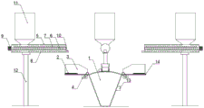
Fig. 1 is a front view of the present invention.
Fig. 2 is a top view of the present invention.
In the figure: aggregate bin 1, weight sensor 2, charging hopper 3, motor I4, feed cylinder 5, pivot 6, helical blade 7, arch 8, motor II 9, discharge gate 10, storage tank 11, support 12, vibrator 13, supporting platform 14.
Detailed Description
The technical solution in the embodiments of the present invention will be clearly and completely described below with reference to the accompanying drawings.
Example 1
As shown in fig. 1-2, an automatic batching device for producing high-temperature wear-resistant paint comprises a collecting bin 1, wherein a plurality of loading hoppers 3 with weight sensors 2 are hinged to the outer edge of the top of the collecting bin 1, motors I4 are connected to the hinged positions of the loading hoppers 3 and the collecting bin 1, and the motors I4 drive the loading hoppers 3 to turn towards the inner direction of the collecting bin 1; a feeding barrel 5 which is horizontally arranged is arranged above each charging hopper 3, a rotating shaft 6 is coaxially arranged in each feeding barrel 5, a helical blade 7 is arranged on each rotating shaft 6, a plurality of protrusions 8 are arranged on the inner wall of each feeding barrel 5, a space is reserved between each protrusion 8 and each helical blade 7, each rotating shaft 6 is driven by a motor II 9 arranged at one end of a barrel body, a discharging port 10 is formed in the bottom of the other end of each feeding barrel 5, and each discharging port 10 is located right above the corresponding charging hopper 3; the top of one end of each feeding barrel 5, which is far away from the discharge port 10, is respectively provided with a storage tank 11, and different product raw materials are stored in each storage tank 11; each feeding barrel 5 is fixedly supported by a bracket 12; the charging hoppers 3 are uniformly distributed at intervals along the outer edge of the top of the aggregate bin 1; the material collecting bin 1 is of a conical structure with a large upper part and a small lower part, so that the raw materials can be conveniently collected; the vibrator 13 is arranged on the outer wall of the material collecting bin 1 and vibrates the raw material powder attached to the inner wall of the material collecting bin 1 to the bottom of the material collecting bin 1; a plurality of supporting platforms 14 extend outwards and horizontally from the outer edge of the top of the collecting bin 1, each charging hopper 3 is arranged on each supporting platform 14, and each motor I4 is also fixed on each supporting platform 14.
The described embodiments are only some, but not all embodiments of the invention. Based on the embodiments in the present invention, all other embodiments obtained by a person skilled in the art without creative work belong to the protection scope of the present invention.
Claims (6)
1. The automatic batching device for producing the high-temperature wear-resistant paint is characterized by comprising a material collecting bin, wherein a plurality of charging hoppers with weight sensors are hinged to the outer edge of the top of the material collecting bin, motors I are connected to hinged positions of the charging hoppers and the material collecting bin, and the motors I drive the charging hoppers to turn towards the inner direction of the material collecting bin; a feeding barrel which is horizontally arranged is arranged above each charging hopper respectively, a rotating shaft is coaxially arranged in the feeding barrel, a spiral blade is arranged on the rotating shaft, a plurality of bulges are arranged on the inner wall of the feeding barrel, a space is reserved between each bulge and the spiral blade, the rotating shaft is driven by a motor II arranged at one end of a barrel body, a discharging port is formed in the bottom of the other end of the feeding barrel, and the discharging port is positioned right above the corresponding charging hopper; and the top of one end of each feeding barrel, which is far away from the discharge port, is respectively provided with a storage tank, and different product raw materials are stored in each storage tank.
2. The automatic batching device for the production of the high-temperature wear-resistant coating according to claim 1, wherein each feeding cylinder is fixedly supported by a bracket.
3. The automatic batching device for the production of the high-temperature wear-resistant coating according to claim 1, wherein the charging hoppers are uniformly distributed at intervals along the top outer edge of the aggregate bin.
4. The automatic batching device for the production of the high-temperature wear-resistant paint as claimed in claim 1, wherein the aggregate bin is of a conical structure with a large upper part and a small lower part.
5. The automatic batching device for the production of the high-temperature wear-resistant paint as claimed in claim 1, wherein a vibrator is mounted on the outer wall of the aggregate bin.
6. The automatic batching device for the production of the high-temperature wear-resistant coating according to claim 1, wherein a plurality of supporting platforms horizontally extend outwards from the outer edge of the top of the collecting bin, each charging hopper is respectively arranged on each supporting platform, and each motor I is also fixed on each supporting platform.
Priority Applications (1)
| Application Number | Priority Date | Filing Date | Title |
|---|---|---|---|
| CN202021118158.6U CN212655160U (en) | 2020-06-17 | 2020-06-17 | Automatic blending device is used in production of high temperature wear-resisting coating |
Applications Claiming Priority (1)
| Application Number | Priority Date | Filing Date | Title |
|---|---|---|---|
| CN202021118158.6U CN212655160U (en) | 2020-06-17 | 2020-06-17 | Automatic blending device is used in production of high temperature wear-resisting coating |
Publications (1)
| Publication Number | Publication Date |
|---|---|
| CN212655160U true CN212655160U (en) | 2021-03-05 |
Family
ID=74752967
Family Applications (1)
| Application Number | Title | Priority Date | Filing Date |
|---|---|---|---|
| CN202021118158.6U Active CN212655160U (en) | 2020-06-17 | 2020-06-17 | Automatic blending device is used in production of high temperature wear-resisting coating |
Country Status (1)
| Country | Link |
|---|---|
| CN (1) | CN212655160U (en) |
-
2020
- 2020-06-17 CN CN202021118158.6U patent/CN212655160U/en active Active
Similar Documents
| Publication | Publication Date | Title |
|---|---|---|
| CN201998342U (en) | Device for mixing raw material | |
| CN205419147U (en) | Constant volume volume feeding device | |
| CN206262397U (en) | A kind of many raw material mixed food burdening systems | |
| CN214863306U (en) | Multi-component weighing type mixing equipment | |
| CN206345029U (en) | A kind of automatic feeder | |
| CN206013924U (en) | A kind of fermentation tank feed arrangement | |
| CN205707424U (en) | The ration package scale of automatic charging | |
| CN212655160U (en) | Automatic blending device is used in production of high temperature wear-resisting coating | |
| CN206676317U (en) | A kind of Chemical Manufacture enclosed material automatic blending system | |
| CN207401389U (en) | Feed mix station | |
| CN204154366U (en) | The continuous decrement Weighing device of a kind of nickel minerals powder | |
| CN209871794U (en) | Automatic continuous feeding system | |
| CN212915540U (en) | Automatic blending and mixing device for production of high-temperature wear-resistant paint | |
| CN207533123U (en) | A kind of Feed Manufacturing automatic blending hybrid system | |
| CN214082145U (en) | Powder feeding device of concrete mixing plant | |
| CN215638727U (en) | Prevent hanging material homogenization storehouse rotor scale material feeding unit | |
| CN203349908U (en) | Material suction type conveying belt weighing machine | |
| CN211310171U (en) | Efficient, environment-friendly and energy-saving dry powder mortar production line | |
| CN210504783U (en) | Feeding device and urea machine | |
| CN210148421U (en) | Concrete proportioning machine | |
| CN209956980U (en) | Full-automatic auxiliary agent batching system | |
| CN209064447U (en) | It is anti-sticking glutinous without extruding brown sugar quantitative racking machine | |
| CN208716448U (en) | A kind of feedstock transportation feed system of achievable static weighing | |
| CN208732169U (en) | A kind of anti-layered quantitative charging gear | |
| CN209715041U (en) | A kind of porous crucible proportioner |
Legal Events
| Date | Code | Title | Description |
|---|---|---|---|
| GR01 | Patent grant | ||
| GR01 | Patent grant |