CN212609155U - Rotary suspension arm device of steel reinforcement cage - Google Patents
Rotary suspension arm device of steel reinforcement cage Download PDFInfo
- Publication number
- CN212609155U CN212609155U CN202021301686.5U CN202021301686U CN212609155U CN 212609155 U CN212609155 U CN 212609155U CN 202021301686 U CN202021301686 U CN 202021301686U CN 212609155 U CN212609155 U CN 212609155U
- Authority
- CN
- China
- Prior art keywords
- arm
- lifting
- reinforcement cage
- steel reinforcement
- steel
- Prior art date
- Legal status (The legal status is an assumption and is not a legal conclusion. Google has not performed a legal analysis and makes no representation as to the accuracy of the status listed.)
- Active
Links
Images


Abstract
The utility model discloses a rotatory davit device of steel reinforcement cage, include: the steel bar cage lifting device comprises a support column fixed on a factory building, a lifting arm rotationally connected to the stand column, a connecting arm with one end rotationally connected to the stand column and the other end connected to the lifting arm, a supporting arm connected between the connecting arm and the lifting arm, a lifting mechanism fixed below the lifting arm and driving the steel bar cage to move in the left-right direction, a traction rope connected to the lifting mechanism and sliding on the lifting mechanism, lifting ropes connected to two ends of the traction rope, and hooks arranged on the lifting ropes; workers can easily use the remote controller to complete the rotation of the steel reinforcement cage, and two lifting points at the lifting end of the steel reinforcement cage are uniformly stressed, so that the deformation of the steel reinforcement cage is avoided, the efficiency is high, and the production quality is high; the materials of the suspension arm, the connecting arm and the supporting arm are selected, so that the suspension arm is large in bearing capacity, light in self weight, economical and durable.
Description
Technical Field
The utility model relates to a steel reinforcement cage spin welding production instrument field, especially a steel reinforcement cage rotatory davit device.
Background
The rail transit construction is a mark of the urban economic development scale and the social civilization degree, and with the continuous progress and development of the shield technology, the shield construction is generally applied to the construction of urban subways at present.
The underground part of the track traffic is constructed by adopting a shield method, the progress is fast, the required quantity of duct pieces on a construction site is large, and in order to meet the requirement of site construction, the requirement of improving the yield of the duct pieces can be met by improving the yield, the quality and other work of semi-finished duct piece reinforcement cages.
However, as the truss vehicle is used for overturning the duct pieces in the steel bar workshop, a plurality of stations are in a waiting state, so that the efficiency is low, the production efficiency of the duct pieces is seriously influenced, and the production pressure of a duct piece factory is increased; market needs one kind can make things convenient for the workman to operate, easily realizes the rotatory steel reinforcement cage rotary device of steel reinforcement cage, the utility model provides a such problem.
SUMMERY OF THE UTILITY MODEL
For solving prior art's not enough, the utility model aims to provide a rotatory davit device of steel reinforcement cage, through using this device, the workman can accomplish the steel reinforcement cage rotation through the remote controller operation, and the steel reinforcement cage lifts by crane two hoisting points atress of end even, avoids the steel reinforcement cage to warp, and is not only high-efficient, production quality is high moreover.
In order to achieve the above object, the utility model adopts the following technical scheme:
rotatory davit device of steel reinforcement cage includes: the lifting mechanism is fixed below the lifting arm and drives the steel reinforcement cage to move in the left-right direction, the hauling rope is connected to the lifting mechanism and slides in the lifting mechanism, the lifting ropes are connected to two ends of the hauling rope, and the hooks are arranged on the lifting ropes.
In the rotating suspension arm device for the steel reinforcement cage, the support is an I-shaped steel support.
According to the rotary suspension arm device for the steel reinforcement cage, the suspension arm is an I-shaped steel suspension arm.
In the rotating suspension arm device for the steel reinforcement cage, the connecting arm is a square pipe steel connecting arm.
According to the rotary suspension arm device for the steel reinforcement cage, the support arm is a square tube steel support arm.
According to the rotating suspension arm device of the steel reinforcement cage, the suspension arm and the stand column are anchored through the articulated piece, and the connecting arm and the stand column are anchored through the articulated piece.
According to the rotary lifting arm device for the steel reinforcement cage, the lifting mechanism is an electric hoist.
The utility model discloses an useful part lies in:
workers can complete the rotation of the reinforcement cage through the operation of a remote controller, and the operation is simple and efficient;
the supporting columns and the suspension arms are made of I-shaped steel, and the connecting arms and the supporting arms are made of square tube steel, so that the design ensures that the suspension arms are large in bearing capacity, light in self weight, economical and durable;
through the rotation of the suspension arm and the left-right movement of the electric hoist, two suspension points at the lifting end of the steel reinforcement cage are uniformly stressed, the deformation of the steel reinforcement cage due to nonuniform stress is avoided, and the production quality is improved;
the haulage rope slides on hoisting mechanism for the steel reinforcement cage lifts by crane the end and keeps suitable height, keeps the steel reinforcement cage other end not to contact with ground all the time, avoids steel reinforcement cage both ends to receive ground extrusion and leads to warping, improves production quality.
Drawings
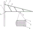
Fig. 1 is a schematic structural diagram of an embodiment of the present invention;
fig. 2 is a schematic view of an embodiment of the reinforcement cage of the present invention during a first rotation step;
fig. 3 is a schematic view of an embodiment of the present invention during a second rotation step of the reinforcement cage;
the meaning of the reference symbols in the figures:
the crane comprises an articulated piece 1, a connecting arm 2, a suspension arm 3, a support column 4, a supporting arm 5, an electric hoist 6, a lifting rope 7 and a hook 8.
Detailed Description
The present invention will be described in detail with reference to the accompanying drawings and specific embodiments.
As shown in fig. 1, the steel reinforcement cage rotating boom device comprises: the steel bar cage lifting device comprises a support column 4 fixed on a factory building, a lifting arm 3 rotatably connected to the stand column, a connecting arm 2 with one end rotatably connected to the other end of the stand column and connected to the lifting arm 3, a supporting arm 5 connected between the connecting arm 2 and the lifting arm 3, a lifting mechanism fixed under the lifting arm 3 and driving a steel bar cage to move in the left-right direction, a traction rope connected to the lifting mechanism and sliding on the lifting mechanism, lifting ropes 7 connected to two ends of the traction rope, and hooks 8 arranged on the lifting ropes 7. Preferably, the hoisting mechanism is an electric hoist 6. The suspension arm 3 and the connecting arm 2 are supported in the middle by a supporting arm 5, and the connecting part of the suspension arm 3 and the connecting arm is anchored by a hinge joint 1.
Preferably, the support 4 is an i-steel support 4, the suspension arm 3 is an i-steel suspension arm 3, the connecting arm 2 is a square pipe steel connecting arm 2, the supporting arm 5 is a square pipe steel supporting arm 5, and the lifting rope 7 is a steel wire rope. Preferably, the arm length of the suspension arm 3 is 6m, and the hoisting weight is more than or equal to 1 ton.
The suspension arm 3 is anchored with the upright post through the articulated piece 1, and the support arm 5 is anchored with the upright post through the articulated piece 1; through the rotation of the suspension arm 3 and the left and right movement of the electric hoist 6, two suspension points at the lifting end of the steel reinforcement cage are stressed uniformly, the deformation of the steel reinforcement cage due to nonuniform stress is avoided, and the production quality is improved.
The length of haulage rope and wire rope needs to make the steel reinforcement cage minimum 1.8m height from the ground, and such design keeps the steel reinforcement cage other end not to contact with ground all the time, avoids steel reinforcement cage both ends to receive ground extrusion and lead to warping.
The operation process of the device is as follows:
in the first step, as shown in fig. 2, the reinforcement cage is hung on one hook 8 from the lifting end to 1/3 of the length of the reinforcement cage, and the other hook 8 is hung on 2/3 of the length of the reinforcement cage from the lifting end, namely, from the other end of the reinforcement cage to 1/3 of the length of the reinforcement cage.
Secondly, as shown in fig. 3, the electric hoist 6 gradually loosens the traction rope, the hook 8 on the traction rope hooks one end of the reinforcement cage horizontally placed on the jig frame, then the electric hoist 6 gradually tightens the traction rope to enable the height of one end of the reinforcement cage to gradually rise, the reinforcement cage gradually leaves the jig frame to be in a vertical state, and the steel wire rope moves in the left and right directions of the electric hoist 6 through the rotation of the suspension arm 3 to enable two suspension points at the lifting end of the reinforcement cage to be evenly stressed until the reinforcement cage is completely in a vertical state; at the moment, the traction rope slides to the positions with the same length at the two ends, and the two hoisting points at the hoisting end of the steel reinforcement cage are stressed uniformly and uniformly. The suspension arm 3 is rotated by the reinforcement cage, and then the reinforcement cage in a vertical state is slowly placed on the ground; and finishing the rotation of the reinforcement cage, and then performing subsequent arrangement and welding work of the reinforcing ribs and the waist ribs.
The workman can be through using this device, and the light steel reinforcement cage of accomplishing is rotatory, and steel reinforcement cage lifts by crane two hoisting points atress in end even, avoids the steel reinforcement cage to warp, and is not only high-efficient, high in production quality moreover.
The foregoing illustrates and describes the principles, general features, and advantages of the present invention. It should be understood by those skilled in the art that the above embodiments do not limit the present invention in any way, and all technical solutions obtained by adopting equivalent replacement or equivalent transformation fall within the protection scope of the present invention.
Claims (7)
1. Rotatory davit device of steel reinforcement cage, its characterized in that includes: the pillar of fixing at the factory building, swivelling joint in the davit of stand, one end swivelling joint is connected in the linking arm of davit at the stand other end, connects the support arm between linking arm and davit, fixes under the davit and drives the hoist mechanism that the steel reinforcement cage left and right sides direction removed, connect in hoist mechanism and slide in hoist mechanism's haulage rope, connect in the lifting rope at haulage rope both ends, set up the couple on the lifting rope.
2. The rebar cage rotating boom apparatus of claim 1, wherein the posts are i-steel posts.
3. The rebar cage rotating boom apparatus of claim 1, wherein the boom is an i-steel boom.
4. The rebar cage rotating boom apparatus of claim 1, wherein the connecting arm is a square tube steel connecting arm.
5. The rebar cage rotating boom apparatus of claim 1, wherein the support arms are square tube steel support arms.
6. The rebar cage rotating boom apparatus of claim 1, wherein the boom is anchored to the column by a hinge and the link arm is anchored to the column by a hinge.
7. The rebar cage rotating boom apparatus of claim 1, wherein the lifting mechanism is an electric hoist.
Priority Applications (1)
| Application Number | Priority Date | Filing Date | Title |
|---|---|---|---|
| CN202021301686.5U CN212609155U (en) | 2020-07-06 | 2020-07-06 | Rotary suspension arm device of steel reinforcement cage |
Applications Claiming Priority (1)
| Application Number | Priority Date | Filing Date | Title |
|---|---|---|---|
| CN202021301686.5U CN212609155U (en) | 2020-07-06 | 2020-07-06 | Rotary suspension arm device of steel reinforcement cage |
Publications (1)
| Publication Number | Publication Date |
|---|---|
| CN212609155U true CN212609155U (en) | 2021-02-26 |
Family
ID=74746132
Family Applications (1)
| Application Number | Title | Priority Date | Filing Date |
|---|---|---|---|
| CN202021301686.5U Active CN212609155U (en) | 2020-07-06 | 2020-07-06 | Rotary suspension arm device of steel reinforcement cage |
Country Status (1)
| Country | Link |
|---|---|
| CN (1) | CN212609155U (en) |
-
2020
- 2020-07-06 CN CN202021301686.5U patent/CN212609155U/en active Active
Similar Documents
| Publication | Publication Date | Title |
|---|---|---|
| CN201106155Y (en) | Inclined guy cable auxiliary full cantaliver crane trussed steel beam device | |
| CN108002244B (en) | Hoisting system and method for high pier column steel bar formwork | |
| CN110468743B (en) | Movable hanging bracket for transformation of old bridge pier cap and construction method | |
| CN111648585A (en) | Construction method and device of suspended support type steel truss platform | |
| CN114182647B (en) | Construction method for lifting and turning weak arch | |
| CN212609155U (en) | Rotary suspension arm device of steel reinforcement cage | |
| CN108625800B (en) | Multifunctional derrick for shaft construction | |
| CN111155438A (en) | Construction equipment applied to steel tower column and construction process thereof | |
| CN216474518U (en) | Innovative prestressed T-beam hogging moment stretching operation frame | |
| CN111877165B (en) | Bailey beam translation device in limited space and construction method thereof | |
| CN211285309U (en) | Traveling type hanging basket for bridge construction | |
| CN112794249B (en) | Prefabricated component's transport vechicle | |
| CN112252195A (en) | Assembly type continuous beam prestressed steel strand whole-bundle tensioning operation trolley and use method thereof | |
| CN202296886U (en) | Hoisting device for installing oversized radial gate of hydropower station | |
| CN220241887U (en) | Precast beam stretch-draw equipment operation frame | |
| JPH0678602B2 (en) | Bridge erection equipment | |
| CN216663844U (en) | Bridge floor transverse prestress tensioning auxiliary device | |
| CN215801072U (en) | Trackless walking hanging basket | |
| CN218434470U (en) | Device for quickly hoisting bridge deck by cable crane | |
| CN219490682U (en) | Basket hanging device for prestress construction of light T-pier cantilever cap beam | |
| CN111377371B (en) | System and method for mounting travelling beam by means of factory building column in closed factory building | |
| CN112942567B (en) | Construction method of self-mounting and dismounting equipment of cement pressure reducing cone template | |
| CN217761016U (en) | Large-section round tunnel bottom arch concrete lining needle beam slip form trolley | |
| CN220434239U (en) | Portable movable freely adjusts vertical height's lifting and pouring car | |
| CN218373379U (en) | Overhanging type operation platform |
Legal Events
| Date | Code | Title | Description |
|---|---|---|---|
| GR01 | Patent grant | ||
| GR01 | Patent grant |