CN212598989U - Hole expanding device for deep hole drilling and boring machine - Google Patents
Hole expanding device for deep hole drilling and boring machine Download PDFInfo
- Publication number
- CN212598989U CN212598989U CN202021150379.1U CN202021150379U CN212598989U CN 212598989 U CN212598989 U CN 212598989U CN 202021150379 U CN202021150379 U CN 202021150379U CN 212598989 U CN212598989 U CN 212598989U
- Authority
- CN
- China
- Prior art keywords
- square
- hole
- boring
- holes
- square block
- Prior art date
- Legal status (The legal status is an assumption and is not a legal conclusion. Google has not performed a legal analysis and makes no representation as to the accuracy of the status listed.)
- Active
Links
Images


Abstract
The utility model relates to a reaming device for a deep hole drilling and boring machine, which comprises a body, a 75-degree boring cutter head arranged on the body, a wood key and a connecting handle, wherein the body is a cylinder with an inner hole, four planes are uniformly distributed on the cylinder along the circumferential direction, four through grooves are milled on four arc edges along the axial direction, and the wood key is arranged in the four through grooves; a square block is milled at the front end of the body, a square through hole is machined in the square block along the radial direction, a threaded hole is machined in the square block, 75-degree boring cutter heads are installed in the two square through holes in the front end of the body, and 75-degree boring cutter heads are fastened by inner hexagonal socket head cap screws which are installed in the threaded holes; the processing has the rectangle screw thread and is used for the tang of location in the body hole, and the processing has the rectangle screw thread on the face of the connection handle outer cylinder, and the connection handle leans on the rectangle screw thread to insert in the body hole, has can improve production efficiency, reduce intensity of labour, realize expanding, the different apertures of boring, avoids changing the cutter body many times and changes the advantage of other auxiliary fixtures.
Description
Technical Field
The utility model belongs to the machining field especially relates to a can improve production efficiency, reduce the reaming device that is used for deep hole boring and boring machine of operative employee's intensity of labour.
Background
In the processing of hollow shaft parts with inner bore diameter phi of 170 mm-220 mm and length of 5000 mm-6000 mm, the prior processing scheme is that a deep hole drilling and boring machine firstly drills a bottom hole and then uses a jacking cutter body for multiple times to enlarge the hole diameter to the size required by a drawing. Therefore, other auxiliary tools such as a jacking cutter body, a boring rod and the like need to be replaced for many times in the machining process, the labor intensity of operators is increased, and the production efficiency is reduced. In order to improve the production efficiency and reduce the labor intensity of operators, a hole expanding device for a deep hole drilling and boring machine needs to be designed.
Disclosure of Invention
An object of the utility model is to overcome exist among the prior art not enough and provide a reaming device for deep hole drilling and boring machine who improves production efficiency, reduces operative employee's intensity of labour.
The technical scheme of the utility model is realized like this: the utility model provides a reaming device for deep hole boring machine, includes the body, installs 75 boring tool bits, wood key and the connecting handle on the body, its characterized in that:
the body is a cylinder with an inner hole, four planes are uniformly milled on the cylinder along the circumferential direction, four through grooves are axially milled on four arc edges, and wood keys are respectively arranged in the four through grooves;
a square block is milled at the front end of the body, square through holes are machined in the square block along the radial direction, threaded holes are machined in the square block, 75-degree boring heads are installed in the two square through holes in the front end of the body, and 75-degree boring heads are attached to the headrest and fastened through hexagon socket head cap screws in the threaded holes in the square block;
the inner hole of the body is provided with a rectangular thread and a spigot for positioning, the outer cylindrical surface of the connecting handle which is hollow inside is also provided with a rectangular thread, and the connecting handle is inserted into the inner hole of the body by the rectangular thread.
An oil discharge port which forms an angle of 35 degrees with the axis is processed at the bottom of the inner hole of the body.
Two square through holes are processed on the square block along the radial direction, threaded holes penetrating through the square through holes are processed on the square block, two threaded holes are formed outside each square through hole, 75-degree boring cutter heads are respectively arranged in the two square through holes and fastened by inner hexagonal socket head screws arranged in the four threaded holes.
The body is connected with the boring rod through the connecting handle, the connecting handle is connected with the body through the outer rectangular thread at the front end of the connecting handle, and then the connecting handle is connected with the boring rod through the outer rectangular thread at the back.
The utility model discloses have following positive effect: when hollow shaft parts with the aperture of phi 170 mm-phi 220mm and the length of 5000 mm-6000 mm are machined, the traditional machining scheme is that a bottom hole is firstly drilled on a deep hole drilling and boring machine, and then a trepanning cutter body is used for multiple times to enlarge the aperture to the size required by a drawing. Therefore, other auxiliary tools such as a jacking cutter body, a boring rod and the like need to be replaced for many times in the machining process, the labor intensity of operators is increased, and the production efficiency is reduced. And the utility model has the advantages of can improve production efficiency, reduce operative employee's intensity of labour, realize expanding, the different apertures of boring, avoid changing the cutter body many times and change other auxiliary fixtures.
Drawings
Fig. 1 is the schematic structural diagram of the reaming device of the present invention.
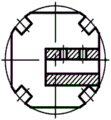
Fig. 2 is a left side view of the reaming device structure of the present invention.
Fig. 3 is a front view of the body of the present invention.
Fig. 4 is a left side view of the middle body of the present invention.
Fig. 5 is a top view of the body of the present invention.
Fig. 6 is a partial schematic view of the internal thread (rectangular thread) of the middle body of the present invention.
Fig. 7 is a front view of the connecting handle of the present invention.
Fig. 8 is a sectional view taken along the line a-a of the connecting handle of the present invention.
Fig. 9 is a partial schematic view of the external thread (rectangular thread) of the middle connection handle of the present invention.
The labels in the figures are: 1. the inner hexagonal socket head cap screw 2, the body 3, the connecting handle 4, the wood key 5 and the 75-degree boring cutter head.
Detailed Description
As shown in the figure, a reaming device for a deep hole drilling and boring machine comprises a body 2, a 75-degree boring head 5 installed on the body 2, a wood key 4 and a connecting handle 3, and is characterized in that:
the body 2 is a cylinder with an inner hole, four planes are uniformly milled on the cylinder along the circumferential direction, four through grooves are axially milled on four arc edges, and wood keys 4 are respectively arranged in the four through grooves;
a square block is milled at the front end of the body 2, square through holes are machined in the square block along the radial direction, threaded holes are machined in the square block, 75-degree boring cutter heads 5 are installed in the two square through holes in the front end of the body 2, and the 75-degree boring cutter heads 5 are fastened by inner hexagonal socket head cap screws 1 in the threaded holes installed in the square block;
rectangular screw threads and a spigot used for positioning are machined in an inner hole of the body 2, rectangular screw threads are also machined on an outer cylindrical surface of the connecting handle 3, and the connecting handle 3 is inserted into the inner hole of the body 2 through the rectangular screw threads.
An oil discharge port forming an angle of 35 degrees with the axis is processed at the bottom of the inner hole of the body 2.
Two square through holes are processed on the square block along the radial direction, threaded holes penetrating through the square through holes are processed on the square block, two threaded holes are formed outside each square through hole, 75-degree boring cutter heads are respectively arranged in the two square through holes and fastened by inner hexagonal socket head screws arranged in the four threaded holes.
The body 2 is connected with the boring bar through the connecting handle 3, the connecting handle 3 is connected with the body 2 through the external rectangular thread at the front end of the connecting handle, and then is connected with the boring bar through the external rectangular thread at the back.
The inside of the connecting handle 3 is hollow.
The specific installation steps are as follows:
1. and (3) putting the 75-degree boring cutter head 5 into the two square through holes at the front end of the body 2, and fastening the 75-degree boring cutter head by using the hexagon socket head cap screws 1 after assembly.
2. The four through grooves of the body 2 are respectively provided with a wood key 4.
3. The connecting handle 3 is connected with the body 2 through the external rectangular thread at the front end and then connected with the boring bar through the external rectangular thread at the back.
And adjusting the extension lengths of the two 75-degree boring cutter heads according to the aperture size and the bottom hole size of the inner hole of the workpiece, and boring different apertures.
In the reaming process, the device can realize the reaming and boring of different apertures by adjusting the extension length of the boring cutter head of 75 degrees, avoids the cutter body replacement and other auxiliary tools replacement for many times, improves the production efficiency and reduces the labor intensity of operators.
Claims (4)
1. The utility model provides a reaming device for deep hole boring machine, includes body (2), install 75 boring tool bits (5), wood key (4) and connecting handle (3) on body (2), its characterized in that:
the body (2) is a cylinder with an inner hole, four planes are uniformly milled on the cylinder along the circumferential direction, four through grooves are axially milled on four arc edges, and wood keys (4) are respectively arranged in the four through grooves;
a square block is milled at the front end of the body (2), a square through hole is machined in the square block along the radial direction, a threaded hole is machined in the square block, 75-degree boring cutter heads (5) are installed in the two square through holes in the front end of the body (2), and the 75-degree boring cutter heads (5) are fastened by inner hexagonal socket head cap screws (1) installed in the threaded holes in the square block;
the inner hole of the body (2) is provided with a rectangular thread and a spigot for positioning, the outer cylindrical surface of the connecting handle (3) is also provided with a rectangular thread, and the connecting handle (3) is inserted into the inner hole of the body (2) by the rectangular thread.
2. The reaming device for the deep hole drilling and boring machine as claimed in claim 1, wherein: an oil discharge port which forms an angle of 35 degrees with the axis is processed at the bottom of the inner hole of the body (2).
3. The reaming device for the deep hole drilling and boring machine as claimed in claim 1, wherein: two square through holes are processed on the square block along the radial direction, threaded holes penetrating through the square through holes are processed on the square block, two threaded holes are formed outside each square through hole, 75-degree boring cutter heads are respectively arranged in the two square through holes and fastened by inner hexagonal socket head screws arranged in the four threaded holes.
4. The reaming device for the deep hole drilling and boring machine as claimed in claim 1, wherein:
the body (2) is connected with the boring bar through the connecting handle (3), the connecting handle (3) is connected with the body (2) through the external rectangular thread at the front end of the connecting handle, and then is connected with the boring bar through the external rectangular thread at the back.
Priority Applications (1)
| Application Number | Priority Date | Filing Date | Title |
|---|---|---|---|
| CN202021150379.1U CN212598989U (en) | 2020-06-19 | 2020-06-19 | Hole expanding device for deep hole drilling and boring machine |
Applications Claiming Priority (1)
| Application Number | Priority Date | Filing Date | Title |
|---|---|---|---|
| CN202021150379.1U CN212598989U (en) | 2020-06-19 | 2020-06-19 | Hole expanding device for deep hole drilling and boring machine |
Publications (1)
| Publication Number | Publication Date |
|---|---|
| CN212598989U true CN212598989U (en) | 2021-02-26 |
Family
ID=74755811
Family Applications (1)
| Application Number | Title | Priority Date | Filing Date |
|---|---|---|---|
| CN202021150379.1U Active CN212598989U (en) | 2020-06-19 | 2020-06-19 | Hole expanding device for deep hole drilling and boring machine |
Country Status (1)
| Country | Link |
|---|---|
| CN (1) | CN212598989U (en) |
-
2020
- 2020-06-19 CN CN202021150379.1U patent/CN212598989U/en active Active
Similar Documents
| Publication | Publication Date | Title |
|---|---|---|
| CN102717239B (en) | Method for machining connecting rod of air compressor and drilling and hinging fixture | |
| CN215510003U (en) | Self-centering tool for machining center hole in end face of shaft head | |
| CN200984656Y (en) | Quick change drill clamping head for drilling and cutting | |
| CN210848371U (en) | Adjustable boring machine tool | |
| CN212598989U (en) | Hole expanding device for deep hole drilling and boring machine | |
| CN205362791U (en) | A composite drill bit for thin wall hole machining | |
| CN201128015Y (en) | High-efficiency drill chamfering chuck | |
| CN208391098U (en) | A kind of shift case specific complex drills and reams milling cutter | |
| CN212704419U (en) | Numerical control turning and boring cutter head | |
| CN202964204U (en) | Threading clamp | |
| CN105499663A (en) | Compound drill bit for thin-wall small hole machining | |
| CN220533128U (en) | Reaming drill sleeve with thread guide | |
| CN215033719U (en) | Commutator boring chuck capable of reducing excircle run-out | |
| CN220178197U (en) | Boring device for realizing rough boring, semi-finish boring and floating boring of inner holes of hollow shaft parts at one time | |
| CN214264633U (en) | High-performance self-tapping locking screw | |
| CN220216839U (en) | Big aperture hole countersink tool for machine with replaceable guide head | |
| CN218946932U (en) | Machining tool apron suitable for BTA deep hole drilling and boring machine | |
| CN217647519U (en) | Rough boring and floating boring integrated boring device of deep hole drilling and boring machine | |
| CN218891211U (en) | Long hole length and multiple diameter metal cutting lengthening tool | |
| CN217749493U (en) | Long suspended depth trepanning machining tool with mechanically clamped blades | |
| CN220030481U (en) | Graphite hard felt drilling tool | |
| CN218873856U (en) | Screwdriver head quick-connection counter bore drill bit | |
| CN218964137U (en) | Novel bore reamer | |
| CN216938572U (en) | Wear-resisting type industry titanium-plated drill bit structure | |
| CN211052559U (en) | Boring cutter bar for boring large-diameter hole of part |
Legal Events
| Date | Code | Title | Description |
|---|---|---|---|
| GR01 | Patent grant | ||
| GR01 | Patent grant |