CN212578335U - Polishing machine capable of rotating in multiple directions for bracket - Google Patents
Polishing machine capable of rotating in multiple directions for bracket Download PDFInfo
- Publication number
- CN212578335U CN212578335U CN202021195921.5U CN202021195921U CN212578335U CN 212578335 U CN212578335 U CN 212578335U CN 202021195921 U CN202021195921 U CN 202021195921U CN 212578335 U CN212578335 U CN 212578335U
- Authority
- CN
- China
- Prior art keywords
- plate
- rod
- top surface
- polishing
- transversely
- Prior art date
- Legal status (The legal status is an assumption and is not a legal conclusion. Google has not performed a legal analysis and makes no representation as to the accuracy of the status listed.)
- Active
Links
Images


Abstract
The utility model discloses a polishing machine for a bracket capable of rotating in multiple directions, which comprises a base, wherein stand columns are vertically and fixedly arranged at the middle parts of the two sides of the top surface of the base, transverse plates are horizontally and fixedly arranged at the top parts of the inner side surfaces of the stand columns, and an electric pushing cylinder is arranged on the top surface of each transverse plate; a lifting plate is horizontally arranged in the middle between the inner side surfaces of the two upright posts; vertical rods which are vertically arranged are fixedly arranged on two sides of the middle part of the top surface of the lifting plate, and a polishing assembly is arranged between the two vertical rods; the top surface of the placing plate is provided with a clamping component; an adjusting component is arranged in the adjusting cavity; the utility model is convenient to operate, and solves the problem that the prior artificial tooth is inconvenient to clamp and fix during polishing through the clamping component; the bearing between the placing plate and the supporting rod is convenient for angular rotation during the polishing of the false tooth; the problem that the false tooth is inconvenient to rotate in an angle during polishing is solved; the working efficiency of the false tooth during polishing is effectively improved through the adjusting assembly.
Description
Technical Field
The utility model relates to a technical field of artificial tooth polishing especially relates to burnishing machine for support that can diversely rotate.
Background
The artificial tooth is also called false tooth, it is a method for repairing the artificial tooth that lacks by using artificial method, it is a general name of the prosthesis made after the upper and lower jaw tooth is partly or totally lost in medicine, the false tooth is divided into removable and fixed two kinds, the fixed false tooth can not be taken and worn by patient oneself, but the removable false tooth can be taken and worn by patient conveniently, the false tooth needs to polish in the course of production, the existing false tooth polishing device has the following disadvantages: 1. the existing denture polishing device is inconvenient for rapidly clamping and fixing the denture during polishing; 2. in the denture grinding process, because the denture is fixed on the working table and the position of the denture is fixed, the denture is inconvenient to rotate and polish some details; 3. the existing denture polishing device has the defects of poor denture polishing effect and low working efficiency of workers during polishing; and make optimization improvements to the above disadvantages.
SUMMERY OF THE UTILITY MODEL
The utility model aims at solving the defect of poor practicability in the prior art and providing a polishing machine for a bracket capable of rotating in multiple directions.
In order to achieve the above purpose, the utility model adopts the following technical scheme: the polishing machine for the support capable of rotating in multiple directions comprises a base, wherein the base is in a horizontally arranged rectangular plate shape, stand columns are vertically and fixedly arranged in the middle of two sides of the top surface of the base, a transverse plate is horizontally and fixedly arranged at the top of the inner side surface of each stand column, a circular mounting hole is vertically formed in the middle of the top surface of each transverse plate, and an electric pushing cylinder is vertically and fixedly arranged in each mounting hole; a lifting plate is horizontally arranged in the middle between the inner side surfaces of the two stand columns, and the bottom of the telescopic end of each electric pushing cylinder is fixedly connected with the top surface of the lifting plate; a rectangular motor box is fixedly arranged in the middle of the top surface of the lifting plate, and a motor is transversely and fixedly arranged in the motor box; a transmission component is arranged on one side of the middle part of the top surface of the lifting plate; the two sides of the middle part of the top surface of the lifting plate are fixedly provided with vertical rods which are vertically arranged, the bottom end of each vertical rod is fixedly provided with a first bearing which is vertically arranged, and a polishing assembly is arranged between the two vertical rods;
a T-shaped sliding rail is transversely and fixedly arranged on the top surface of the base between the two upright posts, a sliding plate is horizontally and movably arranged on the T-shaped sliding rail, and a T-shaped sliding groove is transversely formed in the middle of the bottom surface of the sliding plate in a matched manner with the T-shaped sliding rail; a supporting rod is vertically and fixedly installed in the middle of the top surface of the sliding plate, a rectangular placing plate is horizontally arranged above the supporting rod, a third bearing is fixedly installed in the middle of the bottom surface of the placing plate, and the top end of the supporting rod is fixedly connected into an inner ring of the third bearing; a clamping component is arranged on the top surface of the placing plate; the middle part in the base is transversely provided with a rectangular adjusting cavity, and an adjusting component is arranged in the adjusting cavity.
Preferably, the polishing assembly comprises a rotating rod, a rough polishing wheel, a medium rough polishing wheel and a fine polishing wheel, the rotating rod is transversely arranged between the two first bearings, and two ends of the rotating rod are fixedly connected in inner rings of the first bearings; a middle rough polishing wheel is fixedly sleeved in the middle of the rod body of the rotating rod, and a rough polishing wheel and a fine polishing wheel are respectively fixedly sleeved on the rotating rod body at two sides of the middle rough polishing wheel; an arc-shaped plate-shaped protective cover is fixedly installed on the bottom surface of the lifting plate between the two vertical rods, and the inner arc surface of the protective cover is arranged downwards.
Preferably, transmission assembly includes transfer line, initiative awl tooth, passive awl tooth and driven awl tooth one side at lifter plate top surface middle part is vertical has seted up the bearing groove bearing inslot fixed mounting has the bearing fixed mounting has the transfer line of vertical setting in the inner circle of bearing the both ends of transfer line are all fixed the cover and are equipped with the passive awl tooth of horizontal setting the fixed cover of one end of dwang is equipped with the driven awl tooth of vertical setting, the motor shaft of motor passes through outside wearing out the motor case the fixed initiative awl tooth that is equipped with vertical setting in motor shaft top of motor, just the passive awl tooth meshing transmission on initiative awl tooth and transfer line top, the passive awl tooth and the driven awl tooth meshing transmission of transfer line bottom.
Preferably, the adjusting assembly comprises a screw rod, a threaded cylinder and a connecting plate, fourth bearings are fixedly mounted on the inner walls of the two sides of the adjusting cavity, the screw rod is transversely arranged in the adjusting cavity, and the two ends of the screw rod are fixedly connected in the inner ring of the fourth bearing; a threaded cylinder is movably sleeved on a rod body of the lead screw, and a vertically arranged connecting plate is fixedly connected to the top of a cylinder body of the threaded cylinder; a strip-shaped opening is formed in the top surface of the base of the front end face of the T-shaped slide rail along the length direction, and the top end of the connecting plate extends out of the strip-shaped opening to be fixedly connected with the bottom surface of the slide plate; one end of the screw rod penetrates out of the adjusting cavity, and a hand wheel is fixedly connected to one end of the screw rod, which is positioned outside the adjusting cavity.
Preferably, the clamping assembly comprises a fixed plate, a threaded sleeve, a threaded rod and a clamping plate, the fixed plate is vertically and fixedly mounted on both sides of the top surface of the placing plate, a circular through hole is transversely formed in the outer side of the fixed plate on one side of the top surface of the placing plate, the threaded sleeve is transversely and fixedly mounted in the circular through hole, the threaded rod is spirally connected in the threaded sleeve, the rectangular clamping plate is vertically and movably mounted on the top surface of the placing plate, a fifth bearing is fixedly mounted in the middle of one side of the clamping plate, and the inner end of the threaded rod is fixedly connected in an inner ring of the fifth bearing; and a handle is fixedly connected with the outer end of the threaded rod.
Preferably, place one side at board top surface middle part and transversely seted up banding rectangular channel horizontal fixed mounting has the guide bar in the rectangular channel the activity cover is equipped with the sleeve pipe on the body of rod of guide bar the activity cover is equipped with the clamp spring on the guide bar body of rod of sleeve pipe one side, just the both ends of clamp spring respectively with sleeve pipe one side body and one side inner wall rigid coupling of rectangular channel, the bottom surface middle part and the sheathed tube body top rigid coupling of splint.
Compared with the prior art, the beneficial effects of the utility model are that: in the utility model, the water-saving device is provided with a water-saving valve,
1. the guide rod and the sleeve are convenient for effectively improving the stability of the clamping plate when clamping the false tooth; meanwhile, the clamping plate can stably move when moving; the working efficiency of fixing the false teeth during polishing is effectively increased through the clamping assembly, and the false teeth with different sizes can be clamped and fixed effectively; the problem that the existing artificial tooth is inconvenient to clamp and fix during polishing is solved;
2. the bearing between the placing plate and the supporting rod is convenient for angular rotation during the polishing of the false tooth; the false tooth is driven to horizontally rotate through the rotation of the placing plate, so that the polishing operation of the polishing wheel on the false tooth at each angle is facilitated; the angle diversity of the false tooth during polishing is effectively increased; the problem that after the existing denture polishing device is used for fixing the denture, the denture is not convenient to rotate in an angle during polishing is solved;
3. the polishing effect on the false tooth is effectively improved through the rough polishing wheel, the middle rough polishing wheel and the fine polishing wheel; the quality of the denture polishing product is improved conveniently and effectively; the problem that the existing denture polishing device has poor denture polishing effect is solved; the adjusting assembly is convenient for the movement operation of workers during the grinding of the false teeth, so that the workload of the workers is effectively reduced; the working efficiency of the artificial tooth during polishing is effectively improved.
Drawings
The accompanying drawings, which are included to provide a further understanding of the invention and are incorporated in and constitute a part of this application, illustrate embodiment(s) of the invention and together with the description serve to explain the invention without limitation. In the drawings:
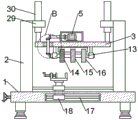
fig. 1 is a schematic view of a front view structure provided by the present invention;
fig. 2 is a schematic view of a front view cross-sectional structure provided by the present invention;
FIG. 3 is an enlarged schematic view of the structure of the part A according to the present invention;
FIG. 4 is an enlarged schematic view of the structure of the part B according to the present invention;
fig. 5 is a schematic view of a cross-sectional structure of one side of the lifting plate provided by the present invention;
number in the figure: the device comprises a base 1, a stand column 2, a lifting plate 3, a motor box 4, a motor 5, a transmission rod 6, a vertical rod 7, a first bearing 8, a T-shaped sliding rail 9, a sliding plate 10, a supporting rod 11, a placing plate 12, a rotating rod 13, a rough polishing wheel 14, a middle rough polishing wheel 15, a fine polishing wheel 16, a screw rod 17, a threaded cylinder 18, a driving bevel gear 19, a driven bevel gear 20, a driven bevel gear 21, a fixing plate 22, a threaded sleeve 23, a threaded rod 24, a guide rod 25, a sleeve 26, a clamping spring 27, a clamping plate 28, a transverse plate 29, an electric pushing cylinder 30 and a protective cover 31.
Detailed Description
The technical solutions in the embodiments of the present invention will be described clearly and completely with reference to the accompanying drawings in the embodiments of the present invention, and it is obvious that the described embodiments are only some embodiments of the present invention, not all embodiments.
Example 1: referring to fig. 1-5, the polishing machine for a bracket capable of rotating in multiple directions in the present invention comprises a base 1, wherein the base 1 is a horizontally arranged rectangular plate, stand columns 2 are vertically and fixedly installed in the middle of two sides of the top surface of the base 1, a transverse plate 29 is horizontally and fixedly installed at the top of the inner side surface of each stand column 2, a circular installation hole is vertically formed in the middle of the top surface of each transverse plate 29, a vertically arranged electric pushing cylinder 30 is fixedly installed in each installation hole, and the electric pushing cylinder 30 is of a JND30 model; a lifting plate 3 is horizontally arranged in the middle between the inner side surfaces of the two upright posts 2, and the bottom of the telescopic end of each electric pushing cylinder 30 is fixedly connected with the top surface of the lifting plate 3; a rectangular motor box 4 is fixedly installed in the middle of the top surface of the lifting plate 3, a motor 5 is transversely and fixedly installed in the motor box 4, and the model of the motor 5 is T63B 4; a transmission component is arranged on one side of the middle part of the top surface of the lifting plate 3; vertical rods 7 which are vertically arranged are fixedly arranged on two sides of the middle part of the top surface of the lifting plate 3, a first bearing 8 which is vertically arranged is fixedly arranged at the bottom end of each vertical rod 7, and a polishing assembly is arranged between the two vertical rods 7; a T-shaped slide rail 9 is transversely and fixedly arranged on the top surface of the base 1 between the two upright posts 2, a slide plate 10 is horizontally and movably arranged on the T-shaped slide rail 9, and a T-shaped sliding groove is transversely formed in the middle of the bottom surface of the slide plate 10 in a matched manner with the T-shaped slide rail 9; a supporting rod 11 is vertically and fixedly installed in the middle of the top surface of the sliding plate 10, a rectangular placing plate 12 is horizontally arranged above the supporting rod 11, a third bearing is fixedly installed in the middle of the bottom surface of the placing plate 12, and the top end of the supporting rod 11 is fixedly connected in an inner ring of the third bearing; a clamping component is arranged on the top surface of the placing plate 12; the middle part in the base 1 is transversely provided with a rectangular adjusting cavity, and an adjusting component is arranged in the adjusting cavity.
In the utility model, the polishing component comprises a rotating rod 13, a rough polishing wheel 14, a middle rough polishing wheel 15 and a fine polishing wheel 16, the rotating rod 13 is transversely arranged between two first bearings 8, and both ends of the rotating rod 13 are fixedly connected in the inner ring of the first bearings 8; a middle rough polishing wheel 15 is fixedly sleeved at the middle part of the rod body of the rotating rod 13, and a rough polishing wheel 14 and a fine polishing wheel 16 are respectively and fixedly sleeved on the rod bodies of the rotating rod 13 at two sides of the middle rough polishing wheel 15; an arc-shaped plate-shaped protective cover 31 is fixedly arranged on the bottom surface of the lifting plate 3 between the two vertical rods 7, and the inner arc surface of the protective cover 31 is arranged downwards.
The utility model discloses in, drive assembly includes transfer line 6, initiative awl tooth 19, passive awl tooth 20 and driven awl tooth 21 the vertical bearing groove of having seted up in one side at 3 top surfaces middle parts of lifter plate bearing inslot fixed mounting has the bearing fixed mounting has the transfer line 6 of vertical setting in the inner circle of bearing the equal fixed cover in both ends of transfer line 6 is equipped with the passive awl tooth 20 of horizontal setting the fixed cover in one end of dwang 13 is equipped with the driven awl tooth 21 of vertical setting, outside motor 5's motor shaft runs through out motor case 4 the fixed initiative awl tooth 19 that is equipped with vertical setting in motor 5's the fixed cover in motor shaft top, just initiative awl tooth 19 meshes the transmission with the passive awl tooth 20 on 6 tops of transfer line, the passive awl tooth 20 and the driven awl tooth 21 mesh transmission of 6 bottoms of transfer line.
In the utility model, the adjusting component comprises a lead screw 17, a thread cylinder 18 and a connecting plate, fourth bearings are fixedly arranged on the inner walls of the two sides of the adjusting cavity, the lead screw 17 is transversely arranged in the adjusting cavity, and the two ends of the lead screw 17 are fixedly connected in the inner ring of the fourth bearing; a threaded cylinder 18 is movably sleeved on the rod body of the lead screw 17, and a vertically arranged connecting plate is fixedly connected to the top of the cylinder body of the threaded cylinder 18; a strip-shaped opening is formed in the top surface of the base 1 on the front end face of the T-shaped slide rail 9 along the length direction, and the top end of the connecting plate extends out of the strip-shaped opening to be fixedly connected with the bottom surface of the slide plate 10; one end of the screw rod 17 penetrates out of the adjusting cavity, and a hand wheel is fixedly connected to one end of the screw rod 17, which is positioned outside the adjusting cavity; the adjusting assembly is convenient for the movement operation of workers during the grinding of the false teeth, so that the workload of the workers is effectively reduced; the working efficiency of the artificial tooth during polishing is effectively improved.
The utility model discloses in, the centre gripping subassembly includes fixed plate 22, threaded sleeve 23, threaded rod 24 and splint 28 place the top surface both sides of board 12 all vertical fixed mounting have fixed plate 22, place the fixed plate 22 outside of board 12 top surface one side transversely seted up circular through-hole, transversely fixed mounting has threaded sleeve 23 in the circular through-hole, threaded rod 24 is connected with to the spiral in threaded sleeve 23, place the top surface vertical movable mounting of board 12 has rectangular splint 28, in one side middle part fixed mounting of splint 28 has a fifth bearing, and the inner rigid coupling of threaded rod 28 is in the inner circle of fifth bearing; a handle is fixedly connected to the outer end of the threaded rod 28; a strip-shaped rectangular groove is transversely formed in one side of the middle of the top surface of the placing plate 12, a guide rod 25 is transversely and fixedly installed in the rectangular groove, a sleeve 26 is movably sleeved on a rod body of the guide rod 25, a clamping spring 27 is movably sleeved on the rod body of the guide rod 25 on one side of the sleeve 26, two ends of the clamping spring 27 are fixedly connected with a pipe body on one side of the sleeve 26 and the inner wall on one side of the rectangular groove respectively, and the middle of the bottom surface of the clamping plate 28 is fixedly connected with the top of the pipe body of the sleeve 26; the working efficiency of fixing the false teeth during polishing is effectively increased through the clamping assembly, and effective clamping and fixing can be conveniently carried out according to false teeth of different sizes.
Example 2: when the utility model is used, firstly, the motor 5 and the electric pushing cylinder 30 are respectively and electrically connected with an external power supply through guiding; then the false tooth to be polished is placed on the top surface of the placing plate 12, then the handle is rotated to drive the threaded rod 24 to rotate in the threaded sleeve 23, and the threaded rod 24 is rotated and pushed to conveniently push the clamping plate 28 to clamp and fix the false tooth; by facilitating support of the sleeve 26 under the spring force of the clamping force spring 27; the guide rod 25 and the sleeve 26 are used for effectively improving the stability of the clamping plate 28 when clamping the false tooth; and at the same time, it is convenient to play a role of stably moving the clamping plate 28 when moving; the working efficiency of fixing the false teeth during polishing is effectively increased through the clamping assembly, and the false teeth with different sizes can be clamped and fixed effectively; the problem that the existing artificial tooth is inconvenient to clamp and fix during polishing is solved; after the clamping and fixing of the false tooth are finished; the lifting plate 3 is driven to lift by controlling the stretching of the electric pushing cylinder 30, and the transmission assembly and the polishing assembly on the top surface of the plate body are driven to lift and adjust by lifting the lifting plate 3; after the height of the polishing component is adjusted, the driving bevel gear 19 is driven to rotate conveniently by controlling the rotation of the motor 5, the driven bevel gear 20 at the bottom end of the transmission rod 6 is driven to rotate conveniently by the meshing transmission of the driving bevel gear 19 and the driven bevel gear 20 at the top end of the transmission rod 6, the rotating rod 13 is driven to rotate conveniently by the meshing transmission of the driven bevel gear 20 at the bottom end of the transmission rod 6 and the driven bevel gear 21, and the rough polishing wheel 14, the medium rough polishing wheel 15 and the fine polishing wheel 16 on the rod body are driven to rotate conveniently by the rotation of the rotating rod 13;
after the false tooth is primarily polished by the rough polishing wheel 14, the lead screw 17 is driven to rotate by rotating the hand wheel, the threaded cylinder 18 is driven to move transversely on the rod body by the rotation of the lead screw 17, the sliding plate 10 at the top end of the connecting plate is driven to slide transversely on the T-shaped sliding rail 9 by the transverse movement of the threaded cylinder 18, and the stability of the sliding plate 10 during movement is effectively improved by the T-shaped sliding rail 9; meanwhile, the integral connection strength is increased; the placing plate 12 at the top end of the supporting rod 11 is driven to move transversely by the movement of the sliding plate 10, the false teeth fixedly clamped on the top surface are driven to move to the polishing area of the middle rough polishing wheel 15 by the movement of the placing plate 12, the false teeth are polished for the second time by the middle rough polishing wheel 15, and the smoothness of the surface of the false teeth is effectively improved by polishing the false teeth for the second time;
after finishing polishing the false teeth by the medium-coarse polishing wheel 15, continuously rotating the hand wheel to drive the adjusting component to rotate, and continuously enabling the placing plate 12 to drive the false teeth fixedly clamped on the top surface to move to the polishing area of the fine polishing wheel 16; then, the final polishing work is carried out on the false tooth through the fine polishing wheel 16, and the bearing between the placing plate 12 and the supporting rod 11 is used for facilitating the angle rotation during the false tooth polishing; the false tooth is driven to horizontally rotate by the rotation of the placing plate 12, so that the polishing operation of the polishing wheel on the false tooth at all angles is facilitated; the angle diversity of the false tooth during polishing is effectively increased; the problem that after the existing denture polishing device is used for fixing the denture, the denture is not convenient to rotate in an angle during polishing is solved; taking down the false tooth after finishing the polishing work; the polishing effect on the false tooth is effectively increased through the rough polishing wheel 14, the middle rough polishing wheel 15 and the fine polishing wheel 16; the quality of the denture polishing product is improved conveniently and effectively; the problem that the existing denture polishing device has poor denture polishing effect is solved; the adjusting assembly is convenient for the movement operation of workers during the grinding of the false teeth, so that the workload of the workers is effectively reduced; the working efficiency of the artificial tooth during polishing is effectively improved.
The above, only be the concrete implementation of the preferred embodiment of the present invention, but the protection scope of the present invention is not limited thereto, and any person skilled in the art is in the technical scope of the present invention, according to the technical solution of the present invention and the utility model, the concept of which is equivalent to replace or change, should be covered within the protection scope of the present invention.
Claims (6)
1. Burnishing machine for support that can diversely rotate, including base (1), its characterized in that: the base (1) is in a horizontally arranged rectangular plate shape, stand columns (2) are vertically and fixedly installed in the middle of two sides of the top surface of the base (1), a transverse plate (29) is horizontally and fixedly installed at the top of the inner side surface of each stand column (2), a circular installation hole is vertically formed in the middle of the top surface of each transverse plate (29), and an electric pushing cylinder (30) is vertically and fixedly installed in each installation hole; a lifting plate (3) is horizontally arranged in the middle between the inner side surfaces of the two upright posts (2), and the bottom of the telescopic end of each electric pushing cylinder (30) is fixedly connected with the top surface of the lifting plate (3); a rectangular motor box (4) is fixedly arranged in the middle of the top surface of the lifting plate (3), and a motor (5) is transversely and fixedly arranged in the motor box (4); a transmission component is arranged on one side of the middle part of the top surface of the lifting plate (3); vertical rods (7) which are vertically arranged are fixedly arranged on two sides of the middle part of the top surface of the lifting plate (3), a first bearing (8) which is vertically arranged is fixedly arranged at the bottom end of each vertical rod (7), and a polishing assembly is arranged between the two vertical rods (7);
a T-shaped sliding rail (9) is transversely and fixedly arranged on the top surface of the base (1) between the two upright posts (2), a sliding plate (10) is horizontally and movably arranged on the T-shaped sliding rail (9), and a T-shaped sliding groove is transversely formed in the middle of the bottom surface of the sliding plate (10) in a matched manner with the T-shaped sliding rail (9); a supporting rod (11) is vertically and fixedly installed in the middle of the top surface of the sliding plate (10), a rectangular placing plate (12) is horizontally arranged above the supporting rod (11), a third bearing is fixedly installed in the middle of the bottom surface of the placing plate (12), and the top end of the supporting rod (11) is fixedly connected into an inner ring of the third bearing; a clamping component is arranged on the top surface of the placing plate (12); the middle part in the base (1) is transversely provided with a rectangular adjusting cavity, and an adjusting component is arranged in the adjusting cavity.
2. The polishing machine capable of rotating in multiple directions for a bracket of claim 1, wherein: the polishing component comprises a rotating rod (13), a rough polishing wheel (14), a medium rough polishing wheel (15) and a fine polishing wheel (16), the rotating rod (13) is transversely arranged between the two first bearings (8), and two ends of the rotating rod (13) are fixedly connected into inner rings of the first bearings (8); a middle rough polishing wheel (15) is fixedly sleeved in the middle of the rod body of the rotating rod (13), and a rough polishing wheel (14) and a fine polishing wheel (16) are respectively fixedly sleeved on the rod bodies of the rotating rod (13) at two sides of the middle rough polishing wheel (15); an arc-shaped plate-shaped protective cover (31) is fixedly arranged on the bottom surface of the lifting plate (3) between the two vertical rods (7), and the inner arc surface of the protective cover (31) is arranged downwards.
3. The machine of claim 2, wherein: the transmission component comprises a transmission rod (6), a driving bevel gear (19), a driven bevel gear (20) and a driven bevel gear (21), a bearing groove is vertically arranged on one side of the middle part of the top surface of the lifting plate (3), a bearing is fixedly arranged in the bearing groove, a vertically arranged transmission rod (6) is fixedly arranged in an inner ring of the bearing, driven bevel gears (20) which are transversely arranged are fixedly sleeved at both ends of the transmission rod (6), one end of the rotating rod (13) is fixedly sleeved with a vertically arranged driven bevel gear (21), a motor shaft of the motor (5) penetrates through the motor box (4), a driving bevel gear (19) which is vertically arranged is fixedly sleeved at the top end of a motor shaft of the motor (5), and the driving bevel gear (19) is meshed with a driven bevel gear (20) at the top end of the transmission rod (6) for transmission, and the driven bevel gear (20) at the bottom end of the transmission rod (6) is in meshed transmission with the driven bevel gear (21).
4. The polishing machine capable of rotating in multiple directions for a bracket of claim 1, wherein: the adjusting assembly comprises a lead screw (17), a threaded cylinder (18) and a connecting plate, fourth bearings are fixedly mounted on the inner walls of the two sides of the adjusting cavity, the lead screw (17) is transversely arranged in the adjusting cavity, and the two ends of the lead screw (17) are fixedly connected in the inner ring of the fourth bearings; a threaded cylinder (18) is movably sleeved on a rod body of the lead screw (17), and a vertically arranged connecting plate is fixedly connected to the top of a cylinder body of the threaded cylinder (18); a strip-shaped opening is formed in the top surface of the base (1) on the front end face of the T-shaped sliding rail (9) along the length direction, and the top end of the connecting plate extends out of the strip-shaped opening to be fixedly connected with the bottom surface of the sliding plate (10); one end of the screw rod (17) penetrates out of the adjusting cavity, and a hand wheel is fixedly connected to one end, located outside the adjusting cavity, of the screw rod (17).
5. The polishing machine capable of rotating in multiple directions for a bracket of claim 1, wherein: the clamping assembly comprises a fixing plate (22), a threaded sleeve (23), a threaded rod (24) and a clamping plate (28), wherein the fixing plate (22) is vertically and fixedly installed on two sides of the top surface of the placing plate (12), a circular through hole is transversely formed in the outer side of the fixing plate (22) on one side of the top surface of the placing plate (12), the threaded sleeve (23) is transversely and fixedly installed in the circular through hole, the threaded rod (24) is spirally connected in the threaded sleeve (23), the rectangular clamping plate (28) is vertically and movably installed on the top surface of the placing plate (12), a fifth bearing is fixedly installed in the middle of one side of the clamping plate (28), and the inner end of the threaded rod (24) is fixedly connected in an inner ring of the fifth bearing; and a handle is fixedly connected with the outer end of the threaded rod (24).
6. The machine of claim 5, wherein: place one side at board (12) top surface middle part and transversely seted up banding rectangular channel horizontal fixed mounting has guide bar (25) in the rectangular channel the activity cover is equipped with sleeve pipe (26) on the body of rod of guide bar (25) the activity cover is equipped with clamp spring (27) on the guide bar (25) body of rod of sleeve pipe (26) one side, just the both ends of clamp spring (27) respectively with the body of sleeve pipe (26) one side and the one side inner wall rigid coupling of rectangular channel, the bottom surface middle part of splint (28) and the body top rigid coupling of sleeve pipe (26).
Priority Applications (1)
| Application Number | Priority Date | Filing Date | Title |
|---|---|---|---|
| CN202021195921.5U CN212578335U (en) | 2020-06-24 | 2020-06-24 | Polishing machine capable of rotating in multiple directions for bracket |
Applications Claiming Priority (1)
| Application Number | Priority Date | Filing Date | Title |
|---|---|---|---|
| CN202021195921.5U CN212578335U (en) | 2020-06-24 | 2020-06-24 | Polishing machine capable of rotating in multiple directions for bracket |
Publications (1)
| Publication Number | Publication Date |
|---|---|
| CN212578335U true CN212578335U (en) | 2021-02-23 |
Family
ID=74649818
Family Applications (1)
| Application Number | Title | Priority Date | Filing Date |
|---|---|---|---|
| CN202021195921.5U Active CN212578335U (en) | 2020-06-24 | 2020-06-24 | Polishing machine capable of rotating in multiple directions for bracket |
Country Status (1)
| Country | Link |
|---|---|
| CN (1) | CN212578335U (en) |
-
2020
- 2020-06-24 CN CN202021195921.5U patent/CN212578335U/en active Active
Similar Documents
| Publication | Publication Date | Title |
|---|---|---|
| CN111037201A (en) | Welding fixing device for machine-building convenient to adjust welding angle | |
| CN212946507U (en) | Slitting equipment convenient for steel processing and grinding | |
| CN112408274A (en) | Transfer device of mechatronic equipment | |
| CN112743108A (en) | Gantry lathe | |
| CN113183106B (en) | Rotating device | |
| CN209886836U (en) | Automatic feeding and discharging device for gear shaping machine | |
| CN212578335U (en) | Polishing machine capable of rotating in multiple directions for bracket | |
| CN210588466U (en) | Rotating device of roller convenient to polish | |
| CN218052495U (en) | Convenient positioning tool | |
| CN215615245U (en) | But precision machinery engineering is with dual-purpose drilling machine of boring of automatically regulated angle | |
| CN213380884U (en) | Gear rust removing equipment | |
| CN213053739U (en) | Rotating mechanism for machining bearing block of heavy plate rolling mill | |
| CN213437645U (en) | Tapping machine mobile device | |
| CN211100840U (en) | Pipe machining device | |
| CN212794255U (en) | Grinding device for producing planar flanges | |
| CN212947127U (en) | Efficient tube grinding machine polishes | |
| CN211516982U (en) | Limiting device of steel pipe socket chamfering machine | |
| CN110340760B (en) | Building construction burnishing and polishing equipment | |
| CN214603555U (en) | High-safety-factor metal blank polishing device | |
| CN212601033U (en) | Operating platform convenient to it is fixed when artificial tooth is polished | |
| CN210099693U (en) | Polishing device convenient for workpiece taking and used for precision machining of irregular shape | |
| CN214186492U (en) | High-speed steel lifting device | |
| CN217965127U (en) | Gear machining grinds arris equipment | |
| CN220637260U (en) | Equipment of polishing of building steel construction | |
| CN216179253U (en) | Polishing device for processing non-standard metal workpiece |
Legal Events
| Date | Code | Title | Description |
|---|---|---|---|
| GR01 | Patent grant | ||
| GR01 | Patent grant |