CN212552241U - Horizontal double-head friction welding machine - Google Patents
Horizontal double-head friction welding machine Download PDFInfo
- Publication number
- CN212552241U CN212552241U CN202020574353.3U CN202020574353U CN212552241U CN 212552241 U CN212552241 U CN 212552241U CN 202020574353 U CN202020574353 U CN 202020574353U CN 212552241 U CN212552241 U CN 212552241U
- Authority
- CN
- China
- Prior art keywords
- guide rod
- steel claw
- sliding
- hole
- bearing
- Prior art date
- Legal status (The legal status is an assumption and is not a legal conclusion. Google has not performed a legal analysis and makes no representation as to the accuracy of the status listed.)
- Expired - Fee Related
Links
Images


Abstract
The utility model belongs to the field of friction welding equipment, and relates to a horizontal double-head friction welding machine, which comprises a welding machine base, wherein a main gear box is arranged above the welding machine base, a guide rod lathe bed and a steel claw lathe bed are respectively fixed above the welding machine base on the left side and the right side of the main gear box, a guide rod hydraulic cylinder is arranged at one end above the guide rod lathe bed, a guide rod sliding device is arranged between the guide rod hydraulic cylinder and the main gear box, a steel claw hydraulic cylinder is arranged at one end above the steel claw lathe bed, and a steel claw clamping and moving device is arranged between the steel claw; the inlet end of the main gear box is provided with a transmission end plate, and the middle part of the transmission end plate is provided with a workpiece placing through hole; the center lines of the guide rod hydraulic cylinder, the steel claw hydraulic cylinder and the workpiece placing through hole are overlapped. The utility model discloses can be high-quality integrative with steel claw and aluminium guide arm lug weld, steel claw and aluminium guide arm are direct only to have a face of weld, and welding product resistance is little, and the power consumption is low during electrolytic aluminum.
Description
Technical Field
The utility model relates to a horizontal double-end friction welding machine belongs to friction welding equipment field.
Background
In the production of electrolytic aluminum, the anode is known as "the heart of electrolysis", and how the conductive effect of the steel claw and the aluminum guide rod group constituting the anode determines the power consumption per ton of aluminum to some extent, while the welding quality of the steel claw and the aluminum guide rod determines the quality of the whole anode. At present, the welding mode between steel claw and the aluminium guide arm is mainly traditional electric welding, and need set up the explosion piece between steel claw and aluminium guide arm, the aluminium product face welding of aluminium guide arm and explosion piece, the steel face welding of steel claw and explosion piece, structurally three welding plane appears like this, this kind of welding is because aluminium guide arm and steel claw and explosion piece all are all around the girth welding, can not form full section welding, face contact resistance is great, electrolytic aluminum production power consumption is higher, the human cost is also higher, and production efficiency is on the low side. The steel claw and the aluminum guide rod can be directly welded into a whole through friction welding, the resistance of a welded product is small, the power consumption is low during aluminum electrolysis, and no horizontal friction welding equipment exists at present.
SUMMERY OF THE UTILITY MODEL
The to-be-solved technical problem of the utility model is: the defects of the prior art are overcome, and the horizontal double-head friction welding machine is provided, which can be used for directly welding the steel claw and the aluminum guide rod into a whole in a high-quality manner, wherein the steel claw and the aluminum guide rod directly only have one welding surface, the resistance of a welding product is small, and the power consumption is low during aluminum electrolysis.
The horizontal double-head friction welding machine comprises a welding machine base, wherein a main gear box is arranged above the welding machine base, a guide rod lathe bed and a steel claw lathe bed are respectively fixed above the welding machine base on the left side and the right side of the main gear box, a guide rod hydraulic cylinder is arranged at one end above the guide rod lathe bed, a guide rod sliding device is arranged between the guide rod hydraulic cylinder and the main gear box, a steel claw hydraulic cylinder is arranged at one end above the steel claw lathe bed, and a steel claw clamping and moving device is arranged between the steel claw hydraulic cylinder and the main gear box; the inlet end of the main gear box is provided with a transmission end plate, and the middle part of the transmission end plate is provided with a workpiece placing through hole; the center lines of the guide rod hydraulic cylinder, the steel claw hydraulic cylinder and the workpiece placing through hole are overlapped.
The shape of the workpiece placing through hole is matched with the shape of the aluminum square rod, the main gear box 9 is a three-stage reduction gear box, the last-stage gear is a hollow shaft, the aluminum square rod penetrates through the hollow cavity of the hollow shaft of the last-stage gear to be matched with the workpiece placing through hole, the driving motor acts to drive the gear to be meshed to transmit power, the gear drives the transmission end plate to rotate, and the transmission end plate drives the aluminum square rod to rotate. During welding, the aluminum square rod and the steel claw are respectively fixed on the guide rod sliding device and the steel claw clamping and moving device, then the aluminum square rod and the steel claw are respectively moved to a welding station, and then the guide rod hydraulic cylinder and the steel claw hydraulic cylinder respectively act on the workpiece aluminum square rod and the steel claw clamping and moving device, so that the workpiece aluminum square rod and the steel claw are welded. The rotary top seat assists the aluminum square rod to rotate, move and position in the jacking process.
Preferably, the guide rod sliding device comprises a guide rod sliding body, a guide rod groove is formed in the upper portion of the guide rod sliding body, a retainer clamp is arranged in the guide rod groove, a guide rod retainer is clamped in the retainer clamp, a pin shaft is additionally arranged at the top end of the retainer clamp, and two ends of the pin shaft are inserted into pin holes formed in the guide rod sliding body on two sides of the guide rod groove; the lower bottom surface of the guide rod sliding body is provided with a guide rod sliding block, and the guide rod sliding block is in sliding fit with a guide rod sliding rail arranged on the guide rod lathe body; the upper parts of the guide rod sliding bodies on the two sides of the guide rod groove are respectively provided with a guide rod linear bearing, and the central line of the guide rod linear bearing is parallel to the central line of the guide rod retainer; a guide rod side sliding rod is arranged in the guide rod linear bearing, and two ends of the guide rod side sliding rod are fixedly connected with the guide rod lathe body through connecting plates respectively. The arrangement of the guide rod side sliding rod ensures that the overturning stress of the guide rod sliding body is completely eliminated and only can move linearly, so that the accuracy of a welding position is ensured, and the arrangement of the guide rod linear bearing ensures that the guide rod sliding body can perform accurate and low-resistance horizontal movement along a set track; during welding, the aluminum square rod is placed in the guide rod retainer, the guide rod sliding body is manually pushed to enable the guide rod sliding body to carry the guide rod retainer and the aluminum square rod to move to a welding position, the sliding block is in sliding fit on the sliding rail in the moving process, the guide rod side sliding rod plays a role in guiding the guide rod sliding body, the guide rod retainer can rotate in the retainer clamp, and the guide rod sliding body is assisted to rotate; during upset welding, the guide rod hydraulic cylinder acts to push the aluminum square rod to move towards the steel claw direction, and welding is gradually completed. The width dimension of the holder clamp is matched with that of the guide rod holder, so that the aluminum square rod is prevented from swinging left and right in the welding process. The pin shaft is abutted to the top end of the retainer clamp, so that the retainer clamp cannot jump, and when the workpiece is welded, the pin shaft is pulled out, so that the retainer clamp and the guide rod retainer are in a detachable state.
Preferably, the guide rod retainer comprises a plurality of connecting screw rods, a plurality of guide rod bearings and a plurality of middle supports, the periphery of each middle support is circular, a square through hole is formed in the middle of each middle support, the center line of each square through hole is overlapped with the center line of each middle support, and a plurality of screw rod through holes are formed in the middle supports on the periphery of the square through holes; the connecting screw rod penetrates through the screw rod through hole, a pair of fixing nuts are arranged on the connecting screw rod on two sides of each middle support, the middle support is fixedly connected with the connecting screw rod through the pair of fixing nuts, a guide rod bearing is arranged on the connecting screw rod between the fixing nut on one side of the middle support and the middle support, and the outer ring of the guide rod bearing exceeds the hole wall of the square through hole. In the working process, the aluminum square rod penetrates through the square through hole of the middle support, the outer rings of the bearings abut against the peripheral side faces of the aluminum square rod respectively, the size of the area surrounded by the bearings is matched with the shape of the aluminum square rod, and the outer rings of the bearings abut against the peripheral side faces of the aluminum square rod, so that the aluminum square rod can be effectively prevented from being bent and deformed in the welding process; and when the aluminum square rod is driven by the transmission end plate to rotate, the aluminum square rod drives the middle support to rotate in the holder clamp.
Preferably, the outer ring of the guide rod bearing exceeds the peripheral edge of the intermediate bracket. During welding, the aluminum square bar needs to be rotated continuously, the outer ring of the guide rod bearing exceeds the peripheral edge of the middle support, and the outer ring of the guide rod bearing is in contact with the wall of the retainer clamp, so that the aluminum square bar can be matched well to rotate, the rotation of the aluminum square bar is smoother, and the aluminum square bar is further guaranteed not to swing left and right in the welding process.
The guide rod bearing is a needle bearing; the shaft sleeve is additionally arranged between the inner ring of the guide rod bearing and the connecting screw rod, the shaft sleeve is arranged to be beneficial to better matching between the guide rod bearing and the connecting screw rod, the damaged guide rod bearing is convenient to replace, when a certain guide rod bearing breaks down, the bearing can be replaced by damaging the shaft sleeve, the connecting screw rod is guaranteed not to be damaged, and normal use of other parts is not affected.
Preferably, the steel claw clamping and moving device comprises a steel claw sliding body, a steel claw groove is formed in the front surface of the steel claw sliding body, a double-piston oil cylinder is fixed to the upper portion of the steel claw sliding body on the back of the steel claw groove, piston rods at two ends of the double-piston oil cylinder are respectively and fixedly connected with a clamp plate, the clamp plates are arranged along the side wall of the steel claw groove, and a steel claw clamp is clamped between the two clamp plates; the bottom surfaces of the steel claw sliding bodies on the two sides of the steel claw groove are respectively provided with a steel claw sliding block, the steel claw sliding blocks are in sliding fit with steel claw sliding rails arranged on a steel claw lathe bed, the upper parts of the steel claw sliding bodies on the two sides of the steel claw groove are respectively provided with a steel claw linear bearing, a steel claw side sliding rod is arranged in the steel claw linear bearing, and the two ends of the steel claw side sliding rod are respectively fixedly connected with the steel claw lathe bed through connecting plates. The arrangement of the steel claw side sliding bar ensures that the overturning stress of the steel claw sliding body is completely eliminated and only linear motion is realized, so that the accuracy of a welding position is ensured; the steel claw linear bearing ensures that the steel claw sliding body can perform accurate and low-resistance horizontal movement along a set track. In the working process, the steel claw is clamped on the steel claw clamp through the travelling crane, then the steel claw clamp is carried with the steel claw and is moved to between two clamp plates, the double-piston oil cylinder acts to drive the clamp plates to clamp and fix the steel claw clamp carrying the steel claw, then the steel claw sliding body is manually pushed to enable the steel claw sliding body to carry the steel claw to a welding station, then the steel claw hydraulic cylinder acts to push the steel claw sliding body to carry the steel claw clamp and the steel claw to move towards the aluminum square rod direction simultaneously, and the steel claw sliding body and the aluminum square rod are subjected to upset forging welding.
Preferably, the steel claw clamp include the backup pad, the backup pad both sides are fixed with the support curb plate respectively, upper portion and lower part between two support curb plates are equipped with anchor clamps group and lower anchor clamps group respectively, it all includes a lead screw to go up anchor clamps group and lower anchor clamps group, the screw thread opposite direction that sets up to both ends in the middle of the lead screw, be provided with two screw nut on the lead screw, two screw nut set up respectively in the position that screw thread opposite direction to two screw nut are a tong of fixedly connected with respectively, the lead screw both ends are connected with two support curb plates through the fixed plate respectively. When the steel claw is clamped, the steel claw is hung to a clamping station through a crane, the steel claw is clamped in a side-standing manner, the upper part and the lower part of the steel claw are respectively clamped through an upper clamp group and a lower clamp group, and in the clamping process, two lead screw nuts on a lead screw move relatively through rotating the lead screw to clamp the steel claw; the claw pole head of steel claw withstands the backup pad, and the setting up of backup pad cooperates anchor clamps group and lower anchor clamps group, prevents that the steel claw from deviating the condition of setting for the orbit appearing in welding process such as upsetting, influences the welding quality of product. One end of the screw rod is processed into a square head, and can be fastened and adjusted through a special socket wrench.
Preferably, 2-4 middle supporting laminated plates are additionally arranged between the upper clamp group and the lower clamp group, the middle supporting laminated plates are perpendicular to the supporting side plates and the supporting plates, vertical supporting rib plates are fixed between the middle supporting laminated plates, and the middle supporting laminated plates are fixedly connected with the supporting side plates on two sides through bolts. The middle supporting layer plate has a supporting function on a claw rod in the middle of the steel claw, has a load reducing function on the upper clamp group and the lower clamp group, and assists the upper clamp group and the lower clamp group to better finish clamping action on the steel claw.
Preferably, the lifting lug is additionally arranged at the top end of the supporting plate, and after the steel claw is clamped, the crane can move the steel claw and the steel claw clamp to a position between the two clamp clamping plates together by hooking the lifting lug.
Preferably, the one side that two tong are relative be the arcwall face, the crooked radian and the steel claw phase-match of arcwall face make two tong can be better press from both sides the steel claw tightly.
The lower surface of the guide rod sliding body is provided with a guide rod protruding block, and the guide rod protruding block is placed in a corresponding frame groove on the guide rod bed body, so that the aluminum square rod is further ensured to move according to a set track, and the high quality of a welded product is ensured; the middle position of the bottom surface of the steel claw sliding body is provided with a steel claw convex block, the middle position of the steel claw convex block is provided with a convex groove, the convex groove is communicated with the steel claw groove, the steel claw convex block is inserted into a preset frame groove on a steel claw bed body, the steel claw is further guaranteed to move according to a set track, the high quality of a welding product is guaranteed, the bottom surface of the convex groove is provided with a reinforcing bottom plate, and the reinforcing bottom plate plays a certain supporting role in a steel claw clamp.
Preferably, the rotary top seat comprises a seat shell provided with a central through hole, a rotary shaft seat is arranged in the central through hole of the seat shell, the central through hole is in a step shape, the upper part of the rotary shaft seat is arranged in the large hole end of the central through hole, a top seat bearing is arranged between the rotary shaft seat and the inner wall of the central through hole, the top seat bearing is in interference fit with the inner wall of the central through hole, the top seat bearing is in clearance fit with the rotary shaft seat, a gland is fixed at the top end of the seat shell, and the top end of the rotary shaft seat penetrates through the middle; the upper end face of the rotating shaft seat is provided with a workpiece placing groove, the bottom end face of the rotating shaft seat is positioned in the small hole end of the central through hole, and an angle measuring device is fixed on the bottom end face of the rotating shaft seat; the top seat bearing comprises a rotating bearing and a positioning bearing, a shaft shoulder is arranged in the middle of the rotating shaft seat, the rotating bearing is arranged between the shaft shoulder and the gland, and the positioning bearing is arranged between the shaft shoulder and the end wall of the large hole.
The gland is fixedly connected with the seat shell through a screw, and the top end of the rotating shaft seat is higher than the top surface of the gland. The workpiece is inserted into the workpiece placing groove, the cross section of the workpiece placing groove is matched with the cross section of the aluminum square rod, and the rotating shaft seat is driven to rotate when the workpiece rotates. In the use, this device passes through the bolt and fixes with the piston post top of guide arm pneumatic cylinder, the top of guide arm pneumatic cylinder advances and drives work piece aluminium square pole and steel claw top, it is rotatory when work piece aluminium square pole, it is rotatory that the aluminium square pole is rotatory to drive the pivot base, and control system is given with the rotatory condition record of pivot base and transmission to angle measuring device in the friction welding process, calculate position feedback to the workstation in time by the computer, let operating personnel in time acquire the position of aluminium square pole, thereby make the better judgement of operating personnel finish rotatory moment, it is correct to guarantee the aluminium square pole locating position in the product when the welding finishes, accord with the requirement of customer to the product. The bottom end surface of the rotary shaft seat is positioned in the small hole end of the central through hole, and the bottom end surface of the rotary shaft seat is not in contact with a guide rod hydraulic cylinder used by matching with the device, so that the lower hydraulic cylinder has no influence on the rotation of the rotary shaft seat. The outer ring of the shaft shoulder is smaller than the inner diameter of the large hole of the central through hole, so that the rotating shaft seat is not influenced by the shaft shoulder in the rotating process. The rotating bearing and the positioning bearing can enable the rotating shaft seat to rotate more smoothly, can play a positioning role in the rotating shaft seat, avoid the rotating shaft seat from shaking randomly in the central through hole of the seat shell, slow down the loss of components and prolong the service life of the components.
Compared with the prior art, the utility model beneficial effect who has is:
the utility model has reasonable structural design, the guide rod sliding device and the steel claw clamping and moving device are matched with the guide rod hydraulic cylinder and the steel claw hydraulic cylinder to accurately complete the welding of the steel claw and the aluminum square rod, and the aluminum square rod in the guide rod holder can easily move back and forth and the aluminum square rod can easily complete the rotation under the assistance of the guide rod holder; the device can be used for directly welding the steel claw and the aluminum guide rod into a whole with high quality, the steel claw and the aluminum guide rod directly have only one welding surface, the resistance of a welding product is small, the power consumption is low during aluminum electrolysis, and the welding process has no flame and smoke dust, so that the problem of environmental pollution is solved, the working environment of a factory is purified, and the physical and mental health of workers is facilitated.
Drawings
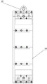
FIG. 1 is a schematic structural diagram of a horizontal double-head friction welding machine;
FIG. 2 is a schematic view of the guide bar sliding apparatus;
FIG. 3 is a schematic view of the guide rod holder structure (front view);
FIG. 4 is a schematic view of the guide rod holder structure (left side view);
FIG. 5 is a schematic structural view (front view) of the steel claw clamping and moving device;
FIG. 6 is a schematic structural view (top view) of the steel claw clamping and moving device;
FIG. 7 is a top view of the steel jaw clamping and moving device (with the steel jaw clamp removed);
FIG. 8 is a sectional view taken along line A-A in FIG. 7;
FIG. 9 is a schematic structural view (front view) of the steel claw clamp;
FIG. 10 is a schematic structural view (left side view) of the steel claw clamp;
FIG. 11 is a schematic structural view (top view) of a steel claw clamp;
FIG. 12 is a schematic view of a rotary top base;
fig. 13, a schematic view of the structure of the main gearbox.
In the figure: 1. a welder base; 2. a guide rod body; 3. a guide rod hydraulic cylinder; 4. a guide rod side slide bar; 5. a guide bar sliding device; 6. an aluminum square bar; 7. a guide rod holder; 8. a drive end plate; 9. a main gear box; 10. a steel claw; 11. the steel claw clamps the shifter; 12. a steel claw side slide bar; 13. a steel claw hydraulic cylinder; 14. a steel claw bed body; 15. a guide bar sliding body; 16. a holder clamp; 17. a pin shaft; 18. a guide rod groove; 19. supporting the side plates; 20. the guide rod protrudes the block; 21. a guide bar slide rail; 22. a guide rod slider; 23. a guide rod linear bearing; 24. fixing a nut; 25. connecting a screw rod; 26. a shaft sleeve; 27. a middle support; 28. a guide rod bearing; 29. a square through hole; 30. a steel claw sliding body; 31. a steel claw clamp; 32. a steel claw linear bearing; 33. a steel claw bulge block; 34. a reinforcing bottom plate; 35. a steel claw slide rail; 36. a steel claw slide block; 37. a double-piston oil cylinder; 38. a clamp plate; 39. a steel claw groove; 40. a support plate; 41. a fixing plate; 42. lifting lugs; 43. a lead screw; 44. a lead screw nut; 45. clamping a hand; 46. supporting the laminate; 47. erecting a support rib plate; 48. an arc-shaped surface; 49. a workpiece placing groove; 50. a gland; 51. a rotating bearing; 52. a seat shell; 53. an angle measuring device; 54. positioning the bearing; 55. a central through hole; 56. a shaft shoulder; 57. a rotating shaft seat; 58. rotating the top seat; 59. a tertiary main gear; 60. and a hollow cavity.
Detailed Description
The invention will be further described with reference to the accompanying drawings:
as shown in fig. 1-13, the horizontal double-head friction welding machine of the present invention comprises a welding machine base 1, a main gear box 9 is arranged above the welding machine base 1, a guide rod bed body 2 and a steel claw bed body 14 are respectively fixed above the welding machine base 1 on the left and right sides of the main gear box 9, a guide rod hydraulic cylinder 3 is arranged at one end above the guide rod bed body 2, a guide rod sliding device 5 is arranged between the guide rod hydraulic cylinder 3 and the main gear box 9, a steel claw hydraulic cylinder 13 is arranged at one end above the steel claw bed body 14, and a steel claw clamping and moving device 11 is arranged between the steel claw hydraulic cylinder 13 and the main gear box 9; a transmission end plate 8 is arranged at the inlet end of the main gear box 9, and a workpiece placing through hole is formed in the middle of the transmission end plate 8; the center lines of the guide rod hydraulic cylinder 3, the steel claw hydraulic cylinder 13 and the workpiece placing through hole are overlapped.
In this embodiment:
the guide rod sliding device 5 comprises a guide rod sliding body 15, a guide rod groove 18 is formed in the upper portion of the guide rod sliding body 15, a retainer clamp 16 is arranged in the guide rod groove 18, a guide rod retainer 7 is clamped in the retainer clamp 16, a pin shaft 17 is additionally arranged at the top end of the retainer clamp 16, and two ends of the pin shaft 17 are inserted into pin holes formed in the guide rod sliding body 15 on two sides of the guide rod groove 18; a guide rod sliding block 22 is arranged on the lower bottom surface of the guide rod sliding body 15, and the guide rod sliding block 22 is in sliding fit with a guide rod sliding rail 21 arranged on the guide rod lathe body 2; the upper parts of the guide rod sliding bodies 15 on the two sides of the guide rod groove 18 are respectively provided with a guide rod linear bearing 23, and the central line of the guide rod linear bearing 23 is parallel to the central line of the guide rod retainer 7; a guide rod side sliding rod 4 is arranged in the guide rod linear bearing 23, and two ends of the guide rod side sliding rod 4 are respectively fixedly connected with the guide rod lathe body 2 through connecting plates. The arrangement of the guide rod side sliding rod 4 ensures that the overturning stress of the guide rod sliding body 15 is completely eliminated and only linear motion is realized, the accuracy of a welding position is ensured, and the arrangement of the guide rod linear bearing 23 ensures that the guide rod sliding body 15 can perform accurate and low-resistance horizontal motion along a set track; during welding, the aluminum square rod 6 is placed in the guide rod holder 7, the guide rod hydraulic cylinder 3 pushes the guide rod sliding body 15 to enable the guide rod sliding body 15 to carry the guide rod holder 7 and the aluminum square rod 6 to move to a welding position, in the moving process, the sliding block is in sliding fit on the sliding rail, the guide rod side sliding rod 4 plays a role in guiding the guide rod sliding body 15, the guide rod holder 7 can rotate in the holder clamp 16, and the guide rod sliding body 15 is assisted to rotate; during upset welding, the guide rod hydraulic cylinder 3 acts to push the aluminum square rod 6 to move towards the steel claw 10, and welding is gradually completed. The width dimension of the holder clamp 16 is matched with the width dimension of the guide rod holder 7, so that the aluminum square rod 6 is ensured not to swing left and right in the welding process. And the pin shaft 17 is propped against the top end of the holder clamp 16, so that the holder clamp 16 cannot jump, and when the workpiece is welded, the pin shaft 17 is pulled out, so that the holder clamp 16 and the guide rod holder 7 are in a detachable state.
The guide rod retainer 7 comprises a plurality of connecting screw rods 25, a plurality of guide rod bearings 28 and a plurality of middle brackets 27, the periphery of each middle bracket 27 is circular, a square through hole 29 is formed in the middle of each middle bracket 27, the center line of each square through hole 29 is overlapped with the center line of each middle bracket 27, and the middle brackets 27 on the periphery of each square through hole 29 are provided with a plurality of screw rod through holes; the connecting screw 25 penetrates through the screw through hole, a pair of fixing nuts 24 are arranged on the connecting screw 25 on two sides of each middle support 27, the middle supports 27 are fixedly connected with the connecting screw 25 through the pair of fixing nuts 24, a guide rod bearing 28 is arranged on the connecting screw 25 between the fixing nuts 24 on one side of the middle supports 27 and the middle supports 27, and the outer ring of the guide rod bearing 28 exceeds the hole wall of the square through hole 29. In the working process, the aluminum square rod 6 penetrates through the square through hole 29 of the middle support 27, the outer rings of the plurality of bearings abut against the peripheral side surfaces of the aluminum square rod 6 respectively, the size of the area surrounded by the plurality of bearings is matched with the shape of the aluminum square rod 6, and the outer rings of the bearings abut against the peripheral side surfaces of the aluminum square rod 6, so that the aluminum square rod 6 can be effectively prevented from being bent and deformed in the welding process; and when the square aluminum rod 6 is driven to rotate by the transmission end plate 8, the square aluminum rod 6 drives the middle bracket 27 to rotate in the holder clamp 16.
The outer race of the rod bearing 28 extends beyond the outer peripheral edge of the intermediate bracket 27. During the welding, aluminium square bar 6 need constantly rotate, and guide rod bearing 28 outer lane surpasss middle support 27 neighboring to guide rod bearing 28 outer lane and holder anchor clamps 16's wall contact, cooperation aluminium square bar 6 that can be better is rotatory, makes aluminium square bar 6's rotation more smooth and easy, further guarantees that aluminium square bar 6 does not take place horizontal hunting among the welding process.
The guide rod bearing 28 is a needle bearing; the shaft sleeve 26 is additionally arranged between the inner ring of the guide rod bearing 28 and the connecting screw rod 25, the shaft sleeve 26 is arranged to be beneficial to better matching between the guide rod bearing 28 and the connecting screw rod 25, the damaged guide rod bearing 28 is convenient to replace, when the individual guide rod bearing 28 breaks down, the bearing can be replaced by damaging the shaft sleeve 26, the connecting screw rod 25 is guaranteed not to be damaged, and normal use of other parts is not influenced.
The steel claw clamping and moving device 11 comprises a steel claw sliding body 30, a steel claw groove 39 is formed in the front surface of the steel claw sliding body 30, a double-piston oil cylinder 37 is fixed to the upper portion of the steel claw sliding body 30 on the back of the steel claw groove 39, piston rods at two ends of the double-piston oil cylinder 37 are fixedly connected with clamp clamping plates 38 respectively, the clamp clamping plates 38 are arranged along the side wall of the steel claw groove 39, and the steel claw clamp 31 is clamped between the two clamp clamping plates 38; the bottom surfaces of the steel claw sliding bodies 30 on the two sides of the steel claw groove 39 are respectively provided with a steel claw sliding block 36, the steel claw sliding blocks 36 are in sliding fit with steel claw sliding rails 35 arranged on the steel claw bed 14, the upper parts of the steel claw sliding bodies 30 on the two sides of the steel claw groove 39 are respectively provided with a steel claw linear bearing 32, a steel claw side sliding rod 12 is arranged in the steel claw linear bearing 32, and the two ends of the steel claw side sliding rod 12 are respectively fixedly connected with the steel claw bed 14 through connecting plates. The arrangement of the steel claw side sliding rod 12 ensures that the overturning stress of the steel claw sliding body 30 is completely eliminated and only linear motion is realized, so that the accuracy of a welding position is ensured; the steel jaw linear bearing 32 ensures that the steel jaw sliding body 30 can perform accurate and low-resistance horizontal movement along a set track. In the working process, the steel claw 10 is clamped on the steel claw clamp 31 through a travelling crane, then the steel claw clamp 31 carrying the steel claw 10 is moved to a position between two clamp clamping plates 38, and the double-piston oil cylinder 37 acts to drive the clamp clamping plates 38 to clamp and fix the steel claw clamp 31 carrying the steel claw 10; firstly, the steel claw hydraulic cylinder 13 pushes the steel claw sliding body 30 to enable the steel claw sliding body 30 to carry the steel claw 10 to a welding station, then the steel claw hydraulic cylinder 13 acts again to push the steel claw sliding body 30 to carry the steel claw clamp 31 and the steel claw 10 to move towards the aluminum square rod 6 simultaneously, and the steel claw sliding body and the steel claw clamp are in upset welding with the aluminum square rod 6.
The steel claw clamp 31 comprises a supporting plate 40, supporting side plates 19 are fixed on two sides of the supporting plate 40 respectively, an upper part and a lower part between the two supporting side plates 19 are provided with an upper clamp group and a lower clamp group respectively, the upper clamp group and the lower clamp group both comprise a lead screw 43, the thread directions of the lead screw 43 from the middle to two ends are opposite, two lead screw nuts 44 are arranged on the lead screw 43, the two lead screw nuts 44 are arranged at the positions opposite to the thread directions respectively, the two lead screw nuts 44 are fixedly connected with a clamping hand 45 respectively, and two ends of the lead screw 43 are connected with the two supporting side plates 19 through fixing plates 41 respectively. When the steel claw 10 is clamped, the steel claw 10 is hung to a clamping station through a crane, the steel claw 10 is clamped in a side-standing shape, the upper part and the lower part of the steel claw 10 are respectively clamped through an upper clamp group and a lower clamp group, and two lead screw nuts 44 on a lead screw 43 relatively move by rotating the lead screw 43 to clamp the steel claw 10; the arrangement of the supporting plate 40 is matched with the upper clamp group and the lower clamp group, so that the situation that the steel claw 10 deviates from a set track in the process of welding such as upsetting is prevented, and the welding quality of a product is prevented from being influenced. One end of the screw 43 is machined to be square, and can be fastened and adjusted by a special socket wrench.
2-4 middle supporting layer plates 46 are additionally arranged between the upper clamp group and the lower clamp group, the middle supporting layer plates 46 are perpendicular to the supporting side plates 19 and the supporting plates 40, vertical supporting rib plates 47 are fixed between the middle supporting layer plates 46, and the middle supporting layer plates 46 are fixedly connected with the supporting side plates 19 on two sides through bolts. The middle supporting layer plate 46 plays a role in supporting a claw rod in the middle of the steel claw 10, plays a role in reducing the load of the upper clamp group and the lower clamp group, and assists the upper clamp group and the lower clamp group to better complete clamping action on the steel claw 10.
The lifting lug 42 is additionally arranged at the top end of the supporting plate 40, and after the steel claw 10 is clamped, the crane can move the steel claw 10 and the steel claw clamp 31 together between the two clamp clamping plates 38 by hooking the lifting lug 42.
The one side that two tong 45 are relative is arcwall face 48, and the crooked radian of arcwall face 48 and steel claw 10 phase-match make two tong 45 can be better press from both sides tightly steel claw 10.
The lower surface of the guide rod sliding body 15 is provided with a guide rod protruding block 20, the guide rod protruding block 20 is placed in a corresponding frame groove on the guide rod lathe body 2, the aluminum square rod 6 is further guaranteed to move according to a set track, and the high quality of a welding product is guaranteed; the middle position of the bottom surface of the steel claw sliding body 30 is provided with a steel claw convex block 33, the middle position of the steel claw convex block 33 is provided with a convex groove, the convex groove is communicated with a steel claw groove 39, the steel claw convex block 33 is inserted into a preset frame groove on the steel claw lathe bed 14, the steel claw 10 is further ensured to move according to a given track, the high quality of a welded product is ensured, the bottom surface of the convex groove is provided with a reinforcing bottom plate 34, and the reinforcing bottom plate 34 plays a certain supporting role for the steel claw clamp 31.
The rotary top seat 58 comprises a seat shell 52 provided with a central through hole 55, a rotary shaft seat 57 is arranged in the central through hole 55 of the seat shell 52, the central through hole 55 is in a step shape, the upper part of the rotary shaft seat 57 is arranged in the large hole end of the central through hole 55, a top seat bearing is arranged between the rotary shaft seat 57 and the inner wall of the central through hole 55, the top seat bearing is in interference fit with the inner wall of the central through hole 55, the top seat bearing is in clearance fit with the rotary shaft seat 57, a gland 50 is fixed at the top end of the seat shell 52, and the top end of the rotary shaft seat 57 penetrates through; the upper end surface of the rotating shaft seat 57 is provided with a workpiece placing groove 49, the bottom end surface of the rotating shaft seat 57 is positioned in the small hole end of the central through hole 55, and an angle measuring device 53 is fixed on the bottom end surface of the rotating shaft seat 57; the top seat bearing comprises a rotating bearing 51 and a positioning bearing 54, a shaft shoulder 56 is arranged in the middle of the rotating shaft seat 57, the rotating bearing 51 is arranged between the shaft shoulder 56 and the gland 50, and the positioning bearing 54 is arranged between the shaft shoulder 56 and the end wall of the large hole.
The gland 50 is fixedly connected with the seat shell 52 through screws, and the top end of the rotary shaft seat 57 is higher than the top surface of the gland 50. The workpiece is inserted into the workpiece placing groove 49, and the cross section of the workpiece placing groove 49 matches with the cross section of the aluminum square bar, and the workpiece drives the rotary shaft seat 57 to rotate when rotating. In the use, seat shell 52 of this device is fixed through the piston column top of bolt and guide arm pneumatic cylinder 3, the top of guide arm pneumatic cylinder 3 advances and drives work piece aluminium square bar and steel claw top, it is rotatory when work piece aluminium square bar, aluminium square bar is rotatory to drive swivel base 57 rotatory, and angle measuring device 53 gives control system with the rotatory condition record of swivel base 57 and transmission in friction welding process, calculate position feedback to the workstation in time by the computer, let operating personnel in time acquire the position of aluminium square bar, thereby make the better judgement of operating personnel finish rotatory moment, guarantee that the aluminium square bar locating position in the product is correct when the welding finishes, accord with the requirement of customer to the product. The bottom end face of the rotating shaft seat 57 is positioned in the small hole end of the central through hole 55, and the bottom end face of the rotating shaft seat 57 is not in contact with the guide rod hydraulic cylinder 3 used in cooperation with the device, so that the lower hydraulic cylinder has no influence on the rotation of the rotating shaft seat 57. The outer ring of the shoulder 56 is smaller than the inner diameter of the large hole of the central through hole 55, so that the rotary shaft seat 57 is not affected by the shoulder 56 during the rotation process. The rotating bearing 51 and the positioning bearing 54 can enable the rotating shaft seat 57 to rotate more smoothly, and can play a role in positioning the rotating shaft seat 57, so that the rotating shaft seat 57 is prevented from randomly swinging in the central through hole 55 of the seat shell 52, the loss of components is reduced, and the service life of the components is prolonged.
The shape of the workpiece placing through hole is matched with the shape of the aluminum square bar 6, the main gear box 9 is a three-stage speed reduction gear box, the last-stage gear three-stage main gear 59 is provided with a hollow shaft, the transmission end plate 8 is fixedly connected with the three-stage main gear 59 of the main gear box 9 through bolts, a hollow cavity 60 of the hollow shaft of the three-stage main gear 59 is coaxial with the workpiece placing through hole of the transmission end plate 8, a guide rod holder 7 is arranged in the hollow cavity 60 of the hollow shaft of the three-stage main gear 59, the aluminum square bar penetrates through the guide rod holder 7 in the hollow cavity 60 of the three-stage main gear 59 and is matched with the workpiece placing through hole, the rotation and the movement of the aluminum square bar are guaranteed, the aluminum square bar cannot swing, and the welding position. The driving motor acts to drive the gear to engage and transmit power, the gear drives the transmission end plate 8 to rotate, and the transmission end plate 8 drives the aluminum square rod 6 to rotate.
And (3) mounting and fixing the workpiece: firstly, an aluminum square rod 6 penetrates through a square through hole 29 of a middle support 27, a plurality of bearing outer rings are respectively abutted against the peripheral side surfaces of the aluminum square rod 6, then the aluminum square rod 6 and a guide rod holder 7 are moved into a holder clamp 16 together through a travelling crane, then a pin shaft 17 is installed, the holder clamp 16 is fixed in a guide rod groove 18, then a guide rod sliding body 15 is manually pushed to carry the aluminum square rod 6 to a welding station, a guide rod sliding block 22 is matched with a guide rod sliding rail 21 in the moving process, and in order to ensure that the aluminum square rod 6 is not bent, the number of guide rod sliding devices 5 can be 2-3; then the steel claw 10 is hung to a clamping station by a crane, two lead screw nuts 44 on the lead screw 43 relatively move by rotating the lead screw 43 to clamp the steel claw 10, then the crane moves the steel claw 10 and the steel claw clamp 31 together to a position between two clamp plates 38 in a steel claw groove 39 by hooking a lifting lug 42, the double-piston oil cylinder 37 acts to drive the clamp plates 38 to clamp and fix the steel claw clamp 31 carrying the steel claw 10, then the steel claw sliding body 30 is manually pushed to enable the steel claw sliding body 30 to carry the steel claw 10 to a welding station, and the steel claw sliding block 36 is matched with the steel claw sliding rail 35 in the moving process.
During welding, guide rod pneumatic cylinder 3 and steel claw pneumatic cylinder 13 are used in work piece aluminium square bar 6 and steel claw slip body 30 respectively, aluminium square bar 6 constantly feeds to steel claw 10 direction under the effect of guide rod pneumatic cylinder 3 among the welding process, and when aluminium square bar 6 need rotate among the welding process, driving motor action drives gear engagement transmission power, the gear drives transmission end plate 8 and rotates, transmission end plate 8 drives aluminium square bar 6 and rotates, aluminium square bar 6 drives guide rod holder 7 and rotates in holder anchor clamps 16, and aluminium square bar 6 drives the rotation axle bed and rotates, the relative seat shell of rotation axle bed rotates, supplementary aluminium square bar 6 realizes rotating, remove and the location under the top of guide rod pneumatic cylinder advances.
Claims (10)
1. The utility model provides a horizontal double-end friction welding machine, includes welding machine base (1), its characterized in that: a main gear box (9) is arranged above the welding machine base (1), a guide rod lathe bed (2) and a steel claw lathe bed (14) are respectively fixed above the welding machine base (1) on the left side and the right side of the main gear box (9), a guide rod hydraulic cylinder (3) is arranged at one end above the guide rod lathe bed (2), a guide rod sliding device (5) is arranged between the guide rod hydraulic cylinder (3) and the main gear box (9), a rotary top seat (58) is fixed at the top end of a piston column of the guide rod hydraulic cylinder (3), a steel claw hydraulic cylinder (13) is arranged at one end above the steel claw lathe bed (14), and a steel claw clamping and moving device (11) is arranged between the steel claw hydraulic cylinder (13) and the main gear; a transmission end plate (8) is arranged at the inlet end of the main gear box (9), and a workpiece placing through hole is formed in the middle of the transmission end plate (8); the guide rod hydraulic cylinder (3), the rotary top seat (58), the steel claw hydraulic cylinder (13) and the center line of the workpiece placing through hole are overlapped.
2. The horizontal double-headed friction welder according to claim 1, characterized in that: the guide rod sliding device (5) comprises a guide rod sliding body (15), a guide rod groove (18) is formed in the upper portion of the guide rod sliding body (15), a retainer clamp (16) is arranged in the guide rod groove (18), a guide rod retainer (7) is clamped in the retainer clamp (16), a pin shaft (17) is additionally arranged at the top end of the retainer clamp (16), and two ends of the pin shaft (17) are inserted into pin holes formed in the guide rod sliding body (15) on two sides of the guide rod groove (18); a guide rod sliding block (22) is arranged on the lower bottom surface of the guide rod sliding body (15), and the guide rod sliding block (22) is in sliding fit with a guide rod sliding rail (21) arranged on the guide rod lathe body; the upper parts of the guide rod sliding bodies (15) on the two sides of the guide rod groove (18) are respectively provided with a guide rod linear bearing (23), and the central line of the guide rod linear bearing (23) is parallel to the central line of the guide rod retainer (7); a guide rod side sliding rod (4) is arranged in the guide rod linear bearing (23), and two ends of the guide rod side sliding rod (4) are respectively fixedly connected with the guide rod lathe body (2) through connecting plates.
3. The horizontal double-headed friction welder according to claim 2, characterized in that: the guide rod retainer (7) comprises a plurality of connecting screw rods (25), a plurality of guide rod bearings (28) and a plurality of middle supports (27), the peripheries of the middle supports (27) are circular, square through holes (29) are formed in the middle of the middle supports (27), the center lines of the square through holes (29) are overlapped with the center line of the middle supports (27), and the middle supports (27) on the peripheries of the square through holes (29) are provided with a plurality of screw rod through holes; the connecting screw rod (25) penetrates through the screw rod through hole, a pair of fixing nuts (24) is arranged on the connecting screw rod (25) on two sides of each middle support (27), the middle support (27) is fixedly connected with the connecting screw rod (25) through the pair of fixing nuts (24), a guide rod bearing (28) is installed on the connecting screw rod (25) between the fixing nut (24) on one side of the middle support (27) and the middle support (27), and the outer ring of the guide rod bearing (28) exceeds the hole wall of the square through hole (29).
4. The horizontal double-headed friction welder according to claim 3, characterized in that: the outer ring of the guide rod bearing (28) exceeds the peripheral edge of the middle bracket (27).
5. The horizontal double-headed friction welder according to claim 1, characterized in that: the steel claw clamping and moving device (11) comprises a steel claw sliding body (30), a steel claw groove (39) is formed in the front surface of the steel claw sliding body (30), a double-piston oil cylinder (37) is fixed to the upper portion of the steel claw sliding body (30) on the back of the steel claw groove (39), piston rods at two ends of the double-piston oil cylinder (37) are fixedly connected with clamp plates (38) respectively, the clamp plates (38) are arranged along the side wall of the steel claw groove (39), and a steel claw clamp (31) is clamped between the two clamp plates (38); the bottom surfaces of the steel claw sliding bodies (30) on the two sides of the steel claw groove (39) are respectively provided with a steel claw sliding block (36), the steel claw sliding blocks (36) are in sliding fit with steel claw sliding rails (35) arranged on the steel claw bed body (14), the upper parts of the steel claw sliding bodies (30) on the two sides of the steel claw groove (39) are respectively provided with a steel claw linear bearing (32), a steel claw side sliding rod (12) is arranged in the steel claw linear bearing (32), and the two ends of the steel claw side sliding rod (12) are respectively fixedly connected with the steel claw bed body (14) through connecting plates.
6. The horizontal double-headed friction welder according to claim 5, characterized in that: steel claw anchor clamps (31) are including backup pad (40), backup pad (40) both sides are fixed with support curb plate (19) respectively, upper portion and lower part between two support curb plates (19) are equipped with anchor clamps group and lower anchor clamps group respectively, it all includes a lead screw (43) with lower anchor clamps group to go up anchor clamps group, the screw thread opposite direction to both ends setting in the middle of lead screw (43), be provided with two screw nut (44) on lead screw (43), two screw nut (44) set up respectively in screw thread opposite direction's position, and two screw nut (44) are one tong (45) of fixedly connected with respectively, lead screw (43) both ends are connected with two support curb plates (19) through fixed plate (41) respectively.
7. The horizontal double-headed friction welder according to claim 6, characterized in that: 2-4 middle supporting laminated plates (46) are additionally arranged between the upper clamp group and the lower clamp group, the middle supporting laminated plates (46) are perpendicular to the supporting side plates (19) and the supporting plates (40), vertical supporting rib plates (47) are fixed between the middle supporting laminated plates (46), and the middle supporting laminated plates (46) are fixedly connected with the supporting side plates (19) on two sides through bolts.
8. The horizontal double-headed friction welder according to claim 6, characterized in that: the top end of the supporting plate (40) is additionally provided with a lifting lug (42).
9. The horizontal double-headed friction welder according to any one of claims 6 to 8, characterized in that: the opposite surfaces of the two clamping hands (45) are arc surfaces (48), and the bending radian of the arc surfaces (48) is matched with that of the steel claw (10).
10. The horizontal double-headed friction welder according to claim 1, characterized in that: the rotary top seat (58) comprises a seat shell (52) provided with a central through hole (55), a rotary shaft seat (57) is arranged in the central through hole (55) of the seat shell (52), the central through hole (55) is in a step shape, the upper part of the rotary shaft seat (57) is arranged in the large hole end of the central through hole (55), a top seat bearing is arranged between the rotary shaft seat (57) and the inner wall of the central through hole (55), the top seat bearing is in interference fit with the inner wall of the central through hole (55), the top seat bearing is in clearance fit with the rotary shaft seat (57), a gland (50) is fixed at the top end of the seat shell (52), and the top end of the rotary shaft seat (57) penetrates through the middle through hole of the; a workpiece placing groove (49) is formed in the upper end face of the rotating shaft seat (57), the bottom end face of the rotating shaft seat (57) is located in the small hole end of the central through hole (55), and an angle measuring device (53) is fixed on the bottom end face of the rotating shaft seat (57); the top seat bearing comprises a rotating bearing (51) and a positioning bearing (54), a shaft shoulder (56) is arranged in the middle of the rotating shaft seat (57), the rotating bearing (51) is arranged between the shaft shoulder (56) and the gland (50), and the positioning bearing (54) is arranged between the shaft shoulder (56) and the end wall of the large hole.
Priority Applications (1)
| Application Number | Priority Date | Filing Date | Title |
|---|---|---|---|
| CN202020574353.3U CN212552241U (en) | 2020-04-16 | 2020-04-16 | Horizontal double-head friction welding machine |
Applications Claiming Priority (1)
| Application Number | Priority Date | Filing Date | Title |
|---|---|---|---|
| CN202020574353.3U CN212552241U (en) | 2020-04-16 | 2020-04-16 | Horizontal double-head friction welding machine |
Publications (1)
| Publication Number | Publication Date |
|---|---|
| CN212552241U true CN212552241U (en) | 2021-02-19 |
Family
ID=74610727
Family Applications (1)
| Application Number | Title | Priority Date | Filing Date |
|---|---|---|---|
| CN202020574353.3U Expired - Fee Related CN212552241U (en) | 2020-04-16 | 2020-04-16 | Horizontal double-head friction welding machine |
Country Status (1)
| Country | Link |
|---|---|
| CN (1) | CN212552241U (en) |
-
2020
- 2020-04-16 CN CN202020574353.3U patent/CN212552241U/en not_active Expired - Fee Related
Similar Documents
| Publication | Publication Date | Title |
|---|---|---|
| CN106735812B (en) | Reinforcement cage seam welder | |
| CN205184008U (en) | Pipe fitting automatic welder | |
| CN110561003A (en) | Workpiece moving, jacking, clamping and deflection welding mechanism | |
| CN204565464U (en) | A kind of rush-harvesting and rush-planting wheel rim bonding machine | |
| CN210334872U (en) | Welding platform for super-huge steel members | |
| CN102430684B (en) | Multifunctional hydraulic track forging manipulator | |
| CN202278138U (en) | Hydraulic multi-functional rail forging manipulator with nippling-lever telescoping function | |
| CN212552241U (en) | Horizontal double-head friction welding machine | |
| CN211840781U (en) | Be applied to triaxial machine of shifting of rotating member build-up welding | |
| CN211540030U (en) | Workpiece moving, jacking, clamping and deflection welding mechanism | |
| CN211220697U (en) | Novel intelligent robot equipment | |
| CN213034604U (en) | Movable maintenance device | |
| CN213224857U (en) | Robot for welding process | |
| CN212420146U (en) | Truck longitudinal beam robot welding workstation | |
| CN105439057A (en) | Workpiece turnover device | |
| CN209158004U (en) | Differential spider axle journal self-acting grinding machine | |
| CN208391301U (en) | A kind of strong production line of Two bors d's oeuveres weldering | |
| CN107263107B (en) | Automatic processing equipment for steel pipe joint | |
| CN107234207B (en) | Six mould cold mound machines retooling auxiliary machinery hand systems | |
| CN215588336U (en) | Steel construction butt welding adjusting device | |
| CN214921414U (en) | Rotary integrated all-position laser welding machine | |
| CN211332085U (en) | Drawing device suitable for beam-pumping unit motor belt pulley is dismantled | |
| CN113732683A (en) | Automatic assembly system of assembling of small pipe diameter | |
| CN217676435U (en) | Framework lifting turnover machine | |
| CN110560883B (en) | Vertical friction welding machine |
Legal Events
| Date | Code | Title | Description |
|---|---|---|---|
| GR01 | Patent grant | ||
| GR01 | Patent grant | ||
| CF01 | Termination of patent right due to non-payment of annual fee | ||
| CF01 | Termination of patent right due to non-payment of annual fee |
Granted publication date: 20210219 |