CN212478247U - Suspended ceiling structure easy to close up - Google Patents
Suspended ceiling structure easy to close up Download PDFInfo
- Publication number
- CN212478247U CN212478247U CN202022182414.4U CN202022182414U CN212478247U CN 212478247 U CN212478247 U CN 212478247U CN 202022182414 U CN202022182414 U CN 202022182414U CN 212478247 U CN212478247 U CN 212478247U
- Authority
- CN
- China
- Prior art keywords
- plate
- panel
- closing
- wall body
- top wall
- Prior art date
- Legal status (The legal status is an assumption and is not a legal conclusion. Google has not performed a legal analysis and makes no representation as to the accuracy of the status listed.)
- Active
Links
Images

Landscapes
- Finishing Walls (AREA)
Abstract
The utility model relates to a furred ceiling technical field especially relates to a furred ceiling structure of easily closing up. The suspended ceiling structure comprises a suspended ceiling plate arranged on a top wall body, wherein a closing plate is arranged between the side end of the suspended ceiling plate and a side wall body, the suspended ceiling plate comprises a central panel and a peripheral panel arranged on the side end of the central panel, the central panel is parallel to the peripheral panel, the central panel is close to the top wall body, the peripheral panel is far away from the top wall body, and the peripheral panel is connected with the central panel through a vertical frame plate; one end of the peripheral panel close to the side wall body is connected with one end of the closing plate, and the other end of the closing plate is connected with the side wall body. The utility model discloses a set up not at the center panel and the board of closing up of same height, avoided traditional closing up in the operation, the difficult problem of board installation of closing up. Then through peripheral panel and upright frame board with the space between central panel and the board of closing up seal, guaranteed the integrality and the closure of furred ceiling, effectively improved the close up roughness of the efficiency of the operation of closing up.
Description
Technical Field
The utility model relates to a furred ceiling technical field especially relates to a furred ceiling structure of easily closing up.
Background
Along with the promotion of industrial production and modularization installation in the architectural decoration field, the aesthetic property and the construction speed of interior decoration are all effectively promoted, and the decoration of furred ceiling has important influence to aesthetic property and construction speed as the important component part of interior decoration. The decoration of suspended ceilings gradually changed from the traditional installation of plasterboard to the installation of panelized suspended ceilings.
The traditional ceiling closing-in structure is usually fixed on the wall surface by a ceiling edge keel, and the decorative panel is fixed at the bottom of the edge keel and forms right-angle butt joint with the wall surface. Because the assembly space is limited, the installation difficulty of the last plate is large, and the method generally adopted is as follows: a hinge is fixed on the keel, a wood-plastic block is fixed at the other end of the hinge, a rope is tied on the wood-plastic block, a thin rope is pulled, the hinge is pulled off, and the wood-plastic block is hung on the edge-closing aluminum on the wall to be fixed. Or the mode that the hinge is broken off with fingers and thumb by the rope is improved into the mode that the hinge is broken off with fingers and thumb by the spring, for example, a lower suspended ceiling plate closing-up device and a closing-up method disclosed by the patent document with the publication number of CN110761476A relate to the technical field of decoration design, wherein the lower suspended ceiling plate closing-up device comprises a closing-up plate, a keel arranged on the closing-up plate, a functional hinge connected with the end part of the keel, a wood plastic block connected with one end of the functional hinge far away from the keel and edge-closing aluminum used for limiting the wood plastic block, the functional hinge comprises a first plate connected with the keel, a second plate connected with the wood plastic block and a rotating shaft used for connecting the first plate and the second plate, the first plate rotates around the joint with the rotating shaft, the second plate rotates around the joint with the rotating shaft, and the spring is arranged on the rotating shaft. In the closing-up process, the string or the spring is easy to clamp and is not easy to close up, the closing-up installation process is complex, the construction speed is reduced, and in case of deviation generated in installation, the attractiveness of the closing-up line of the decorative wall surface can be influenced.
SUMMERY OF THE UTILITY MODEL
The utility model aims to solve the above problem and provide a furred ceiling structure of easy binding off.
The technical scheme of the utility model for solving the problems is that, firstly, a ceiling structure with easy closing in is provided, which comprises a ceiling board arranged on the top wall, a closing plate is arranged between the side end of the ceiling board and the side wall, the ceiling board comprises a central panel and a peripheral panel arranged on the side end of the central panel, the central panel is parallel to the peripheral panel, the central panel is close to the top wall, the peripheral panel is far away from the top wall, and the peripheral panel is connected with the central panel through a vertical frame plate; the one end that peripheral panel is close to the lateral part wall body with the one end of closing up the board is connected, the other end and the lateral part wall body of closing up the board are connected, just the one side that the top wall body was kept away from to the closing up board with the peripheral panel keeps away from the one side parallel and level of top wall body.
The closing plate can be connected with the peripheral panel in any form, such as direct bonding, or a concave-convex groove is arranged on the end surface of the closing plate, and a concave-convex piece matched and clamped with the concave-convex groove is arranged on the end surface of the peripheral panel. In order to improve the stability of the installation of the suspended ceiling, the peripheral panel and the closing plate are connected through the claw piece, and the side surfaces of the closing plate and the peripheral panel are both provided with grooves; the claw piece comprises a flush plate, a vertical connecting plate and an inserting plate which are connected to form an I shape, and also comprises at least two claw hooks arranged on one surface of the flush plate far away from the inserting plate, and the claw hooks are arranged in a mirror image mode by taking the vertical connecting plate as a central shaft; two ends of the insertion plate are respectively inserted into the grooves; the claw hook is hooked with a lifting hook arranged on the top wall body.
The lifting hook can be arbitrary structure to install in the top wall body with arbitrary form, conduct the utility model discloses a preferred, the lifting hook is including setting up in the fossil fragments of top wall body, and a plurality of covers are located the fixed cover of fossil fragments, and set up in fixed cover, be used for with the second goat's horn hook that the goat's horn hook colluded.
For the convenience of adjusting the height of furred ceiling, as the utility model discloses a preferred, fossil fragments pass through a plurality of hangers and top wall connection, the hangers is including being used for accepting the couple of fossil fragments to and the jib that top wall body, the other end were equipped with screw thread portion is inserted to one end, the couple is equipped with and supplies jib screw thread portion male through-hole, screw thread portion be equipped with be used for right the nut of couple location.
In order to guarantee the horizontal installation of closing up the board, as the utility model discloses a preferred, the lateral part wall body is equipped with the installed part of making level of L shape, including parallel mount in the screed-plate of lateral part wall body and with the perpendicular mounting panel of being connected of screed-plate, close up the board face laminate in the mounting panel face just the closing up the board with the installed part of making level is connected.
As the utility model discloses a preferred, the board of closing up with the installed part of making level passes through the installation nail and connects, and lateral part wall body is equipped with the decoration panel, the decoration panel thickness is greater than the external diameter of installation nail is in order to cover the nail hole that forms when the installation nail is fixed.
As the utility model discloses a preferred, center panel includes that a plurality of sides all are equipped with the veneer of recess, all pass through between the veneer the goat's horn spare is connected, the goat's horn spare all passes through the lifting hook sets up in top wall body.
As the utility model discloses a preferred, be equipped with the second installed part of making level between upright frame board and the peripheral panel, the second installed part of making level include the second screed-plate and with the perpendicular second mounting panel of being connected of second screed-plate, the second screed-plate face with the laminating of upright frame board face is connected, the second mounting panel face with the laminating of peripheral panel face is connected.
The utility model has the advantages that:
1. the utility model discloses design traditional furred ceiling board for high-order central panel and low-order peripheral panel, design low-order closing up board simultaneously. When the closing-in plate is installed, the central panel and the closing-in plate are installed firstly, and because the central panel and the closing-in plate are not at the same height, the installation between the central panel and the closing-in plate is not influenced mutually, and the problem that the closing-in plate is difficult to install in the traditional closing-in operation is avoided. Then the space between the central panel and the closing plate is sealed by the peripheral panel and the vertical frame plate, and the integrity and the sealing performance of the suspended ceiling are ensured. The utility model discloses a mounting means of this kind of furred ceiling structure has effectively improved the binding off roughness of the efficiency of binding off operation.
2. The utility model provides a center panel forms through the concatenation of goat's horn spare for a plurality of veneers for when the center panel installation, the veneer can be directly lifted the installation on one, need not assemble the back and lift on the whole, has reduced the restriction to operating space, and the mounting means is simple, the material is simple, structural design is novel.
Drawings
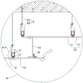
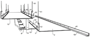
FIG. 1 is a schematic structural view of a drop ceiling construction having a readily collapsible structure;
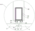
FIG. 2 is an enlarged view taken at A in FIG. 1;
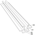
FIG. 3 is an enlarged view taken at A-1 in FIG. 2;
FIG. 4 is a schematic view of a cleat of a drop ceiling construction;
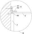
FIG. 5 is an enlarged view at B in FIG. 1;
FIG. 6 is a schematic view of an installation of a drop ceiling construction having a readily collapsible enclosure;
in the figure: the suspended ceiling board 1, the veneer 11, the central panel 12, the peripheral panel 13, the upright frame plate 14, the closing plate 2, the groove 21, the cleat piece 3, the flush plate 31, the vertical connecting plate 32, the insertion plate 33, the cleat hook 34, the hook 4, the keel 41, the fixing sleeve 42, the second cleat hook 43, the hanger 5, the hanger rod 51, the hook 52, the leveling mounting piece 6, the leveling board 61, the mounting plate 62, the mounting nail 63, the decorative panel 7, and the second leveling mounting piece 8.
Detailed Description
The following are embodiments of the present invention and the accompanying drawings are used to further describe the technical solutions of the present invention, but the present invention is not limited to these embodiments.
A ceiling structure with a readily collapsible ceiling, as shown in fig. 1: the suspended ceiling structure comprises a suspended ceiling plate 1 arranged on a top wall body, and a closing plate 2 is arranged between the side end of the suspended ceiling plate 1 and a side wall body.
In order to facilitate the installation of the closing plate 2, as shown in fig. 2 and fig. 6, in the present application, the ceiling plate 1 includes a central panel 12 and a peripheral panel 13 disposed at a side end of the central panel 12, the central panel 12 is parallel to the peripheral panel 13, the central panel 12 is close to the top wall, the peripheral panel 13 is far away from the top wall, and the peripheral panel 13 is connected to the central panel 12 through a vertical frame plate 14; the one end that peripheral panel 13 is close to the lateral part wall body is connected with the one end of closing in the board 2, and the other end and the lateral part wall body of closing in the board 2 are connected, and the one side that the top wall body was kept away from to the board 2 of closing in and the one side parallel and level that the top wall body was kept away from to peripheral panel 13.
Of course, instead of providing the peripheral panel 13, the width of the closing plate 2 may be set to be long (the horizontal direction in fig. 2 is defined as "width") such that one end of the closing plate 2 is connected to the side wall and the other end is directly connected to the center panel 12 via the vertical frame plate 14.
When installing the furred ceiling of this application, at first need installation central panel 12 and closing in board 2, because central panel 12 and closing in board 2 are not at same height, consequently the installation between the two does not influence each other. At this point, there must be a cavity between the closing plate 2 and the central panel 12, which affects the aesthetics and closure of the overall ceiling structure. Therefore, the peripheral panel 13 and the vertical frame plate 14 are installed to cover the cavity.
The center panel 12 may be installed by conventional ceiling installation.
The closing-up plate 2 and the side wall body can be installed in any form, but in order to ensure the horizontal installation of the closing-up plate 2, in this embodiment, as shown in fig. 5, the side wall body is provided with an L-shaped leveling installation member 6, which includes a leveling plate 61 installed in the side wall body in parallel and an installation plate 62 vertically connected with the leveling plate 61, the surface of the closing-up plate 2 is attached to the surface of the installation plate 62, and the closing-up plate 2 is connected with the leveling installation member 6. The closing plate 2 may be directly mounted on the mounting plate 62, or may be fixed by the mounting nail 63 after the upper plane thereof is attached to the lower plane of the mounting plate 62. The second fixing mode is stable, so the fixing is performed by the mounting nail 63 in the embodiment, but the nail hole is inevitably left after the mounting nail 63 is fixed. Therefore, in the embodiment, the side wall is provided with the decoration panel 7, and the thickness of the decoration panel 7 is larger than the outer diameter of the installation nail 63 so as to cover the nail hole formed when the installation nail 63 is fixed.
After the central panel 12 and the closing plate 2 are installed, the vertical frame plate 14 should be installed first, and then the peripheral panel 13 should be installed.
The vertical frame plate 14 can be a simple flat plate, and for the convenience of installation, the vertical frame plate 14 is designed as shown in fig. 2 and comprises an upper horizontal plate, a connecting vertical plate and a lower horizontal plate. When it is connected with central panel 12, with go up the horizontal plate with central panel 12 laminating back nailing fixed can, go up the horizontal plate and be close to the lateral part wall body for connecting the riser better, just also make and go up horizontal plate and nail and can not expose outside whole furred ceiling, more pleasing to the eye, also reduced its problem that leads to droing by the influence of external force.
Then the peripheral panel 13 is installed, the end of the peripheral panel 13 can be connected with the end of the closing plate 2 in any form, in this embodiment, as shown in fig. 3, the peripheral panel 13 and the closing plate 2 are connected through the cleat 3, and the side surfaces of the closing plate 2 and the peripheral panel 13 are both provided with a groove 21; as shown in figure 4, the cleat 3 comprises a flush plate 31, a vertical connecting plate 32 and an inserting plate 33 which are connected to form an I shape, the width of the inserting plate 33 is shorter than that of the flush plate 31, the cleat further comprises cleat hooks 34 arranged on one side of the flush plate 31 far away from the inserting plate 33, at least two cleat hooks are arranged, the cleat hooks are arranged in a mirror image mode by taking the vertical connecting plate 32 as a central shaft, and the symmetrical structure can ensure the stability of connection. During installation, the two ends of the insertion plate 33 are inserted into the grooves 21 respectively, and at this time, the leveling plate 31 just abuts against the upper planes of the closing plate 2 and the peripheral panel 13, so that the leveling of the closing plate 2 and the peripheral panel 13 is ensured. The claw hook 34 is then hooked to the hook 4 provided on the top wall. The hook 4 includes a keel 41 disposed on the top wall, a plurality of fixing sleeves 42 covering the keel 41, and a second claw hook 43 disposed on the fixing sleeves 42 and used for hooking with the claw hook 34. And fossil fragments 41 are connected with the top wall body through a plurality of hangers 5, and hangers 5 are including being used for accepting couple 52 of fossil fragments 41 to and one end inserts the top wall body, the other end is equipped with suspender 51 of screw portion, and suspender 51 inserts the one end of top wall body and can set up the inflation screw, improves the fastness of installation. The hook 52 comprises a hook mounting plate connected with the hanger rod 51 and a hook plate provided with a groove, wherein the hook mounting plate is provided with a through hole for inserting a threaded part of the hanger rod, the threaded part is provided with a nut for positioning the hook 52, the nut can be only one, and when the hook is positioned, the nut is arranged below the hook mounting plate to stop the downward movement of the hook 52. However, the hook 52 is liable to move upward by external force, so that a nut may be further provided above the hook mounting plate to stop the upward movement of the hook 52.
When the hook is installed, one end of the inserting plate 33 of the cleat piece 3 is clamped into the groove 21 at one end of the closing plate 2 far away from the side wall, and the cleat piece 3 is jacked up to be clamped into the hook 4. Then, one end of the peripheral panel 13 is engaged with the other end of the insertion plate 33 of the cleat member 3 through the concave groove 21, and then the plate surface of the peripheral panel 13 is attached to the lower horizontal plate of the vertical frame plate 14 and fixed by nailing.
When the vertical frame plate 14 is fixed to the peripheral panel 13, the lower horizontal plate can be directly nailed and fixed to the peripheral panel 13 after being bonded thereto. In direct nailing attachment, the lower horizontal plate is preferably spaced away from the side wall relative to the attachment riser (i.e. opposite to that in figure 2) and then from top to bottom so that nails are sequentially driven through the lower horizontal plate and through the perimeter panel 13, preferably without driving the nails completely through the perimeter panel 13, in a manner that covers the nail holes. Of course, as shown in fig. 2, a second leveling installation component 8 may be provided, where the second leveling installation component 8 includes a second leveling plate and a second installation plate perpendicularly connected to the second leveling plate, the second leveling plate is attached to and nailed to the vertical frame plate 14, and the second installation plate is attached to and nailed to the peripheral panel 13.
Above, just accomplished the installation of whole furred ceiling, furtherly, in order to improve the aesthetic property of furred ceiling, can also set up a decorative board again at the tip of peripheral panel 13, its shape structure does not all do the restriction.
Furthermore, since the peripheral panel 13 and the closing plate 2 are connected to each other by the horn 3 and to the top wall by the hooks 4 and hangers 5 to improve the fixing effect, the central panel 12 is usually not a single piece, comprising several single plates 11. Therefore, in the present application, the installation mode of the central panel 12 does not also adopt the connection mode of the horn 3, the hook 4 and the hanger 5, and the side surface of the single board 11 is provided with the groove 21 and then is clamped into the horn 3.
That is, when the high-level center panel is installed, a plurality of lifting hooks 4 are uniformly installed on the top wall, one claw piece 3 is firstly pushed upwards to be clamped into the lifting hooks 4, then the single plate 11 is lifted upwards to be clamped into the claw piece 3 through the groove 21, the other claw piece 3 is clamped into the groove 21 at the other end of the single plate 11, the claw piece 3 is pushed upwards to be clamped into the lifting hooks 4, and the installation of the first single plate 11 is completed; this step is repeated to complete the installation of the center panel 12.
The specific embodiments described herein are merely illustrative of the spirit of the invention. Various modifications, additions and substitutions for the specific embodiments described herein may be made by those skilled in the art without departing from the spirit of the invention or exceeding the scope of the invention as defined in the accompanying claims.
Claims (8)
1. The utility model provides a furred ceiling structure of easy binding off, is including setting up in furred ceiling board (1) of top wall body, set up between furred ceiling board (1) side and the lateral part wall body and close up board (2), its characterized in that: the suspended ceiling plate (1) comprises a central panel (12) and peripheral panels (13) arranged at the side ends of the central panel (12), the central panel (12) and the peripheral panels (13) are parallel, the central panel (12) is close to a top wall, the peripheral panels (13) are far away from the top wall, and the peripheral panels (13) are connected with the central panel (12) through vertical frame plates (14); the one end that peripheral panel (13) is close to the lateral part wall body with the one end of closing up board (2) is connected, the other end and the lateral part wall body of closing up board (2) are connected, just the one side that the top wall body was kept away from in closing up board (2) with the one side parallel and level that the top wall body was kept away from in peripheral panel (13).
2. A ceiling structure with a readily collapsible enclosure as claimed in claim 1, wherein: the peripheral panel (13) is connected with the closing plate (2) through a cleat piece (3), and grooves (21) are formed in the side faces of the closing plate (2) and the peripheral panel (13); the horn piece (3) comprises a flush plate (31), a vertical connecting plate (32) and an inserting plate (33) which are connected to form an I shape, and further comprises at least two horn hooks (34) which are arranged on one surface of the flush plate (31) far away from the inserting plate (33), and the horn hooks are arranged in a mirror image mode by taking the vertical connecting plate (32) as a central shaft; both ends of the insertion plate (33) are respectively inserted into the grooves (21); the claw hook (34) is hooked with a lifting hook (4) arranged on the top wall body.
3. A ceiling structure with a readily collapsible enclosure as claimed in claim 2, wherein: lifting hook (4) are including setting up in fossil fragments (41) of top wall body, and a plurality of covers are located fixed cover (42) of fossil fragments (41) to and set up in fixed cover (42), be used for with second goat's horn hook (43) that goat's horn hook (34) colluded.
4. A ceiling structure with a readily collapsible enclosure as claimed in claim 3, wherein: fossil fragments (41) are connected with the top wall body through a plurality of hangers (5), hangers (5) are including being used for accepting couple (52) of fossil fragments (41) to and one end insert top wall body, the other end is equipped with jib (51) of screw thread portion, couple (52) are equipped with and supply jib screw thread portion male through-hole, screw thread portion be equipped with be used for right the nut of couple (52) location.
5. A ceiling structure with a readily collapsible enclosure as claimed in claim 1, wherein: lateral wall body is equipped with leveling installed part (6) of L shape, including parallel mount in lateral wall body's screed-plate (61) and with screed-plate (61) perpendicular connection's mounting panel (62), closing up board (2) face laminate in mounting panel (62) face just closing up board (2) with leveling installed part (6) are connected.
6. An easy-to-close ceiling structure according to claim 5, wherein: the closing plate (2) is connected with the leveling installation piece (6) through installation nails (63), a decoration panel (7) is arranged on a side wall, and the thickness of the decoration panel (7) is larger than the outer diameter of the installation nails (63) so as to cover nail holes formed when the installation nails (63) are fixed.
7. A ceiling structure with a readily collapsible enclosure as claimed in claim 2, wherein: the central panel (12) comprises single plates (11) with a plurality of side faces provided with the grooves (21), the single plates (11) are connected through the horn pieces (3), and the horn pieces (3) are arranged on the top wall body through the lifting hooks (4).
8. A ceiling structure with a readily collapsible enclosure as claimed in claim 1, wherein: found to be equipped with between framed panel (14) and peripheral panel (13) second installation department of making level (8), second installation department of making level (8) include the second screed-plate and with the perpendicular second mounting panel of being connected of second screed-plate, the second screed-plate face with found the frame plate face laminating and connecting, the second mounting panel face with the laminating of peripheral panel face is connected.
Priority Applications (1)
| Application Number | Priority Date | Filing Date | Title |
|---|---|---|---|
| CN202022182414.4U CN212478247U (en) | 2020-09-29 | 2020-09-29 | Suspended ceiling structure easy to close up |
Applications Claiming Priority (1)
| Application Number | Priority Date | Filing Date | Title |
|---|---|---|---|
| CN202022182414.4U CN212478247U (en) | 2020-09-29 | 2020-09-29 | Suspended ceiling structure easy to close up |
Publications (1)
| Publication Number | Publication Date |
|---|---|
| CN212478247U true CN212478247U (en) | 2021-02-05 |
Family
ID=74449404
Family Applications (1)
| Application Number | Title | Priority Date | Filing Date |
|---|---|---|---|
| CN202022182414.4U Active CN212478247U (en) | 2020-09-29 | 2020-09-29 | Suspended ceiling structure easy to close up |
Country Status (1)
| Country | Link |
|---|---|
| CN (1) | CN212478247U (en) |
Cited By (1)
| Publication number | Priority date | Publication date | Assignee | Title |
|---|---|---|---|---|
| CN114687507A (en) * | 2022-03-02 | 2022-07-01 | 黄其红 | Ancient method mortise-tenon joint formula honeycomb furred ceiling |
-
2020
- 2020-09-29 CN CN202022182414.4U patent/CN212478247U/en active Active
Cited By (2)
| Publication number | Priority date | Publication date | Assignee | Title |
|---|---|---|---|---|
| CN114687507A (en) * | 2022-03-02 | 2022-07-01 | 黄其红 | Ancient method mortise-tenon joint formula honeycomb furred ceiling |
| CN114687507B (en) * | 2022-03-02 | 2024-02-06 | 黄其红 | Ancient method mortise and tenon type honeycomb furred ceiling |
Similar Documents
| Publication | Publication Date | Title |
|---|---|---|
| CN205557972U (en) | Reassembling type corner furred ceiling layer | |
| CN205712903U (en) | A kind of indoor facing wall mounting decoration panel and decoration panel hanging device | |
| CN212478247U (en) | Suspended ceiling structure easy to close up | |
| CN204898991U (en) | Reassembling type corner furred ceiling layer | |
| WO2015192785A1 (en) | Suspended ceiling profile | |
| CN205314449U (en) | Building decorative board dogging formula connecting device | |
| CN112049311A (en) | Ceiling structure easy to close and installation method | |
| CN111980282A (en) | Groove wood base layer mounting structure design and mounting method of special-shaped inclined plane ceiling | |
| CN209958599U (en) | Suspension type assembly structure for wood-plastic plate | |
| CN106437075B (en) | A kind of decorating structure of metope | |
| CN206397069U (en) | A kind of Fast Installation structure of two grades of furred ceiling corners lines | |
| CN109577541A (en) | Light trough and its installation method | |
| CN103277650B (en) | A kind of suspension fastener for installing and scaffold | |
| CN210887736U (en) | Ceiling assembled metal keel structure | |
| CN206337776U (en) | A kind of decorating structure of metope | |
| CN205712952U (en) | A kind of multifunctional decorative section | |
| CN214302374U (en) | Sandwich board wallboard traceless hanging piece | |
| CN204899109U (en) | Wall decoration board hang component futilely | |
| CN211037512U (en) | Assembled structure for installing veneer | |
| CN219158130U (en) | Assembled furred ceiling basic unit structure | |
| CN207974319U (en) | Blind box cover | |
| CN203348871U (en) | Suspension installation fastener and installation frame | |
| CN219638668U (en) | Flat line structure in metal door pocket | |
| CN2137686Y (en) | Plastic-resin wall-plate adapting construction | |
| CN214462186U (en) | Suspended ceiling modeling structure |
Legal Events
| Date | Code | Title | Description |
|---|---|---|---|
| GR01 | Patent grant | ||
| GR01 | Patent grant |