CN212469011U - Cleaning device for auto-parts production is used - Google Patents
Cleaning device for auto-parts production is used Download PDFInfo
- Publication number
- CN212469011U CN212469011U CN202020785246.5U CN202020785246U CN212469011U CN 212469011 U CN212469011 U CN 212469011U CN 202020785246 U CN202020785246 U CN 202020785246U CN 212469011 U CN212469011 U CN 212469011U
- Authority
- CN
- China
- Prior art keywords
- cleaning
- cleaning box
- pipe
- liquid
- box
- Prior art date
- Legal status (The legal status is an assumption and is not a legal conclusion. Google has not performed a legal analysis and makes no representation as to the accuracy of the status listed.)
- Active
Links
Images


Landscapes
- Cleaning By Liquid Or Steam (AREA)
Abstract
The utility model discloses a cleaning device for producing automobile accessories, which relates to the field of automobile accessory production and comprises a cleaning box, wherein a placing opening is arranged in the middle of the upper surface of the cleaning box; an inclined filter screen is fixedly arranged below the inner part of the cleaning box, the upper end of the filter screen is fixed on the inner wall of the right side of the cleaning box, and the lower end of the filter screen is fixed in the middle of the bottom surface of the inner part of the cleaning box; a spray pipe is fixedly arranged above the inside of the cleaning box, and a spray head is hermetically arranged on the spray pipe; has the advantages that: the filter screen is arranged to filter residues, so that the cleaning liquid is prevented from being pumped by the liquid supply pump, sprayed out from the spray head and stuck on accessories again to influence the cleaning effect; the liquid storage tank is arranged, so that the filter screen can be washed reversely at intervals, the possibility of blockage of the filter screen is reduced, and the service life is prolonged; the cleaning condition inside the cleaning box is observed in real time through the observation window, and the cleaning efficiency is convenient to improve.
Description
Technical Field
The utility model relates to an auto-parts production field especially relates to a cleaning device of auto-parts production usefulness.
Background
The automobile parts are each unit constituting the whole automobile and a product serving the automobile, the variety of the automobile parts is various, the consumption of the automobile is more and more along with the improvement of the living standard of people, the market of the automobile parts is more and more enlarged, the automobile parts manufacturer is rapidly developed in recent years, when cleaning and processing are carried out on automobile accessories in the production process, the accessories are clamped and cleaned in most prior art, the uniformity of accessory cleaning is reduced when the accessories are cleaned by the method, the cleaned liquid is not recycled, the utilization rate of water resources is reduced, and some cleaning devices adopt a cleaning liquid recycling mode, however, the cleaning liquid is not filtered, and the washed residue and dirt are easily pumped up by the liquid supply pump again and sprayed onto the automobile parts, so that the cleaning effect is influenced.
SUMMERY OF THE UTILITY MODEL
The utility model aims at providing a cleaning device of auto-parts production usefulness just for solving above-mentioned problem.
The utility model discloses a following technical scheme realizes above-mentioned purpose:
a cleaning device for automobile accessory production comprises a cleaning box, wherein a placing opening is formed in the middle of the upper surface of the cleaning box; an inclined filter screen is fixedly arranged below the inner part of the cleaning box, the upper end of the filter screen is fixed on the inner wall of the right side of the cleaning box, and the lower end of the filter screen is fixed in the middle of the bottom surface of the inner part of the cleaning box; a spray pipe is fixedly arranged above the inside of the cleaning box, and a spray head is hermetically arranged on the spray pipe; four corners of the bottom of the cleaning box are fixedly provided with supporting legs, the left side of the bottom surface of the cleaning box is hermetically provided with a drain pipe, and a first electric valve is hermetically arranged on the drain pipe; a liquid pumping pipe is hermetically arranged on the right side of the bottom surface of the cleaning box; a liquid supply pump is fixedly arranged at the bottom of the cleaning box, the lower end of the liquid pumping pipe is hermetically connected with the input end of the liquid supply pump, and a connecting pipe is hermetically arranged at the output end of the liquid supply pump; a liquid inlet pipe is hermetically arranged at the left side of the cleaning box; a liquid storage tank is fixedly arranged on the right side of the cleaning tank, a liquid return pipe is arranged at the lower end of the liquid storage tank in a sealing mode, the lower end of the liquid return pipe extends into the cleaning tank and is located below the filter screen, and a second electric valve is arranged on the liquid return pipe in a sealing mode; a liquid storage pipe is hermetically arranged at the upper end of the liquid storage tank, the upper end of the liquid storage pipe is hermetically connected with the connecting pipe, and one end of the connecting pipe, which is far away from the liquid supply pump, is hermetically connected with the spray pipe; a driving box is fixedly arranged on the left side of the cleaning box, and a driving motor is fixedly arranged below the inner part of the cleaning box; a screw rod is arranged above the inside of the cleaning box, the upper end and the lower end of the screw rod are respectively connected with the driving box through bearings, and the lower end of the screw rod extends to be fixedly connected with the output end of the driving motor; the cleaning box is characterized in that a sliding block is arranged on the screw rod, the sliding block is in threaded connection with the screw rod, a supporting rod is fixedly mounted on the sliding block, the supporting rod is divided into a horizontal section and a vertical section, the horizontal section of the supporting rod is fixedly connected with the sliding block, the vertical section of the supporting rod is arranged on the placing opening and extends to the inside of the cleaning box, and a cleaning frame is fixedly mounted at the lower end of the vertical section of the supporting rod.
Preferably: the spray pipe is annular, and the number of shower nozzles is 8 and evenly distributed on the spray pipe.
Preferably: an observation window is fixedly arranged in the middle of the front surface of the cleaning box.
Preferably: the cleaning box is characterized in that a control panel is fixedly mounted on one side of the front surface of the cleaning box, the driving motor and the liquid supply pump are respectively electrically connected with the control panel, and the first electric valve and the second electric valve are respectively electrically connected with the control panel.
Preferably: the cleaning frame is of a frame-shaped structure.
Preferably: the slider is a cuboid block, and the inner shape of the driving box corresponds to the shape of the slider.
Compared with the prior art, the beneficial effects of the utility model are as follows: the filter screen is arranged to filter residues, so that the cleaning liquid is prevented from being pumped by the liquid supply pump, sprayed out from the spray head and stuck on accessories again to influence the cleaning effect; the liquid storage tank is arranged, so that the filter screen can be reversely washed at intervals, the possibility of blockage of the filter screen is reduced, and the service life is prolonged; the cleaning condition in the cleaning box is observed in real time by arranging the observation window, so that the cleaning efficiency is improved conveniently; through the arrangement of the screw rod and the sliding block, the mechanical lifting is realized, the cleaning and the outside are separated, and the outside cleanness is ensured; the spray pipe is annular, and the spray heads are multiple, so that the cleaning effect is comprehensive.
Drawings
In order to more clearly illustrate the embodiments of the present invention or the technical solutions in the prior art, the drawings needed to be used in the description of the embodiments or the prior art will be briefly described below, it is obvious that the drawings in the following description are only some embodiments of the present invention, and for those skilled in the art, other drawings can be obtained according to these drawings without inventive exercise.
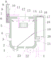
Fig. 1 is a schematic structural diagram of a cleaning device for producing auto parts.
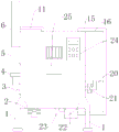
Fig. 2 is a front view of the cleaning device for producing auto parts of the present invention.
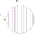
Fig. 3 is a top view of a cleaning frame of a cleaning device for producing auto parts according to the present invention.
Fig. 4 is a plan view of a nozzle of a cleaning device for automobile accessory production according to the present invention.
Fig. 5 is a working principle diagram of a cleaning device for producing auto-parts of the present invention.
The reference numerals are explained below:
1. a support leg; 2. a first electric valve; 3. a blow-off pipe; 4. a liquid inlet pipe; 5. a cleaning tank; 6. a drive box; 7. a drive motor; 8. a bearing; 9. a screw; 10. a slider; 11. a support bar; 12. a placement port; 13. a nozzle; 14. a spray head; 15. a connecting pipe; 16. a liquid storage pipe; 17. cleaning the frame; 18. a liquid storage tank; 19. filtering with a screen; 20. a liquid return pipe; 21. a second electric valve; 22. a liquid supply pump; 23. a liquid pumping pipe; 24. a control panel; 25. and (4) an observation window.
Detailed Description
In the description of the present invention, it is to be understood that the terms "central", "longitudinal", "lateral", "upper", "lower", "front", "rear", "left", "right", "vertical", "horizontal", "top", "bottom", "inner", "outer", etc., indicate orientations or positional relationships based on those shown in the drawings, and are used only for convenience in describing and simplifying the description, but not for indicating or implying that the device or element being referred to must have a particular orientation, be constructed and operated in a particular orientation, and thus are not to be construed as limiting the invention, and further that the terms "first", "second", etc., are used only for descriptive purposes and are not to indicate or imply relative importance or imply the number of technical features being referred to, whereby the features defined as "first", "second", etc., may explicitly or implicitly include one or more such features, in the description of the present invention, "a plurality" means two or more unless otherwise specified.
In the description of the present invention, it is to be noted that, unless otherwise explicitly specified or limited, the terms "mounted," "connected," and "connected" are to be construed broadly, and may be, for example, fixedly connected, detachably connected, or integrally connected; can be mechanically or electrically connected; the two elements may be directly connected or indirectly connected through an intermediate medium, or the two elements may be connected through an intermediate medium, and the specific meaning of the above terms in the present invention can be understood by those skilled in the art through specific situations.
The present invention will be further explained with reference to the accompanying drawings:
as shown in fig. 1-5, a cleaning device for producing automobile accessories comprises a cleaning box 5, wherein a placing opening 12 is formed in the middle of the upper surface of the cleaning box 5, and the placing opening 12 is used for placing automobile accessories; an inclined filter screen 19 is fixedly arranged below the inner part of the cleaning box 5, the filter screen 19 is used for filtering, the upper end of the filter screen 19 is fixed on the inner wall of the right side of the cleaning box 5, and the lower end of the filter screen 19 is fixed in the middle of the bottom surface in the cleaning box 5; a spray pipe 13 is fixedly arranged above the inside of the cleaning box 5, a spray head 14 is hermetically arranged on the spray pipe 13, and the spray head 14 is used for spraying liquid; four corners of the bottom of the cleaning box 5 are fixedly provided with supporting legs 1, the supporting legs 1 are used for supporting, the left side of the bottom surface of the cleaning box 5 is hermetically provided with a drain pipe 3, the drain pipe 3 is used for discharging residues, a first electric valve 2 is hermetically arranged on the drain pipe 3, and the first electric valve 2 is used for controlling communication; a liquid pumping pipe 23 is hermetically arranged on the right side of the bottom surface of the cleaning box 5, and the liquid pumping pipe 23 is used for connection; a liquid supply pump 22 is fixedly installed at the bottom of the cleaning box 5, the liquid supply pump 22 is used for supplying liquid, the lower end of a liquid pumping pipe 23 is hermetically connected with the input end of the liquid supply pump 22, a connecting pipe 15 is hermetically installed at the output end of the liquid supply pump 22, and the connecting pipe 15 is used for connection; a liquid inlet pipe 4 is hermetically arranged at the left side of the cleaning box 5, and the liquid inlet pipe 4 is used for feeding liquid; a liquid storage tank 18 is fixedly arranged on the right side of the cleaning tank 5, the liquid storage tank 18 is used for storing liquid, a liquid return pipe 20 is arranged at the lower end of the liquid storage tank 18 in a sealing mode, the liquid return pipe 20 is used for returning liquid, the lower end of the liquid return pipe 20 extends into the cleaning tank 5 and is located below the filter screen 19, a second electric valve 21 is arranged on the liquid return pipe 20 in a sealing mode, and the second electric valve 21 is used for controlling communication; the upper end of the liquid storage tank 18 is hermetically provided with a liquid storage pipe 16, the upper end of the liquid storage pipe 16 is hermetically connected with a connecting pipe 15, and one end of the connecting pipe 15, which is far away from the liquid supply pump 22, is hermetically connected with the spray pipe 13; a driving box 6 is fixedly arranged at the left side of the cleaning box 5, a driving motor 7 is fixedly arranged below the inner part of the cleaning box 5, and the driving motor 7 is used for driving; a screw 9 is arranged above the inside of the cleaning box 5, the upper end and the lower end of the screw 9 are respectively connected with the driving box 6 through a bearing 8, and the lower end of the screw 9 extends to be fixedly connected with the output end of the driving motor 7; the screw 9 is provided with a sliding block 10, the screw 9 and the sliding block 10 are used for moving in a matched mode, the sliding block 10 is connected with the screw 9 through threads, a supporting rod 11 is fixedly installed on the sliding block 10, the supporting rod 11 is used for supporting and connecting, the supporting rod 11 is divided into a horizontal section and a vertical section, the horizontal section of the supporting rod 11 is fixedly connected with the sliding block 10, the vertical section of the supporting rod 11 extends into the cleaning box 5 from a placing opening 12, the lower end of the vertical section of the supporting rod 11 is fixedly provided with a cleaning frame 17, and the cleaning frame 17 is used for containing automobile accessories; the spray pipes 13 are annular, and the number of the spray heads 14 is 8 and the spray heads are uniformly distributed on the spray pipes 13; an observation window 25 is fixedly arranged in the middle of the front surface of the cleaning box 5, and the observation window 25 is used for facilitating real-time observation; a control panel 24 is fixedly installed on one side of the front surface of the cleaning box 5, the control panel 24 is used for facilitating operation and control, the driving motor 7 and the liquid supply pump 22 are respectively electrically connected with the control panel 24, and the first electric valve 2 and the second electric valve 21 are respectively electrically connected with the control panel 24; the cleaning frame 17 is a frame-shaped structure; the slider 10 is a rectangular parallelepiped block, and the inside shape of the drive case 6 corresponds to the shape of the slider 10.
The working principle is as follows: when the automobile parts are cleaned, an external power supply supplies power, the control panel 24 is operated for control, the driving motor 7 is started to drive the screw rod 9 to rotate, the sliding block 10 moves upwards, the sliding block 10 drives the placing frame to move upwards out of the placing opening 12 through the supporting rod 11, the automobile parts to be cleaned are placed on the placing frame, the driving motor 7 is started to rotate reversely, the sliding block 10 moves downwards, so that the placing frame moves downwards, and the placing frame position and the subsequent cleaning state can be observed in real time through the observation window 25; connecting a liquid inlet pipe 4 with an external pipeline, adding cleaning liquid into a cleaning box 5, starting a liquid supply pump 22 to pump the cleaning liquid, supplying the cleaning liquid to a spray pipe 13 through a connecting pipe 15, carrying out liquid spraying washing on automobile parts placed in a frame by the cleaning liquid from a spray head 14, and simultaneously enabling the cleaning liquid in the connecting pipe 15 to enter a liquid storage box 18 from a liquid storage pipe 16; the washing liquid after washing falls in cleaning box 5 bottom, filter through filter screen 19 and draw through feed pump 22 once more and use, the residue landing in cleaning box 5 bottom left side that is filtered out by filter screen 19, wash after a period, can open second electric valve 21, the washing liquid in the liquid reserve tank 18 flows into cleaning box 5 bottom right side, produce the impulsive force left to filter screen 19, wash away the residue on the filter screen 19, then second electric valve 21 closes, liquid reserve tank 18 continues the stock solution and waits for next action, after the washing is accomplished, start driving motor 7 and drive screw 9 and rotate, slider 10 moves up, slider 10 passes through bracing piece 11 and drives and place the frame and move out and place mouthful 12, can take out the automobile parts who washs, then open first electric valve 2, it can to discharge the left residue in cleaning box 5 bottom.
Having shown and described the basic principles, essential features and advantages of the invention, it should be understood by those skilled in the art that the present invention is not limited by the foregoing embodiments, which are merely illustrative, but rather are intended to cover various changes and modifications within the spirit and scope of the invention as defined by the appended claims.
Claims (6)
1. The utility model provides a cleaning device of auto-parts production usefulness which characterized in that: comprises a cleaning box (5), wherein a placing opening (12) is arranged in the middle of the upper surface of the cleaning box (5); an inclined filter screen (19) is fixedly arranged below the inner part of the cleaning box (5), the upper end of the filter screen (19) is fixed on the inner wall of the right side of the cleaning box (5), and the lower end of the filter screen (19) is fixed in the middle of the bottom surface of the inner part of the cleaning box (5); a spray pipe (13) is fixedly arranged above the inside of the cleaning box (5), and a spray head (14) is hermetically arranged on the spray pipe (13); four corners of the bottom of the cleaning box (5) are fixedly provided with supporting legs (1), the left side of the bottom surface of the cleaning box (5) is hermetically provided with a sewage discharge pipe (3), and the sewage discharge pipe (3) is hermetically provided with a first electric valve (2); a liquid pumping pipe (23) is hermetically arranged on the right side of the bottom surface of the cleaning box (5); a liquid supply pump (22) is fixedly installed at the bottom of the cleaning box (5), the lower end of the liquid pumping pipe (23) is hermetically connected with the input end of the liquid supply pump (22), and a connecting pipe (15) is hermetically installed at the output end of the liquid supply pump (22); a liquid inlet pipe (4) is hermetically arranged at the left side of the cleaning box (5); a liquid storage tank (18) is fixedly mounted on the right side of the cleaning tank (5), a liquid return pipe (20) is mounted at the lower end of the liquid storage tank (18) in a sealing mode, the lower end of the liquid return pipe (20) extends into the cleaning tank (5) and is located below the filter screen (19), and a second electric valve (21) is mounted on the liquid return pipe (20) in a sealing mode; a liquid storage pipe (16) is hermetically mounted at the upper end of the liquid storage tank (18), the upper end of the liquid storage pipe (16) is hermetically connected with the connecting pipe (15), and one end, far away from the liquid supply pump (22), of the connecting pipe (15) is hermetically connected with the spray pipe (13); a driving box (6) is fixedly installed on the left side of the cleaning box (5), and a driving motor (7) is fixedly installed below the inner part of the cleaning box (5); a screw rod (9) is arranged above the inside of the cleaning box (5), the upper end and the lower end of the screw rod (9) are respectively connected with the driving box (6) through a bearing (8), and the lower end of the screw rod (9) extends to be fixedly connected with the output end of the driving motor (7); a sliding block (10) is arranged on the screw rod (9), and the sliding block (10) is clamped in the driving box (6) to move up and down; slider (10) with screw rod (9) pass through threaded connection, fixed mounting has bracing piece (11) on slider (10), bracing piece (11) divide into horizontal segment and vertical section two parts, the horizontal segment of bracing piece (11) with slider (10) fixed connection, the vertical section of bracing piece (11) is followed place mouthful (12) and extend to inside clean case (5), the vertical section lower extreme fixed mounting of bracing piece (11) has washing frame (17).
2. The cleaning device for the production of automobile accessories according to claim 1, wherein: the spray pipes (13) are annular, and the spray heads (14) are 8 and are uniformly distributed on the spray pipes (13).
3. The cleaning device for the production of automobile accessories according to claim 1, wherein: an observation window (25) is fixedly arranged in the middle of the front surface of the cleaning box (5).
4. The cleaning device for the production of automobile accessories according to claim 1, wherein: cleaning box (5) front surface one side fixed mounting have control panel (24), driving motor (7) with feed pump (22) respectively with control panel (24) electric connection, first electrovalve (2) with second electrovalve (21) respectively with control panel (24) electric connection.
5. The cleaning device for the production of automobile accessories according to claim 1, wherein: the cleaning frame (17) is of a frame-shaped structure.
6. The cleaning device for the production of automobile accessories according to claim 1, wherein: the slider (10) is in a cuboid block shape, and the inner shape of the driving box (6) corresponds to the shape of the slider (10).
Priority Applications (1)
| Application Number | Priority Date | Filing Date | Title |
|---|---|---|---|
| CN202020785246.5U CN212469011U (en) | 2020-05-13 | 2020-05-13 | Cleaning device for auto-parts production is used |
Applications Claiming Priority (1)
| Application Number | Priority Date | Filing Date | Title |
|---|---|---|---|
| CN202020785246.5U CN212469011U (en) | 2020-05-13 | 2020-05-13 | Cleaning device for auto-parts production is used |
Publications (1)
| Publication Number | Publication Date |
|---|---|
| CN212469011U true CN212469011U (en) | 2021-02-05 |
Family
ID=74459747
Family Applications (1)
| Application Number | Title | Priority Date | Filing Date |
|---|---|---|---|
| CN202020785246.5U Active CN212469011U (en) | 2020-05-13 | 2020-05-13 | Cleaning device for auto-parts production is used |
Country Status (1)
| Country | Link |
|---|---|
| CN (1) | CN212469011U (en) |
Cited By (1)
| Publication number | Priority date | Publication date | Assignee | Title |
|---|---|---|---|---|
| CN115156152A (en) * | 2022-07-08 | 2022-10-11 | 广东绿菜园膳食管理有限公司 | Intelligent automatic cleaning device and cleaning method for agricultural products |
-
2020
- 2020-05-13 CN CN202020785246.5U patent/CN212469011U/en active Active
Cited By (1)
| Publication number | Priority date | Publication date | Assignee | Title |
|---|---|---|---|---|
| CN115156152A (en) * | 2022-07-08 | 2022-10-11 | 广东绿菜园膳食管理有限公司 | Intelligent automatic cleaning device and cleaning method for agricultural products |
Similar Documents
| Publication | Publication Date | Title |
|---|---|---|
| CN212469011U (en) | Cleaning device for auto-parts production is used | |
| CN109719102B (en) | Tray cleaning device | |
| CN209255364U (en) | A kind of semiconductor wafer acid dip pickle | |
| CN210450049U (en) | Multifunctional cleaning device | |
| CN210304763U (en) | Enzyme-labeled reaction plate cleaning device | |
| CN212285025U (en) | Optical glass ultrasonic cleaning device | |
| CN209816313U (en) | A impurity cleaning device for auto-parts's electrophoresis equipment | |
| CN211519463U (en) | Intelligent network car washer | |
| CN211676378U (en) | Rectifying tower with self-cleaning function | |
| CN209732549U (en) | A grape belt cleaning device for grape wine preparation | |
| CN216323645U (en) | Cleaning device for machining of mechanical bearing | |
| CN210729246U (en) | Laborsaving storage silo convenient to wash | |
| CN215715760U (en) | Automatically cleaning type regulation pump station is with novel water tank | |
| CN220738691U (en) | Printed circuit board belt cleaning device | |
| CN213586463U (en) | Etching machine of circuit board production usefulness | |
| CN216965460U (en) | Solar photovoltaic power generation and electric precipitation device | |
| CN218932566U (en) | Blank cloth feeding structure with cleaning structure for towel production and processing | |
| CN218328304U (en) | Inside self-cleaning device of integrative lampblack absorber of oil smoke purification | |
| CN215613694U (en) | Automatic ultrasonic cleaning machine | |
| CN218945759U (en) | Cleaning device for mechanical parts | |
| CN220497157U (en) | Lifting ultrasonic cleaner | |
| CN218797964U (en) | Steam washing device of reaction kettle | |
| CN211412860U (en) | Rotary cleaning machine | |
| CN219851026U (en) | Physical cleaning device for water treatment | |
| CN216369391U (en) | Material barrel belt cleaning device for chemical engineering |
Legal Events
| Date | Code | Title | Description |
|---|---|---|---|
| GR01 | Patent grant | ||
| GR01 | Patent grant | ||
| CP01 | Change in the name or title of a patent holder |
Address after: 452470 west section of Yujing Avenue, Dengfeng Industrial Cluster District, Zhengzhou City, Henan Province Patentee after: Zhengzhou Xinsheng Surface Technology Co.,Ltd. Address before: 452470 west section of Yujing Avenue, Dengfeng Industrial Cluster District, Zhengzhou City, Henan Province Patentee before: Zhengzhou Xinsheng Auto Parts Co.,Ltd. |
|
| CP01 | Change in the name or title of a patent holder |