CN212456647U - Movable lighting device - Google Patents
Movable lighting device Download PDFInfo
- Publication number
- CN212456647U CN212456647U CN202021376048.XU CN202021376048U CN212456647U CN 212456647 U CN212456647 U CN 212456647U CN 202021376048 U CN202021376048 U CN 202021376048U CN 212456647 U CN212456647 U CN 212456647U
- Authority
- CN
- China
- Prior art keywords
- gear
- rack
- support column
- supporting column
- lighting device
- Prior art date
- Legal status (The legal status is an assumption and is not a legal conclusion. Google has not performed a legal analysis and makes no representation as to the accuracy of the status listed.)
- Expired - Fee Related
Links
Images

Abstract
The utility model discloses a mobilizable lighting device, including first support column, mounting panel, second support column and connecting block, the second support column is installed at the top of mounting panel, the handle is installed to one side of second support column, the inside of second support column is provided with elevation structure, elevation structure is including slider, spout, gear and rack, the inside at the second support column is installed to the gear, the one end and the handle fixed connection of gear, the rack is installed to the one end of gear, the slider is installed to the one end of rack, the spout is installed to the one end of slider. The utility model discloses an install the handle in one side of second support column, rotate the handle, drive gear revolve, constitute the meshing structure between gear and the rack, the gear drives the rack and rises or descend, utilizes slider and spout cooperation simultaneously to drive first support column and make progress or lower height-adjusting, can adjust the height of light source according to workman's needs.
Description
Technical Field
The utility model relates to the field of lighting technology, specifically be mobilizable lighting device.
Background
With the continuous development and progress of society, the construction equipment of building engineering is also being improved gradually, and building construction usually carries out the operation outdoors, in order to arrive at a project date, usually need to be under construction day and night continuously in order to accelerate the engineering progress, and during construction at night, often need to use a kind of building lighting apparatus, and building lighting utilizes natural light or artificial light source, illuminates the building construction place:
traditional lighting device, because when using, the height-adjusting of being not convenient for, can't adapt to the demand of different places to the light source height.
SUMMERY OF THE UTILITY MODEL
An object of the utility model is to provide a mobilizable lighting device to solve the problem of the height-adjusting of being not convenient for that proposes among the above-mentioned background art.
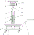
In order to achieve the above object, the utility model provides a following technical scheme: mobilizable lighting device, including first support column, mounting panel, second support column and connecting block, the second support column is installed at the top of mounting panel, the handle is installed to one side of second support column, the inside of second support column is provided with elevation structure, elevation structure includes slider, spout, gear and rack, the gear is installed in the inside of second support column, the one end and the handle fixed connection of gear, the rack is installed to the one end of gear, the slider is installed to the one end of rack, the spout is installed to the one end of slider, first support column is installed at the top of second support column, the connecting block is installed at the top of first support column, and the lamp shade is installed at the top of connecting block, the internally mounted of lamp shade has the light body, the outside of light body is provided with heat radiation structure, solar cell panel is installed at the top of lamp shade, the handrail is installed to one side of mounting panel, the universal wheel is all installed to four corners of mounting panel bottom, the battery is all installed to the inside of mounting panel.
Preferably, the heat radiation structure is including heat dissipation fan, heat conduction material, ventilation louvre and fin, the ventilation louvre evenly sets up the both sides at the lamp shade, the heat conduction material is installed to the one end of ventilation louvre, the heat dissipation fan is installed to one side of heat conduction material, the fin is installed to the other end of ventilation louvre.
Preferably, the radiating fins are arranged at equal intervals at two ends of the connecting block, and the radiating fins are symmetrically distributed about the center line of the lampshade.
Preferably, one end of the sliding groove is fixedly connected with the inner side wall of the second supporting column, and a sliding structure is formed between the sliding groove and the sliding block.
Preferably, the gear and the rack are in the same plane, and a meshing structure is formed between the gear and the rack.
Preferably, the lampshade connecting blocks are perpendicular to each other, and a rotating structure is formed between the lampshade and the connecting blocks.
Compared with the prior art, the beneficial effects of the utility model are that:
1. the handle is arranged on one side of the second support column, the handle is rotated to drive the gear to rotate, a meshing structure is formed between the gear and the rack, the gear drives the rack to ascend or descend, and meanwhile, the sliding block is matched with the sliding groove, so that the first support column is driven to adjust the height upwards or downwards, and the height of the light source can be adjusted according to the requirement of workers;
2. the radiating fins are arranged at the two ends of the lampshade, so that the radiating area of the surface of the lampshade can be increased, heat generated by the illuminating lamp body is conducted to the lampshade by utilizing the heat conducting material, and then the heat is radiated by utilizing the matching of the radiating fan and the ventilation and radiating holes, so that the illuminating lamp body is prevented from being damaged due to overheating, and the service life of the device is prolonged;
3. install solar cell panel through the top at the lamp shade, when the sunlight was sufficient daytime, solar cell panel utilized the photovoltaic controller to turn into the electric energy with light energy, stored the electric energy in the inside of battery, need use the light source messenger when night, and the battery can carry out the power supply of certain time to the device, improves the efficiency of construction.
Drawings
Fig. 1 is a schematic front view of a cross-sectional structure of the present invention;
FIG. 2 is a schematic view of the side view of the present invention;
fig. 3 is a schematic view of the lifting structure of the present invention;
fig. 4 is an enlarged schematic structural diagram of a in fig. 2 according to the present invention.
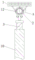
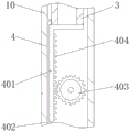
In the figure: 1. a solar panel; 2. a heat dissipation structure; 201. a heat dissipation fan; 202. a thermally conductive material; 203. ventilating and radiating holes; 204. a heat sink; 3. a first support column; 4. a lifting structure; 401. a slider; 402. a chute; 403. a gear; 404. a rack; 5. a handle; 6. mounting a plate; 7. a universal wheel; 8. a storage battery; 9. a handrail; 10. a second support column; 11. connecting blocks; 12. a lamp shade; 13. light body.
Detailed Description
The technical solutions in the embodiments of the present invention will be described clearly and completely with reference to the accompanying drawings in the embodiments of the present invention, and it is obvious that the described embodiments are only some embodiments of the present invention, not all embodiments. Based on the embodiments in the present invention, all other embodiments obtained by a person skilled in the art without creative work belong to the protection scope of the present invention.
Referring to fig. 1-4, the present invention provides an embodiment: the movable lighting device comprises a first supporting column 3, a mounting plate 6, a second supporting column 10 and a connecting block 11, wherein the second supporting column 10 is mounted at the top of the mounting plate 6, a handle 5 is mounted on one side of the second supporting column 10, a lifting structure 4 is arranged inside the second supporting column 10, the lifting structure 4 comprises a sliding block 401, a sliding groove 402, a gear 403 and a rack 404, the gear 403 is mounted inside the second supporting column 10, one end of the gear 403 is fixedly connected with the handle 5, one end of the gear 403 is provided with the rack 404, one end of the rack 404 is provided with the sliding block 401, one end of the sliding block 401 is provided with the sliding groove 402, one end of the sliding groove 402 is fixedly connected with the inner side wall of the second supporting column 10, the sliding groove 402 and the sliding block 401 form a sliding structure, the gear 403 and the rack 404 are on the;
the handle 5 is rotated to drive the gear 403 to rotate, a meshing structure is formed between the gear 403 and the rack 404, the gear 403 drives the rack 404 to ascend or descend, and meanwhile, the sliding block 401 is matched with the sliding groove 402, so that the first support column 3 is driven to adjust the height upwards or downwards, and the height of the light source can be adjusted according to the requirement of a worker;
the top of the second support column 10 is provided with a first support column 3, the top of the first support column 3 is provided with a connecting block 11, the top of the connecting block 11 is provided with a lampshade 12, the connecting blocks 11 of the lampshade 12 are mutually vertical, and a rotating structure is formed between the lampshade 12 and the connecting block 11;
the lamp comprises a lampshade 12, an illuminating lamp body 13 is arranged inside the lampshade 12, a heat dissipation structure 2 is arranged on the outer side of the illuminating lamp body 13, the heat dissipation structure 2 comprises a heat dissipation fan 201, a heat conduction material 202, a ventilation heat dissipation hole 203 and heat dissipation fins 204, the ventilation heat dissipation hole 203 is uniformly arranged on two sides of the lampshade 12, the heat conduction material 202 is arranged at one end of the ventilation heat dissipation hole 203, the heat dissipation fan 201 is arranged on one side of the heat conduction material 202, the type of the heat dissipation fan 201 can be SD-2010, the input end of the heat dissipation fan 201 is electrically connected with the output end of a control panel, the heat dissipation fins 204 are arranged at the other end of the ventilation heat dissipation hole 203, the heat dissipation;
when the lamp is used, a large amount of heat is generated by the illuminating lamp body 13, the heat generated by the illuminating lamp body 13 is conducted to the lampshade 12 by the heat conduction material 202, meanwhile, the contact area between the surface of the lampshade 12 and the air can be increased by the radiating fins 204, and then the heat generated by the illuminating lamp body 13 is radiated by the cooperation of the radiating fan 201 and the ventilation and radiation holes 203, so that the illuminating lamp body 13 is prevented from being damaged due to overheating, and the service life of the device is prolonged;
the solar cell panel 1 is mounted at the top of the lampshade 12, the handrail 9 is mounted at one side of the mounting plate 6, the universal wheels 7 are mounted at four corners of the bottom of the mounting plate 6, and the storage battery 8 is mounted in the mounting plate 6;
when sunlight is sufficient daytime, the solar cell panel 1 utilizes the photovoltaic controller to convert light energy into electric energy, stores the electric energy in the inside of the storage battery 8, needs to use a light source to make night, and the storage battery 8 can supply power to the device for a certain time, thereby improving the construction efficiency and saving energy sources.
The working principle is as follows: when the device is used, an external power supply is adopted, firstly, the device is moved to a required position through the universal wheels 7 by holding the handrail 9, and in daytime, the solar cell panel 1 converts light energy into electric energy through the photovoltaic controller, and the electric energy is stored in the storage battery 8 and can be used for a certain time;
then, the handle 5 is shaken by hands to drive the gear 403 to rotate, the gear 403 rotates to drive the rack 404 to ascend and descend, and meanwhile, the sliding block 401 is matched with the sliding groove 402, so that the first support column 3 is driven to adjust the height upwards or downwards, and the height of the light source can be adjusted according to the requirements of workers;
finally, when the device uses, light body 13 can produce a large amount of heats, when using, utilize heat conduction material 202 to lead the heat that light body 13 produced to lamp shade 12, fin 204 can increase the area of contact of lamp shade 12 surface and air simultaneously, recycle heat dissipation fan 201 and the cooperation of ventilation and heat dissipation hole 203, distribute away the heat that light body 13 produced, avoid light body 13 overheated and damage, finally accomplish the device's work.
Although the present invention has been described in detail with reference to the foregoing embodiments, it will be apparent to those skilled in the art that modifications may be made to the embodiments or portions thereof without departing from the spirit and scope of the invention.
Claims (6)
1. Mobilizable lighting device, including first support column (3), mounting panel (6), second support column (10) and connecting block (11), its characterized in that: the lamp holder is characterized in that a second supporting column (10) is installed at the top of the mounting plate (6), a handle (5) is installed on one side of the second supporting column (10), a lifting structure (4) is arranged inside the second supporting column (10), the lifting structure (4) comprises a sliding block (401), a sliding groove (402), a gear (403) and a rack (404), the gear (403) is installed inside the second supporting column (10), one end of the gear (403) is fixedly connected with the handle (5), a rack (404) is installed at one end of the gear (403), the sliding block (401) is installed at one end of the rack (404), the sliding groove (402) is installed at one end of the sliding block (401), a first supporting column (3) is installed at the top of the second supporting column (10), a connecting block (11) is installed at the top of the first supporting column (3), and a lampshade (12) is installed at the top of the connecting block (11), the utility model discloses a solar street lamp, including lamp shade (12), the internally mounted of lamp shade (12) has light body (13), the outside of light body (13) is provided with heat radiation structure (2), solar cell panel (1) are installed at the top of lamp shade (12), handrail (9) are installed to one side of mounting panel (6), universal wheel (7) are all installed to four corners of mounting panel (6) bottom, battery (8) are all installed to the inside of mounting panel (6).
2. The movable lighting device of claim 1, wherein: heat radiation structure (2) are including heat dissipation fan (201), heat conduction material (202), ventilation louvre (203) and fin (204), ventilation louvre (203) evenly sets up the both sides at lamp shade (12), heat conduction material (202) are installed to the one end of ventilation louvre (203), heat dissipation fan (201) is installed to one side of heat conduction material (202), fin (204) are installed to the other end of ventilation louvre (203).
3. The movable lighting device of claim 2, wherein: the radiating fins (204) are arranged at two ends of the connecting block (11) at equal intervals, and the radiating fins (204) are symmetrically distributed around the center line of the lampshade (12).
4. The movable lighting device of claim 1, wherein: one end of the sliding groove (402) is fixedly connected with the inner side wall of the second supporting column (10), and a sliding structure is formed between the sliding groove (402) and the sliding block (401).
5. The movable lighting device of claim 1, wherein: the gear (403) and the rack (404) are in the same plane, and a meshing structure is formed between the gear (403) and the rack (404).
6. The movable lighting device of claim 1, wherein: the lampshade and lamp shade connecting block (12) is perpendicular to the connecting block (11), and a rotating structure is formed between the lampshade (12) and the connecting block (11).
Priority Applications (1)
| Application Number | Priority Date | Filing Date | Title |
|---|---|---|---|
| CN202021376048.XU CN212456647U (en) | 2020-07-14 | 2020-07-14 | Movable lighting device |
Applications Claiming Priority (1)
| Application Number | Priority Date | Filing Date | Title |
|---|---|---|---|
| CN202021376048.XU CN212456647U (en) | 2020-07-14 | 2020-07-14 | Movable lighting device |
Publications (1)
| Publication Number | Publication Date |
|---|---|
| CN212456647U true CN212456647U (en) | 2021-02-02 |
Family
ID=74484511
Family Applications (1)
| Application Number | Title | Priority Date | Filing Date |
|---|---|---|---|
| CN202021376048.XU Expired - Fee Related CN212456647U (en) | 2020-07-14 | 2020-07-14 | Movable lighting device |
Country Status (1)
| Country | Link |
|---|---|
| CN (1) | CN212456647U (en) |
-
2020
- 2020-07-14 CN CN202021376048.XU patent/CN212456647U/en not_active Expired - Fee Related
Similar Documents
| Publication | Publication Date | Title |
|---|---|---|
| CN206708978U (en) | A kind of Novel LED street lamp | |
| CN210637953U (en) | Solar integrated heat dissipation LED street lamp | |
| CN207637009U (en) | A kind of solar energy electronic message board | |
| CN212273879U (en) | Solar street lamp convenient to maintain | |
| CN212456647U (en) | Movable lighting device | |
| CN213810379U (en) | Simple traffic lighting management device | |
| CN206656280U (en) | A kind of outdoor high-power LED street lamp | |
| CN210921182U (en) | Solar lighting device for electric power engineering | |
| CN211875723U (en) | Lighting device for building construction with good heat dissipation effect | |
| CN202303134U (en) | Independent full-automatic garden solar LED (Light-Emitting Diode) lamp | |
| CN210860916U (en) | Solar energy type landscape lighting device | |
| CN213810377U (en) | Solar street lamp capable of adjusting light source position | |
| CN210717285U (en) | Sealed outdoor LED lamp convenient to heat dissipation | |
| CN210424824U (en) | Solar street lamp convenient to installation | |
| CN210179493U (en) | Telescopic solar street lamp | |
| CN206637373U (en) | A kind of Projecting Lamp with emergency power supply illumination | |
| CN220870778U (en) | Solar street lamp | |
| CN215892208U (en) | Solar street lamp heat radiation structure | |
| CN216924223U (en) | Energy-saving city street lamp based on solar panel | |
| CN215982314U (en) | Lighting device with heat dissipation function | |
| CN203336448U (en) | Solar lighting lamp and community lighting system | |
| CN214369596U (en) | High-efficient radiating projecting lamp is used in stadium | |
| CN214332536U (en) | Energy-saving lighting device for road | |
| CN213146233U (en) | Projecting lamp that has heat radiation structure convenient to angle is shone in regulation | |
| CN211526298U (en) | Lifting type solar street lamp |
Legal Events
| Date | Code | Title | Description |
|---|---|---|---|
| GR01 | Patent grant | ||
| GR01 | Patent grant | ||
| CF01 | Termination of patent right due to non-payment of annual fee |
Granted publication date: 20210202 Termination date: 20210714 |
|
| CF01 | Termination of patent right due to non-payment of annual fee |