CN212416440U - Auxiliary disinfection box for oral cavity - Google Patents
Auxiliary disinfection box for oral cavity Download PDFInfo
- Publication number
- CN212416440U CN212416440U CN202020605635.5U CN202020605635U CN212416440U CN 212416440 U CN212416440 U CN 212416440U CN 202020605635 U CN202020605635 U CN 202020605635U CN 212416440 U CN212416440 U CN 212416440U
- Authority
- CN
- China
- Prior art keywords
- disinfection
- bin
- cleaning
- box
- switch
- Prior art date
- Legal status (The legal status is an assumption and is not a legal conclusion. Google has not performed a legal analysis and makes no representation as to the accuracy of the status listed.)
- Active
Links
Images



Abstract
An auxiliary disinfection box for oral cavity belongs to the technical field of medical instruments. The technical scheme of the utility model is that: including box body frame, disinfection storehouse, washing storehouse, filth collection storehouse and disinfectant box, characterized by disinfection storehouse top has set up the disinfection switch that is connected with high ozone ultraviolet ray disinfection lamp, the washing storehouse has installed the washing cang gai through the hinge B connection, right side fixed mounting has been washd a drive motor, the opening department has set up the circular disinfection sponge that has the round hole between the washing, set up the filth in the filth collection storehouse and collected the drawer, the utility model discloses it is multiple functional, convenient to use, medical staff can in time wash and disinfect isolation filler and powder accent sword after finishing nest hole filling, can in time carry out next operation, have alleviateed medical staff's the work degree of difficulty.
Description
The technical field is as follows:
the utility model belongs to the technical field of medical apparatus, specifically say and an oral cavity is with supplementary disinfection box.
Background art: at present, tools such as various resin fillers and powder adjusting knives are needed when the cavities are filled in stomatology clinically, and due to the operational requirements and the uniqueness of the instruments, the fillers and the adjusting knives are high in use frequency and cannot be cleaned and disinfected in time after being used every time, so that the trouble of medical staff in the stomatology is caused.
The invention content is as follows: the utility model aims at providing a nursing medicine feeder for solving the problems in the prior art.
In order to achieve the above object, the utility model provides a following technical scheme:
an auxiliary disinfection box for oral cavity comprises a box body frame, a disinfection bin, a cleaning bin, a dirt collecting bin and a disinfectant box, and is characterized in that the box body frame is composed of the disinfection bin, the cleaning bin, the dirt collecting bin and the disinfectant box, the disinfection bin is positioned above the cleaning bin, the cleaning bin is connected with the dirt collecting bin through a net-shaped partition plate, the disinfectant box is positioned at the upper right of the box body frame, the disinfection bin is connected with a disinfection bin cover through a hinge, the disinfection bin is divided into an aseptic bin A and an aseptic bin B through a partition, a high ozone ultraviolet disinfection lamp is respectively arranged in the aseptic bin A and the aseptic bin B, a disinfection switch connected with the high ozone ultraviolet disinfection lamp is arranged above the disinfection bin, the cleaning bin is connected with the cleaning bin cover through a hinge B, four cleaning rooms are arranged in the cleaning bin, the cleaning room is internally provided with a reticular rotary drum which is supported in the cleaning room through a U-shaped support, a cleaning brush is arranged in the reticular rotary drum, the right side of the cleaning room is fixedly provided with a driving motor which is connected with the reticular rotary drum through a rotor, the opening of the cleaning room is provided with a circular disinfection sponge with a round hole, the circular disinfection sponge and the reticular rotary drum are on the same horizontal line, the circular disinfection sponge is connected with a disinfection solution box through a disinfection solution pipe, the surface of the cleaning room is provided with a cleaning switch and a disinfection solution switch, the cleaning switch is connected with the driving motor through a conducting wire, the disinfection solution switch controls the disinfection solution pipe to be communicated with the circular disinfection sponge, the dirt collection drawer is arranged in the dirt collection room, a liquid injection port is arranged above the disinfection solution box, and the surface of the disinfection solution box is provided with a transparent observation window, an external power line is installed on the rear side of the box body frame and connected with a wire and a driving motor.
As a further aspect of the present invention: the surface of the transparent observation window is provided with a water line.
As a further aspect of the present invention: the surface of the box body frame is provided with a disinfection timer.
As a further aspect of the present invention: tweezers are arranged in the disinfection bin cover through a fixing frame.
Compared with the prior art, the beneficial effects of the utility model are that: the auxiliary disinfection box for the oral cavity is used for an oral cavity auxiliary disinfection box which can timely clean, disinfect and isolate a filler and a powder cutter after the medical staff in the department of stomatology finish filling the cavity, reduce difficulty for the medical staff and timely carry out next operation.
Drawings
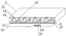
Fig. 1 is a schematic structural diagram of the present invention.
Fig. 2 is a schematic structural view of the disinfection chamber of the present invention.
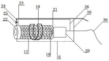
Fig. 3 is a schematic structural view of the cleaning room of the present invention.
Fig. 4 is a schematic structural view of the net-shaped drum of the present invention.
Fig. 5 is a schematic structural view of the sewage collecting bin of the present invention.
In the figure: 1-box body frame, 2-disinfection bin, 3-cleaning bin, 4-dirt collecting bin, 5-disinfectant box, 6-reticular clapboard, 7-hinge, 8-disinfection bin cover, 9-partition, 10-sterile bin A, 11-sterile bin B, 12-high ozone ultraviolet disinfection lamp, 13-disinfection switch, 14-hinge B, 15-cleaning bin cover, 16-cleaning room, 17-reticular rotary drum, 18-U-shaped bracket, 19-cleaning brush, 20-driving motor, 21-rotor, 22-round disinfection sponge, 23-disinfectant tube, 24-cleaning switch, 25-disinfectant switch, 26-lead, 27-dirt collecting drawer, 28-opening, 29-transparent observation window, 30-external power line, 31-water line, 32-disinfection timer, 33-fixing frame and 34-tweezers.
Detailed Description
The technical solutions in the embodiments of the present invention will be described clearly and completely with reference to the accompanying drawings in the embodiments of the present invention, and it is obvious that the described embodiments are only some embodiments of the present invention, not all embodiments. Based on the embodiments in the present invention, all other embodiments obtained by a person skilled in the art without creative work belong to the protection scope of the present invention.
Please refer to fig. 1, in the embodiment of the present invention, including box body frame 1, disinfection storehouse 2, cleaning bin 3, filth collection bin 4 and disinfectant box 5, characterized by that box body frame 1 is through disinfecting storehouse 2, cleaning bin 3, filth collection bin 4 and disinfectant box 5 constitution, disinfection storehouse 2 is located cleaning bin 3 top, cleaning bin 3 is connected with filth collection bin 4, cleaning bin 3 is connected through netted baffle 6 with filth collection bin 4, disinfectant box 5 is located box body frame 1 upper right side, disinfection storehouse 2 has been connected through hinge 7 and has installed disinfection cang gai 8. When in use, dirt in the cleaning bin 3 enters the dirt collecting bin 4 through the mesh partition plate 6 to be collected.
Referring to fig. 2, the sterilizing chamber 2 is divided into an aseptic chamber a10 and an aseptic chamber B11 by a partition 9, a high ozone ultraviolet sterilizing lamp 12 is respectively arranged in the aseptic chamber a10 and the aseptic chamber B11, and a sterilizing switch 13 connected with the high ozone ultraviolet sterilizing lamp 12 is arranged above the sterilizing chamber 2. When in use, the non-sterilized instruments are put into the sterile bin A10 for sterilization, and the sterilized instruments are put into the sterile bin B11 for maintaining sterility, so that the circular sterilization can be realized, and the sterilized instruments are prevented from being polluted
Referring to fig. 3, the cleaning bin 3 is provided with a cleaning bin cover 15 connected by hinges B14, and four cleaning rooms 16 are arranged in the cleaning bin 3.
Referring to fig. 4, a mesh-shaped rotating drum 17 is arranged in the cleaning room 16, the mesh-shaped rotating drum 17 is supported in the cleaning room 16 through a U-shaped bracket 18, a cleaning brush 19 is arranged in the mesh-shaped rotating drum 17, a driving motor 20 is fixedly installed at the right side of the cleaning room 16, the driving motor 20 is connected with the mesh-shaped rotating drum 17 through a rotor 21, a circular disinfection sponge 22 with a circular hole is arranged at an opening of the cleaning room 16, the circular disinfection sponge 22 and the mesh-shaped rotating drum 17 are on the same horizontal line, the circular disinfection sponge 22 is connected with a disinfection solution box 5 through a disinfection solution pipe 23, a cleaning switch 24 and a disinfection solution switch 25 are arranged on the surface of the cleaning bin 3, the cleaning switch 24 is connected with the driving motor 20 through a conducting wire 26, and the disinfection solution switch 25 controls the disinfection solution pipe 23 to be communicated with the circular disinfection sponge.
Referring to fig. 5, a dirt collection drawer 27 is disposed in the dirt collection bin 4, a liquid injection port 28 is disposed above the disinfectant box 5, a transparent observation window 29 is disposed on the surface of the disinfectant box 5, an external power line 30 is mounted on the rear side of the box body frame 1, and the external power line 30 is connected with a lead 26 and a driving motor 20. In use, the liquid in the disinfectant tank 5 is observed through the transparent observation window 29.
The surface of the transparent observation window 29 is provided with a water line 31. In use, the amount of liquid in the disinfectant tank 5 is observed through the water line 31.
The surface of the box body frame 1 is provided with a disinfection timer 32. In use, the disinfection time is recorded by the disinfection timer 32.
When the device is used, the external power line 30 is connected with a power supply, alcohol is added into the disinfectant box 5, the cleaning bin cover 15 is opened, the disinfectant switch 25 is opened, disinfectant enters the circular disinfection sponge 22 through the disinfectant pipe 23, a polluted instrument is inserted into the circular disinfection sponge 22 to rotate, the disinfectant is wiped on the surface of the polluted instrument, the instrument is inserted into the mesh-shaped rotary drum 17, the cleaning switch 24 is opened, the driving motor 20 drives the mesh-shaped rotary drum 17 to rotate, the cleaning brush 19 cleans the instrument, the cleaned dirt enters the dirt collecting drawer 27 in the dirt collecting bin 4 through the mesh-shaped partition plate 6, the cleaned instrument is taken out and placed into the sterile bin A10, the disinfection switch 13 is opened, the high-ozone ultraviolet disinfection lamp 12 works to disinfect the instrument, and the disinfected instrument is placed into the sterile bin B11 for later use.
It is obvious to a person skilled in the art that the invention is not restricted to details of the above-described exemplary embodiments, but that it can be implemented in other specific forms without departing from the spirit or essential characteristics of the invention. The present embodiments are therefore to be considered in all respects as illustrative and not restrictive, the scope of the invention being indicated by the appended claims rather than by the foregoing description, and all changes which come within the meaning and range of equivalency of the claims are therefore intended to be embraced therein. Any reference sign in a claim should not be construed as limiting the claim concerned.
Furthermore, it should be understood that although the present description refers to embodiments, not every embodiment may contain only a single embodiment, and such description is for clarity only, and those skilled in the art should integrate the description, and the embodiments may be combined as appropriate to form other embodiments understood by those skilled in the art.
Claims (4)
1. An auxiliary disinfection box for oral cavity comprises a box body frame, a disinfection bin, a cleaning bin, a dirt collecting bin and a disinfectant box, and is characterized in that the box body frame is composed of the disinfection bin, the cleaning bin, the dirt collecting bin and the disinfectant box, the disinfection bin is positioned above the cleaning bin, the cleaning bin is connected with the dirt collecting bin through a net-shaped partition plate, the disinfectant box is positioned at the upper right of the box body frame, the disinfection bin is connected with a disinfection bin cover through a hinge, the disinfection bin is divided into an aseptic bin A and an aseptic bin B through a partition, a high ozone ultraviolet disinfection lamp is respectively arranged in the aseptic bin A and the aseptic bin B, a disinfection switch connected with the high ozone ultraviolet disinfection lamp is arranged above the disinfection bin, the cleaning bin is connected with the cleaning bin cover through a hinge B, four cleaning rooms are arranged in the cleaning bin, the cleaning room is internally provided with a reticular rotary drum which is supported in the cleaning room through a U-shaped support, a cleaning brush is arranged in the reticular rotary drum, the right side of the cleaning room is fixedly provided with a driving motor which is connected with the reticular rotary drum through a rotor, the opening of the cleaning room is provided with a circular disinfection sponge with a round hole, the circular disinfection sponge and the reticular rotary drum are on the same horizontal line, the circular disinfection sponge is connected with a disinfection solution box through a disinfection solution pipe, the surface of the cleaning room is provided with a cleaning switch and a disinfection solution switch, the cleaning switch is connected with the driving motor through a conducting wire, the disinfection solution switch controls the disinfection solution pipe to be communicated with the circular disinfection sponge, the dirt collection drawer is arranged in the dirt collection room, a liquid injection port is arranged above the disinfection solution box, and the surface of the disinfection solution box is provided with a transparent observation window, an external power line is installed on the rear side of the box body frame and connected with a wire and a driving motor.
2. The auxiliary disinfecting case for oral cavity according to claim 1, wherein a water line is provided on the surface of the transparent viewing window.
3. An auxiliary disinfecting case for oral cavity as claimed in claim 1, characterized in that a disinfecting timer is arranged on the surface of the case frame.
4. The auxiliary sterilizing box for oral cavity of claim 1, wherein the sterilizing chamber cover is provided with tweezers therein via a fixing frame.
Priority Applications (1)
| Application Number | Priority Date | Filing Date | Title |
|---|---|---|---|
| CN202020605635.5U CN212416440U (en) | 2020-04-21 | 2020-04-21 | Auxiliary disinfection box for oral cavity |
Applications Claiming Priority (1)
| Application Number | Priority Date | Filing Date | Title |
|---|---|---|---|
| CN202020605635.5U CN212416440U (en) | 2020-04-21 | 2020-04-21 | Auxiliary disinfection box for oral cavity |
Publications (1)
| Publication Number | Publication Date |
|---|---|
| CN212416440U true CN212416440U (en) | 2021-01-29 |
Family
ID=74294238
Family Applications (1)
| Application Number | Title | Priority Date | Filing Date |
|---|---|---|---|
| CN202020605635.5U Active CN212416440U (en) | 2020-04-21 | 2020-04-21 | Auxiliary disinfection box for oral cavity |
Country Status (1)
| Country | Link |
|---|---|
| CN (1) | CN212416440U (en) |
-
2020
- 2020-04-21 CN CN202020605635.5U patent/CN212416440U/en active Active
Similar Documents
| Publication | Publication Date | Title |
|---|---|---|
| KR101652474B1 (en) | sterilizing and cleaning device for artificial tooth | |
| CN211188389U (en) | Novel high-efficient medical instrument is with multiple case that disinfects | |
| CN212018642U (en) | Endoscope disinfection device for otolaryngological department | |
| CN212416440U (en) | Auxiliary disinfection box for oral cavity | |
| CN211071066U (en) | Sterilizing device for medical health | |
| CN210447677U (en) | Disinfection device for surgical instruments in interventional department | |
| CN214762393U (en) | Reproductive medicine laboratory is with degassing unit | |
| CN213130978U (en) | Disinfection nursing device for general surgery department | |
| CN113509574B (en) | Operating room operation disinfection nursing equipment | |
| CN115590991A (en) | Disinfection equipment for nursing appliances | |
| CN212264032U (en) | Medical instrument cleaning and sterilizing device | |
| CN212593106U (en) | Special cleaning and sterilizing cabinet for surgical instruments | |
| CN211214543U (en) | Medical sterilizer of clinical laboratory | |
| CN210020465U (en) | Disinfection cleaner for nursing | |
| CN203647747U (en) | Toothbrush and water cup drying and disinfecting container | |
| CN213194738U (en) | Medical instrument part cleaning and sterilizing device | |
| CN212090304U (en) | Multi-functional western medicine room apparatus degassing unit | |
| CN213822658U (en) | Novel sterilizer for department of stomatology | |
| CN216168007U (en) | Ultrasonic periodontal therapeutic apparatus with disinfection function | |
| CN211434270U (en) | Nurse is with dressing tray degassing unit | |
| CN213722529U (en) | A orthodontics appearance for dentistry clinic | |
| CN215915807U (en) | Ultrasonic department probe disinfection box | |
| CN213312907U (en) | Open cranium brain trauma nursing's degassing unit | |
| CN220175646U (en) | Disinfection box | |
| CN214184172U (en) | Animal doctor uses apparatus cleaning and disinfecting equipment |
Legal Events
| Date | Code | Title | Description |
|---|---|---|---|
| GR01 | Patent grant | ||
| GR01 | Patent grant |