CN212399175U - High protection type trimming machine - Google Patents
High protection type trimming machine Download PDFInfo
- Publication number
- CN212399175U CN212399175U CN202021142364.0U CN202021142364U CN212399175U CN 212399175 U CN212399175 U CN 212399175U CN 202021142364 U CN202021142364 U CN 202021142364U CN 212399175 U CN212399175 U CN 212399175U
- Authority
- CN
- China
- Prior art keywords
- fixedly connected
- cabinet body
- servo motor
- driving box
- protection
- Prior art date
- Legal status (The legal status is an assumption and is not a legal conclusion. Google has not performed a legal analysis and makes no representation as to the accuracy of the status listed.)
- Active
Links
Images

Landscapes
- Finish Polishing, Edge Sharpening, And Grinding By Specific Grinding Devices (AREA)
Abstract
The utility model relates to a high protection type trimming machine, which comprises a protective cabinet body, wherein the bottom of the protective cabinet body is provided with a workbench, the front side of the workbench is fixedly connected with a first servo motor, the upper part of the workbench is fixedly connected with a driving box, the driving box is fixedly connected with a positioning groove through a transmission shaft, the end of the transmission shaft penetrates through the outer wall of the driving box and extends to the inside of the driving box, two sides of the positioning groove are connected with an adjusting bolt through screw threads, the end of the adjusting bolt is in butt connection with a paper tube to be trimmed, the top of the protective cabinet body is fixedly connected with a crossbeam, a transverse guide rail is fixedly connected on the crossbeam, the transverse guide rail is in sliding connection with a slide block, the slide block is fixedly connected with a hydraulic cylinder through a connecting rod, the bottom of the hydraulic cylinder is fixedly connected with, the scrap dust generated in the trimming process can be cleaned, the environment pollution caused by the scrap dust is avoided, and the working safety is improved.
Description
Technical Field
The utility model relates to a high protection type trimming machine belongs to trimming machine technical field.
Background
At present, the sizes of paper tubes on the market are various, the inner diameters of the paper tubes with different sizes are different, the traditional paper tube trimming and cutting method is used for manually cutting a cutter by workers, the cutting method is low in efficiency, large in pollution, low in safety, incapable of well guaranteeing the process and easy to cause data waste.
SUMMERY OF THE UTILITY MODEL
An object of the utility model is to provide a high protection type trimming machine, it makes the trimming emery wheel carry out horizontal displacement to rotate through setting up the first lead screw of second servo motor drive, it makes the constant head tank can carry out Y axle horizontal migration to rotate through setting up first servo motor drive second lead screw, and the constant head tank can carry out 360 rotations, be convenient for treat that the trimming paper tube carries out all-round trimming, the piece dust that the trimming produced can be cleared up and collected, avoid the polluted environment to influence that the staff is healthy, with the problem of proposing in solving above-mentioned background art.
In order to achieve the above object, the utility model provides a following technical scheme:
the utility model provides a high protection type trimming machine, includes the protection cabinet body, protection cabinet body bottom is equipped with the workstation, the first servo motor of workstation front side fixedly connected with, workstation top fixedly connected with drive case, the drive case passes through transmission shaft fixedly connected with constant head tank, the transmission shaft end runs through the drive case outer wall and extends to inside the drive case, the constant head tank both sides have adjusting bolt through screw threaded connection, adjusting bolt end is contradicted and is connected and remain the trimming paper pipe, protection cabinet body top fixedly connected with crossbeam, fixedly connected with horizontal guide rail on the crossbeam, horizontal guide rail sliding connection has the slider, the slider passes through connecting rod fixedly connected with hydraulic cylinder, hydraulic cylinder bottom fixedly connected with trimming emery wheel.
Furthermore, a second servo motor is fixedly connected to one side of the protection cabinet body, a first lead screw is fixedly connected to the output end of the second servo motor, a first threaded sleeve is in threaded connection with the first lead screw, and the bottom of the first threaded sleeve is fixedly connected with the hydraulic oil cylinder.
Further, the bottom of the protection cabinet body is fixedly connected with a base, the dust collecting box is fixedly connected with the top of the base, a filter screen is arranged inside the dust collecting box, the air extractor is fixedly connected with the top of the dust collecting box, and the tail end of the air extractor penetrates through the outer wall of the protection cabinet body and extends to the inside of the protection cabinet body.
Furthermore, the workstation both sides are equipped with leads the bits board, it is inside that lead the bits board end to be located the base, it is equipped with the piece collecting box to lead the bits board below, piece collecting box and base inner wall sliding connection, protective cabinet body both sides are rotated through the hinge and are connected with the guard gate, be equipped with the observation frame on the guard gate, the observation frame is the glass steel material.
Furthermore, a second screw rod is arranged inside the workbench and fixedly connected with the output end of the first servo motor, a second screw rod is in threaded connection with a second threaded sleeve, and the upper surface of the second threaded sleeve is fixedly connected with the driving box.
Furthermore, a third servo motor is arranged inside the driving box, the output end of the third servo motor is fixedly connected with a first bevel gear, the first bevel gear is connected with a second bevel gear in a meshed mode, and the gear center of the second bevel gear is fixedly connected with the transmission shaft.
The utility model has the advantages that:
1. the second servo motor is arranged to drive the first screw rod to rotate, so that the trimming grinding wheel can horizontally move in an X axis, the hydraulic oil cylinder can control the trimming grinding wheel to perform lifting motion, so that the cutting or polishing distance is controlled, the first servo motor is arranged to drive the second screw rod to rotate, so that the positioning groove can horizontally move in a Y axis, the positioning groove is matched with the driving box to perform omnibearing trimming on a paper tube to be trimmed, the processing precision is improved, manual operation of workers is not needed, and the safety protection performance is improved;
2. the dust in the protective cabinet body can be collected by arranging the air pump, the collected dust falls into the dust collecting box, the collected dust can be prevented from flowing back by arranging the filter screen, the dust can be collected, the phenomenon that the environment is polluted by more dust generated in the trimming process and the influence on health is caused by the fact that workers suck the dust can be avoided;
3. can unify the collection to the piece that the in-process produced of repairing and cutting through setting up chip guide plate and piece collecting box, the piece of collecting is carried out periodic cleaning by the staff, can avoid iron fillings to splash to the safety of staff and cause harm in the course of working through setting up the guard gate, and the observation frame on the guard gate is the glass steel material, and the staff of being convenient for looks over the processing condition of the internal portion of guard cabinet, has safeguard function simultaneously, can guarantee staff's safety.
Drawings
The accompanying drawings are included to provide a further understanding of the invention, and are incorporated in and constitute a part of this specification, illustrate embodiments of the invention, and together with the description serve to explain the invention and not to limit the invention.
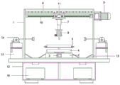
FIG. 1 is a schematic view of the overall structure of a high-protection trimming machine of the present invention;
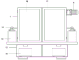
FIG. 2 is a front view of the high-protection trimming machine of the present invention;
FIG. 3 is a schematic view of the internal structure of the workbench of the high-protection trimming machine of the present invention;
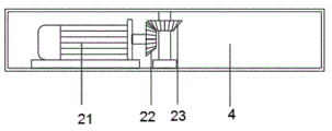
FIG. 4 is a schematic view of the internal structure of the driving box of the high-protection trimming machine of the present invention;
reference numbers in the figures: 1. a protective cabinet body; 2. a work table; 3. a first servo motor; 4. a drive box; 5. positioning a groove; 6. a transverse guide rail; 7. a hydraulic cylinder; 8. trimming a grinding wheel; 9. a second servo motor; 10. a first lead screw; 11. a first threaded sleeve; 12. a base; 13. a dust collection box; 14. an air extractor; 15. a scrap guide plate; 16. a debris collection bin; 17. a protective door; 18. an observation frame; 19. a second lead screw; 20. a second threaded sleeve; 21. a third servo motor; 22. a first bevel gear; 23. a second bevel gear.
Detailed Description
The technical solutions in the embodiments of the present invention will be described clearly and completely with reference to the accompanying drawings in the embodiments of the present invention, and it is obvious that the described embodiments are only some embodiments of the present invention, not all embodiments. Based on the embodiments in the present invention, all other embodiments obtained by a person skilled in the art without creative work belong to the protection scope of the present invention.
Referring to fig. 1-4, the present invention provides a technical solution:
the utility model provides a high protection type trimming machine, includes the protection cabinet body 1, 1 bottom of the protection cabinet body is equipped with workstation 2, 2 front side fixedly connected with servo motor 3 of workstation, 2 top fixedly connected with drive case 4 of workstation, drive case 4 passes through transmission shaft fixedly connected with constant head tank 5, the transmission shaft end runs through 4 outer walls of drive case and extends to inside 4 drive cases, there is adjusting bolt constant head tank 5 both sides through screw threaded connection, adjusting bolt end is contradicted and is connected and remain to trim the paper tube, 1 top fixedly connected with crossbeam of the protection cabinet body, fixedly connected with horizontal guide rail 6 on the crossbeam, 6 sliding connection of horizontal guide rail has the slider, the slider passes through connecting rod fixedly connected with hydraulic cylinder 7, 7 bottom fixedly connected with of hydraulic cylinder repaiies and cuts emery wheel 8.
Specifically, as shown in fig. 1, one side of the protection cabinet body 1 is fixedly connected with a second servo motor 9, an output end of the second servo motor 9 is fixedly connected with a first screw rod 10, the first screw rod 10 is in threaded connection with a first threaded sleeve 11, the bottom of the first threaded sleeve 11 is fixedly connected with a hydraulic oil cylinder 7, the second servo motor 9 is arranged to drive the first screw rod 10 to rotate, so that the trimming grinding wheel 8 can perform X-axis horizontal movement, and the hydraulic oil cylinder 7 can control the trimming grinding wheel 8 to perform lifting movement, thereby controlling the cutting or polishing distance.
Specifically, as shown in fig. 1-2, a base 12 is fixedly connected to the bottom of the protection cabinet 1, a dust collection box 13 is fixedly connected to the top of the base 12, a filter screen is arranged inside the dust collection box 13, an air extractor 14 is fixedly connected to the top of the dust collection box 13, the end of the air extractor 14 penetrates through the outer wall of the protection cabinet 1 and extends to the inside of the protection cabinet 1, the dust inside the protection cabinet 1 can be collected by arranging the air extractor 14, the collected dust falls into the dust collection box 13, the collected dust can be prevented from flowing back by arranging the filter screen, the dust can be collected to avoid generating more dust pollution to the environment during trimming, the dust sucked by a worker can affect the health, chip guide plates 15 are arranged on both sides of the workbench 2, the end of the chip guide plate 15 is positioned inside the base 12, and a chip collection box 16 is arranged below the chip guide plate, the utility model discloses a safe and clean protective cabinet, including protective cabinet body 1, chip collecting box 16 and base 12 inner wall sliding connection, protective cabinet body 1 both sides are connected with guard gate 17 through the hinge rotation, be equipped with observation frame 18 on the guard gate 17, observation frame 18 is the glass steel material, can unify the collection to the piece that the trimming in-process produced through setting up scrap guide 15 and chip collecting box 16, and the piece of collection is regularly cleared up by the staff, can avoid iron fillings to splash to cause harm to staff's safety in the course of working through setting up guard gate 17, and observation frame 18 on the guard gate 17 is the glass steel material, and the staff of being convenient for looks over the processing condition of protective cabinet body 1 inside, has safeguard function simultaneously, can guarantee staff's safety.
Specifically, as shown in fig. 3, the inside second lead screw 19 that is equipped with of workstation 2, second lead screw 19 and the fixed connection of 3 output ends of first servo motor, 19 threaded connection of second lead screw has second thread bush 20, 20 upper surfaces of second thread bush and drive case 4 fixed connection rotate through setting up first servo motor 3 and make constant head tank 5 can carry out Y axle horizontal migration, use with drive case 4 cooperation and can treat the trim paper tube and carry out all-round trim, and the machining precision promotes to some extent, does not need staff's manual operation, and safety protection nature improves.
Specifically, as shown in fig. 4, a third servo motor 21 is arranged inside the driving box 4, an output end of the third servo motor 21 is fixedly connected with a first bevel gear 22, the first bevel gear 22 is engaged with a second bevel gear 23, and an axis of the second bevel gear 23 is fixedly connected with the transmission shaft.
The utility model discloses the theory of operation: the utility model discloses at first will wait to repair and cut the paper tube and place inside constant head tank 5 when using. The second servo motor 9 is arranged to drive the first screw rod 10 to rotate so that the trimming grinding wheel 8 can horizontally move along the X axis, the hydraulic oil cylinder 7 can control the trimming grinding wheel 8 to carry out lifting motion so as to control the cutting or polishing distance, the first servo motor 3 is arranged to drive the second screw rod 19 to rotate so that the positioning groove 5 can horizontally move along the Y axis, the trimming grinding wheel is matched with the driving box 4 to carry out omnibearing trimming on a paper tube to be trimmed, the processing precision is improved, manual operation of workers is not needed, the safety protection is improved, dust in the protection cabinet body 1 can be collected by the air pump 14, the collected dust falls into the dust collection box 13, the collected dust can be prevented from flowing back by the filter screen, the dust can be collected so that the environment polluted by more dust generated in the trimming process, and the influence on health can be caused by the workers who suck the dust, can unify the collection to the piece that the trimming in-process produced through setting up chip guide plate 15 and piece collecting box 16, the piece of collection is regularly cleared up by the staff, can avoid iron fillings to splash and cause harm to staff's safety in the course of working through setting up guard gate 17, and the observation frame 18 on the guard gate 17 is the glass steel material, and the staff of being convenient for looks over the processing condition of the protection cabinet body 1 inside, has safeguard function simultaneously, can guarantee staff's safety.
It is obvious to a person skilled in the art that the invention is not restricted to details of the above-described exemplary embodiments, but that it can be implemented in other specific forms without departing from the spirit or essential characteristics of the invention. The present embodiments are therefore to be considered in all respects as illustrative and not restrictive, the scope of the invention being indicated by the appended claims rather than by the foregoing description, and all changes which come within the meaning and range of equivalency of the claims are therefore intended to be embraced therein. Any reference sign in a claim should not be construed as limiting the claim concerned.
Furthermore, it should be understood that although the present description refers to embodiments, not every embodiment may contain only a single embodiment, and such description is for clarity only, and those skilled in the art should integrate the description, and the embodiments may be combined as appropriate to form other embodiments understood by those skilled in the art.
Claims (6)
1. The utility model provides a high protection type trimming machine, includes the protection cabinet body (1), its characterized in that: a workbench (2) is arranged at the bottom of the protection cabinet body (1), a first servo motor (3) is fixedly connected with the front side of the workbench (2), a driving box (4) is fixedly connected above the workbench (2), the driving box (4) is fixedly connected with a positioning groove (5) through a transmission shaft, the tail end of the transmission shaft penetrates through the outer wall of the driving box (4) and extends into the driving box (4), two sides of the positioning groove (5) are connected with an adjusting bolt through screw threads, the tail end of the adjusting bolt is in butt joint with a paper tube to be trimmed, the top of the protection cabinet body (1) is fixedly connected with a crossbeam, a transverse guide rail (6) is fixedly connected on the crossbeam, the transverse guide rail (6) is connected with a slide block in a sliding way, the slide block is fixedly connected with a hydraulic oil cylinder (7) through a connecting rod, the bottom of the hydraulic oil cylinder (7) is fixedly connected with a trimming grinding wheel (8).
2. The high-protection type trimming machine according to claim 1, wherein: the protection cabinet is characterized in that a second servo motor (9) is fixedly connected to one side of the protection cabinet body (1), a first lead screw (10) is fixedly connected to the output end of the second servo motor (9), a first thread bush (11) is in threaded connection with the first lead screw (10), and the bottom of the first thread bush (11) is fixedly connected with a hydraulic oil cylinder (7).
3. The high-protection type trimming machine according to claim 1, wherein: the protection cabinet body (1) bottom fixedly connected with base (12), base (12) top fixedly connected with dust collecting box (13), the inside filter screen that is equipped with of dust collecting box (13), dust collecting box (13) top fixedly connected with air extractor (14), air extractor (14) end runs through protection cabinet body (1) outer wall and extends to inside the protection cabinet body (1).
4. The high-protection type trimming machine according to claim 1, wherein: workstation (2) both sides are equipped with and lead bits board (15), it is inside that lead bits board (15) end is located base (12), it is equipped with piece collecting box (16) to lead bits board (15) below, piece collecting box (16) and base (12) inner wall sliding connection, protective cabinet body (1) both sides are connected with guard gate (17) through the hinge rotation, be equipped with on guard gate (17) and observe frame (18), observe frame (18) are the glass steel material.
5. The high-protection type trimming machine according to claim 1, wherein: the novel hydraulic servo motor is characterized in that a second lead screw (19) is arranged inside the workbench (2), the second lead screw (19) is fixedly connected with the output end of the first servo motor (3), a second thread sleeve (20) is connected to the second lead screw (19) in a threaded mode, and the upper surface of the second thread sleeve (20) is fixedly connected with the driving box (4).
6. The high-protection type trimming machine according to claim 1, wherein: the driving box (4) is internally provided with a third servo motor (21), the output end of the third servo motor (21) is fixedly connected with a first bevel gear (22), the first bevel gear (22) is meshed with a second bevel gear (23), and the axis of the second bevel gear (23) is fixedly connected with a transmission shaft.
Priority Applications (1)
| Application Number | Priority Date | Filing Date | Title |
|---|---|---|---|
| CN202021142364.0U CN212399175U (en) | 2020-06-19 | 2020-06-19 | High protection type trimming machine |
Applications Claiming Priority (1)
| Application Number | Priority Date | Filing Date | Title |
|---|---|---|---|
| CN202021142364.0U CN212399175U (en) | 2020-06-19 | 2020-06-19 | High protection type trimming machine |
Publications (1)
| Publication Number | Publication Date |
|---|---|
| CN212399175U true CN212399175U (en) | 2021-01-26 |
Family
ID=74407598
Family Applications (1)
| Application Number | Title | Priority Date | Filing Date |
|---|---|---|---|
| CN202021142364.0U Active CN212399175U (en) | 2020-06-19 | 2020-06-19 | High protection type trimming machine |
Country Status (1)
| Country | Link |
|---|---|
| CN (1) | CN212399175U (en) |
Cited By (2)
| Publication number | Priority date | Publication date | Assignee | Title |
|---|---|---|---|---|
| CN113290491A (en) * | 2021-06-16 | 2021-08-24 | 杭州德凯利医疗器材有限公司 | False tooth processing multi-angle polishing machine capable of synchronously removing dust |
| CN114043230A (en) * | 2021-11-05 | 2022-02-15 | 广州华商学院 | Rapid forming device for intelligent processing of industrial design metal and use method |
-
2020
- 2020-06-19 CN CN202021142364.0U patent/CN212399175U/en active Active
Cited By (2)
| Publication number | Priority date | Publication date | Assignee | Title |
|---|---|---|---|---|
| CN113290491A (en) * | 2021-06-16 | 2021-08-24 | 杭州德凯利医疗器材有限公司 | False tooth processing multi-angle polishing machine capable of synchronously removing dust |
| CN114043230A (en) * | 2021-11-05 | 2022-02-15 | 广州华商学院 | Rapid forming device for intelligent processing of industrial design metal and use method |
Similar Documents
| Publication | Publication Date | Title |
|---|---|---|
| CN212399175U (en) | High protection type trimming machine | |
| CN108723794A (en) | A kind of cutting base and its application method of stock-removing machine | |
| CN211589210U (en) | Numerical control drilling and milling machine for machining | |
| CN215746788U (en) | Numerical control sawing machine for machining | |
| CN211219872U (en) | Dust collector is used in milling machine processing | |
| CN216461763U (en) | Novel numerical control lathe | |
| CN216680508U (en) | Broach horizontal broaching machine convenient to clearance piece | |
| CN215659729U (en) | Electromechanical integrated numerical control machining equipment with scrap collecting function | |
| CN214236433U (en) | Milling machine with cleaning function | |
| CN210147633U (en) | Milling machine with cleaning device | |
| CN210909056U (en) | Universal horizontal lifting table milling machine | |
| CN211940044U (en) | Milling machine with dust collection function | |
| CN113997187A (en) | Lathe that possesses garbage collection function | |
| CN208099936U (en) | A kind of milling machine table clearing apparatus | |
| CN112247284A (en) | Gear shaping device for gear machining of new energy automobile and use method of gear shaping device | |
| CN217493364U (en) | Numerical control drilling, tapping and milling integrated machine | |
| CN217991845U (en) | Milling machine for metalworking with safeguard function | |
| CN212311760U (en) | Machine tool cross beam grinding machine | |
| CN110756899A (en) | Numerical control band saw machine convenient to adjust saw blade rate of tension | |
| CN220427711U (en) | Milling machine | |
| CN220463115U (en) | Horizontal machining center capable of continuously machining | |
| CN219648795U (en) | Milling machine convenient for cleaning waste residues | |
| CN220427017U (en) | Steel construction panel cutting machine | |
| CN212526279U (en) | A unable adjustment base for broaching cutter | |
| CN220592245U (en) | Improved milling machine workbench |
Legal Events
| Date | Code | Title | Description |
|---|---|---|---|
| GR01 | Patent grant | ||
| GR01 | Patent grant |