CN212398873U - Clamping tool for machining inner gear of robot accessory - Google Patents
Clamping tool for machining inner gear of robot accessory Download PDFInfo
- Publication number
- CN212398873U CN212398873U CN202021045290.9U CN202021045290U CN212398873U CN 212398873 U CN212398873 U CN 212398873U CN 202021045290 U CN202021045290 U CN 202021045290U CN 212398873 U CN212398873 U CN 212398873U
- Authority
- CN
- China
- Prior art keywords
- threaded rod
- fixedly connected
- splint
- rod
- machining
- Prior art date
- Legal status (The legal status is an assumption and is not a legal conclusion. Google has not performed a legal analysis and makes no representation as to the accuracy of the status listed.)
- Expired - Fee Related
Links
Images


Landscapes
- Gripping Jigs, Holding Jigs, And Positioning Jigs (AREA)
Abstract
The utility model discloses a centre gripping frock is used in gear machining of robot fitting, including workstation, spout, support frame and splint, the bottom fixedly connected with pillar of workstation, the inside of workstation is provided with adjusts the structure, the top of spout is provided with the support frame, and the inside of support frame is provided with flip structure, the fixed slot sets up in the inside of support frame, one side fixedly connected with splint of flip structure, and one side of splint are provided with the centre gripping groove, the inside of splint is provided with limit structure. The utility model discloses a be provided with fixed slot, axis of rotation, gear train, connecting rod and rocker, axis of rotation and connecting rod set up in the both sides of gear train, are the meshing between the pinion rack of gear train and connect, and be welding integrated structure between connecting rod and the rocker, through rotating the rocker, can indirectly drive the axis of rotation and rotate, realized the rotation to the material to make the device have the upset function.
Description
Technical Field
The utility model relates to an internal gear machining technical field specifically is a centre gripping frock is used in robot fitting internal gear machining.
Background
Along with the high-speed development of society, the technological level constantly improves, and robot equipment has merged into people's life, in the assembly line of mill, often is provided with the robot of automation mechanized operation, and the internal gear is the important part of the inside power transmission of robot, but there are many problems or defects in the centre gripping frock for gear machining in the current robot accessory:
in actual use, when a machined material is turned over, the traditional clamping tool for machining the inner gear of the robot accessory needs to be taken down from the device and then fixed again, so that the device is inconvenient to turn over.
SUMMERY OF THE UTILITY MODEL
An object of the utility model is to provide a centre gripping frock is used in gear machining in robot fitting to the problem of the upset of not being convenient for of the device is proposed in solving above-mentioned background art.
In order to achieve the above object, the utility model provides a following technical scheme: a clamping tool for machining an inner gear of a robot accessory comprises a workbench, a sliding chute, a supporting frame and a clamping plate, the bottom end of the workbench is fixedly connected with a table post, the interior of the workbench is provided with an adjusting structure, the bottom end of the workbench is provided with a chute, the top end of the chute is provided with a support frame, and the inside of the supporting frame is provided with a turnover structure which comprises a fixed groove, a rotating shaft, a gear set, a connecting rod and a rocker, the fixing groove is arranged inside the support frame, a gear set is arranged inside the fixing groove, one side of the gear set is fixedly connected with a rotating shaft, the other side of the gear set is fixedly connected with a connecting rod, and one side fixedly connected with rocker of connecting rod, one side fixedly connected with splint of flip structure, and one side of splint is provided with the centre gripping groove, the inside of splint is provided with limit structure.
Preferably, adjust the structure and include cavity, threaded rod, fixed block, slider and regulating wheel, the cavity sets up in the inside of workstation, the inside of cavity is provided with the threaded rod, and one side swing joint of threaded rod has the fixed block, swing joint has the slider on the lateral wall of threaded rod, the opposite side fixedly connected with regulating wheel of threaded rod.
Preferably, the threaded rod runs through in the inside of workstation, one side fixed connection of fixed block is on the inside wall of workstation, the screw thread on the threaded rod lateral wall is well symmetric distribution, the slider is symmetric distribution on the threaded rod.
Preferably, a welding integrated structure is formed between the rotating shaft and the gear set, the rotating shaft penetrates through one side of the supporting frame, the connecting rod penetrates through the other side of the supporting frame, and the connecting rod and the rocker are in the welding integrated structure.
Preferably, limit structure includes movable groove, tensile pole, spring and limiting plate, the movable groove sets up in the inside of splint, the inside swing joint in movable groove has tensile pole, and swing joint has the spring on the lateral wall of tensile pole, the top fixedly connected with limiting plate of tensile pole.
Preferably, the activity groove is the symmetric distribution on splint, the spring housing is established in the outside of tensile pole, the spring is inlayed in the inside of activity groove, be welding integrated structure between tensile pole and the limiting plate.
Compared with the prior art, the beneficial effects of the utility model are that: the clamping tool for machining the gear in the robot accessory not only realizes the overturning function, but also realizes the functions of conveniently adjusting and limiting the clamping distance;
(1) the material turning device is provided with the fixing grooves, the turning shaft, the gear set, the connecting rod and the rocker, wherein the turning shaft and the connecting rod are arranged on two sides of the gear set, toothed plates of the gear set are in meshed connection, the connecting rod and the rocker are in a welding integrated structure, and the turning shaft can be indirectly driven to turn by turning the rocker, so that the material turning device has a turning function;
(2) the cavity, the threaded rod, the fixed block, the sliding blocks and the adjusting wheel are arranged, the threaded rod is arranged in the workbench and penetrates through one side of the workbench to rotate with the adjusting wheel, threads on the outer side wall of the threaded rod are arranged in a centrosymmetric mode, the distance between the sliding blocks can be adjusted through rotation of the adjusting wheel, and the size of the clamping distance of the device is adjusted, so that the device is convenient to adjust;
(3) through being provided with movable groove, tensile pole, spring and limiting plate, the movable groove is the symmetric distribution in the inside of splint, has improved the tensile stability that the limiting plate makes progress, and the outside cover of tensile pole is equipped with the spring, and the elasticity of usable spring carries out the centre gripping to processing material spacing to make the device have prevent skew and spacing function.
Drawings
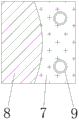
Fig. 1 is a schematic front view of the present invention;
fig. 2 is a schematic view of the front cross-sectional structure of the adjusting structure of the present invention;
fig. 3 is a schematic view of the front cross-sectional structure of the turnover structure of the present invention;
fig. 4 is a schematic view of the front view cross section structure of the limiting structure of the present invention;
fig. 5 is a schematic view of the top-view cross-sectional structure of the limiting structure of the present invention.
In the figure: 1. a work table; 2. a pillar; 3. an adjustment structure; 301. a chamber; 302. a threaded rod; 303. a fixed block; 304. a slider; 305. an adjustment wheel; 4. a chute; 5. a turning structure; 501. fixing grooves; 502. a rotating shaft; 503. a gear set; 504. a connecting rod; 505. a rocker; 6. a support frame; 7. a splint; 8. a clamping groove; 9. a limiting structure; 901. a movable groove; 902. a stretch rod; 903. a spring; 904. and a limiting plate.
Detailed Description
The technical solutions in the embodiments of the present invention will be described clearly and completely with reference to the accompanying drawings in the embodiments of the present invention, and it is obvious that the described embodiments are only some embodiments of the present invention, not all embodiments. Based on the embodiments in the present invention, all other embodiments obtained by a person skilled in the art without creative work belong to the protection scope of the present invention.
Referring to fig. 1-5, the present invention provides an embodiment: the utility model provides a centre gripping frock is used in processing of robot accessory internal gear, comprises a workbench 1, spout 4, support frame 6 and splint 7, the bottom fixedly connected with post 2 of workstation 1, the inside of workstation 1 is provided with adjusts structure 3, adjust structure 3 includes cavity 301, threaded rod 302, fixed block 303, slider 304 and regulating wheel 305, cavity 301 sets up in the inside of workstation 1, the inside of cavity 301 is provided with threaded rod 302, and one side swing joint of threaded rod 302 has fixed block 303, swing joint has slider 304 on the lateral wall of threaded rod 302, the opposite side fixedly connected with regulating wheel 305 of threaded rod 302, threaded rod 302 runs through the inside of workstation 1, one side fixed connection of fixed block 303 is on the inside wall of workstation 1, the screw on the lateral wall of threaded rod 302 is well symmetric distribution, slider 304 is symmetric distribution on threaded rod 302;
when the device is used, the cavity 301, the threaded rod 302, the fixed block 303, the sliding block 304 and the adjusting wheel 305 are arranged, the threaded rod 302 is arranged inside the workbench 1 and penetrates through one side of the workbench 1 to rotate with the adjusting wheel 305, threads on the outer side wall of the threaded rod 302 are arranged in a centrosymmetric manner, the adjusting wheel 305 rotates, the distance between the sliding blocks 304 can be adjusted, the size of the clamping distance of the device is adjusted, and therefore the device is convenient to adjust;
the bottom end of the workbench 1 is provided with a sliding chute 4, the top end of the sliding chute 4 is provided with a support frame 6, the inside of the support frame 6 is provided with a turnover structure 5, the turnover structure 5 comprises a fixing groove 501, a rotating shaft 502, a gear set 503, a connecting rod 504 and a rocker 505, the fixing groove 501 is arranged inside the support frame 6, the inside of the fixing groove 501 is provided with the gear set 503, one side of the gear set 503 is fixedly connected with the rotating shaft 502, the other side of the gear set 503 is fixedly connected with the connecting rod 504, one side of the connecting rod 504 is fixedly connected with the rocker 505, the rotating shaft 502 and the gear set 503 are in a welding integrated structure, the rotating shaft 502 penetrates through one side of the support frame 6, the connecting;
when the device is used, the fixing groove 501, the rotating shaft 502, the gear set 503, the connecting rod 504 and the rocker 505 are arranged, the rotating shaft 502 and the connecting rod 504 are arranged on two sides of the gear set 503, toothed plates of the gear set 503 are connected in a meshed mode, the connecting rod 504 and the rocker 505 are in a welding integrated structure, the rotating shaft 502 can be indirectly driven to rotate by rotating the rocker 505, rotation of materials is achieved, and therefore the device has a turnover function;
one side of the turnover structure 5 is fixedly connected with a clamping plate 7, one side of the clamping plate 7 is provided with a clamping groove 8, a limiting structure 9 is arranged inside the clamping plate 7, the limiting structure 9 comprises a movable groove 901, a stretching rod 902, a spring 903 and a limiting plate 904, the movable groove 901 is arranged inside the clamping plate 7, the interior of the movable groove 901 is movably connected with the stretching rod 902, the outer side wall of the stretching rod 902 is movably connected with the spring 903, the top end of the stretching rod 902 is fixedly connected with the limiting plate 904, the movable grooves 901 are symmetrically distributed on the clamping plate 7, the spring 903 is sleeved outside the stretching rod 902, the spring 903 is embedded inside the movable groove 901, and the stretching rod 902 and the limiting plate 904 are of a welding integrated structure;
during the use, through being provided with activity groove 901, tensile pole 902, spring 903 and limiting plate 904, activity groove 901 is the symmetric distribution in splint 7's inside, has improved the tensile stability that limiting plate 904 made progress, and the outside cover of tensile pole 902 is equipped with spring 903, and the elasticity of usable spring 903 carries out the centre gripping spacingly to processing material to it has skew and spacing function to make the device prevent.
The working principle is as follows: when the device is used, firstly, the device is taken out and transported to a target area, the clamping distance of the device is adjusted according to the size of a material to be processed, the adjusting wheel 305 is firstly held and rotated to drive the threaded rod 302 to rotate, and the supporting frame 6 is indirectly driven to change the distance;
secondly, limiting and fixing the processing material, adjusting the size of the clamping groove 8 according to the height of the processing material, grabbing the limiting plate 904 and dragging upwards, placing the processing material into the clamping groove 8 when the distance between the clamping grooves 8 is larger than the height of the processing material, and then loosening the limiting plate 904;
finally, in the process of processing the processing material, when the processing material needs to be turned over, the rocker 505 is held and rotated, and the rocker 505 can indirectly drive the rotating shaft 502 to rotate, so that the clamping plate 7 is driven to turn over, and the device is finally used.
It is obvious to a person skilled in the art that the invention is not restricted to details of the above-described exemplary embodiments, but that it can be implemented in other specific forms without departing from the spirit or essential characteristics of the invention. The present embodiments are therefore to be considered in all respects as illustrative and not restrictive, the scope of the invention being indicated by the appended claims rather than by the foregoing description, and all changes which come within the meaning and range of equivalency of the claims are therefore intended to be embraced therein. Any reference sign in a claim should not be construed as limiting the claim concerned.
Claims (6)
1. The utility model provides a centre gripping frock is used in machining of robot fitting internal gear, includes workstation (1), spout (4), support frame (6) and splint (7), its characterized in that: the bottom end of the workbench (1) is fixedly connected with a table column (2), the inside of the workbench (1) is provided with an adjusting structure (3), the bottom end of the workbench (1) is provided with a sliding groove (4), the top end of the sliding groove (4) is provided with a supporting frame (6), the inside of the supporting frame (6) is provided with a turnover structure (5), the turnover structure (5) comprises a fixing groove (501), a rotating shaft (502), a gear set (503), a connecting rod (504) and a rocker (505), the fixing groove (501) is arranged inside the supporting frame (6), the inside of the fixing groove (501) is provided with the gear set (503), one side of the gear set (503) is fixedly connected with the rotating shaft (502), the other side of the gear set (503) is fixedly connected with the connecting rod (504), and one side of the connecting rod (504), one side fixedly connected with splint (7) of flip structure (5), and one side of splint (7) is provided with centre gripping groove (8), the inside of splint (7) is provided with limit structure (9).
2. The clamping tool for machining the inner gear of the robot accessory in the claim 1 is characterized in that: adjust structure (3) and include cavity (301), threaded rod (302), fixed block (303), slider (304) and regulating wheel (305), cavity (301) sets up in the inside of workstation (1), the inside of cavity (301) is provided with threaded rod (302), and one side swing joint of threaded rod (302) has fixed block (303), swing joint has slider (304) on the lateral wall of threaded rod (302), the opposite side fixedly connected with regulating wheel (305) of threaded rod (302).
3. The clamping tool for machining the inner gear of the robot accessory as claimed in claim 2, wherein the clamping tool comprises: threaded rod (302) run through in the inside of workstation (1), one side fixed connection of fixed block (303) is on the inside wall of workstation (1), symmetric distribution in the screw thread on threaded rod (302) lateral wall is, slider (304) are symmetric distribution on threaded rod (302).
4. The clamping tool for machining the inner gear of the robot accessory in the claim 1 is characterized in that: the rotating shaft (502) and the gear set (503) are in a welding integrated structure, the rotating shaft (502) penetrates through one side of the supporting frame (6), the connecting rod (504) penetrates through the other side of the supporting frame (6), and the connecting rod (504) and the rocker (505) are in a welding integrated structure.
5. The clamping tool for machining the inner gear of the robot accessory in the claim 1 is characterized in that: the limiting structure (9) comprises a movable groove (901), a stretching rod (902), a spring (903) and a limiting plate (904), the movable groove (901) is arranged inside the clamping plate (7), the stretching rod (902) is movably connected inside the movable groove (901), the spring (903) is movably connected to the outer side wall of the stretching rod (902), and the limiting plate (904) is fixedly connected to the top end of the stretching rod (902).
6. The clamping tool for machining the inner gear of the robot accessory in the claim 5 is characterized in that: the movable grooves (901) are symmetrically distributed on the clamping plate (7), the spring (903) is sleeved on the outer side of the stretching rod (902), the spring (903) is embedded in the movable grooves (901), and the stretching rod (902) and the limiting plate (904) are in a welding integrated structure.
Priority Applications (1)
| Application Number | Priority Date | Filing Date | Title |
|---|---|---|---|
| CN202021045290.9U CN212398873U (en) | 2020-06-09 | 2020-06-09 | Clamping tool for machining inner gear of robot accessory |
Applications Claiming Priority (1)
| Application Number | Priority Date | Filing Date | Title |
|---|---|---|---|
| CN202021045290.9U CN212398873U (en) | 2020-06-09 | 2020-06-09 | Clamping tool for machining inner gear of robot accessory |
Publications (1)
| Publication Number | Publication Date |
|---|---|
| CN212398873U true CN212398873U (en) | 2021-01-26 |
Family
ID=74408976
Family Applications (1)
| Application Number | Title | Priority Date | Filing Date |
|---|---|---|---|
| CN202021045290.9U Expired - Fee Related CN212398873U (en) | 2020-06-09 | 2020-06-09 | Clamping tool for machining inner gear of robot accessory |
Country Status (1)
| Country | Link |
|---|---|
| CN (1) | CN212398873U (en) |
-
2020
- 2020-06-09 CN CN202021045290.9U patent/CN212398873U/en not_active Expired - Fee Related
Similar Documents
| Publication | Publication Date | Title |
|---|---|---|
| CN213164165U (en) | Gantry machining center with high production efficiency | |
| CN212398873U (en) | Clamping tool for machining inner gear of robot accessory | |
| CN112170930B (en) | Vertical cutting device is used in road and bridge construction | |
| CN206899073U (en) | A kind of telescopic jig of field of machining | |
| CN211540844U (en) | Clamping device for surface grinding machine | |
| CN210731683U (en) | Numerical control lathe major axis processing mounting fixture | |
| CN210334651U (en) | Angle adjusting device for wire cutting machine | |
| CN211360936U (en) | Adjustable high-precision tapping machine | |
| CN207787469U (en) | A kind of press machine | |
| CN212398863U (en) | Anchor clamps for machining convenient to adjust | |
| CN216126658U (en) | Spark machine for punching die | |
| CN215035533U (en) | Mechanical equipment internal stay anchor clamps | |
| CN211466103U (en) | Jig for manufacturing novel heat pipe | |
| CN212762881U (en) | Positioning fixture is used in processing of nodular cast iron work piece | |
| CN210648790U (en) | Automobile engine die casting stub bar saw cuts frock | |
| CN219787438U (en) | Ultra-precise numerical control machining clamp | |
| CN207309001U (en) | A kind of radial drilling machine | |
| CN202622090U (en) | Cyclone mill with rear-mounted motor | |
| CN214870033U (en) | Adjustable metal jig clamping device | |
| CN215917277U (en) | Novel homogeneity goods shelves with regulatory function | |
| CN214185256U (en) | Device with quick feeding structure based on machine tool | |
| CN220216847U (en) | Grooving equipment for steel structure machining | |
| CN218694621U (en) | Tapping machine with movable tapping mechanism | |
| CN218840937U (en) | Feeding device for machining machine bed plates | |
| CN214264036U (en) | Diamond wire drawing mould processing is with milling device |
Legal Events
| Date | Code | Title | Description |
|---|---|---|---|
| GR01 | Patent grant | ||
| GR01 | Patent grant | ||
| CF01 | Termination of patent right due to non-payment of annual fee | ||
| CF01 | Termination of patent right due to non-payment of annual fee |
Granted publication date: 20210126 |