CN212397091U - Hydraulic cylinder subassembly application production facility - Google Patents
Hydraulic cylinder subassembly application production facility Download PDFInfo
- Publication number
- CN212397091U CN212397091U CN202020722035.7U CN202020722035U CN212397091U CN 212397091 U CN212397091 U CN 212397091U CN 202020722035 U CN202020722035 U CN 202020722035U CN 212397091 U CN212397091 U CN 212397091U
- Authority
- CN
- China
- Prior art keywords
- fixedly connected
- hydraulic cylinder
- shell
- motor
- top surface
- Prior art date
- Legal status (The legal status is an assumption and is not a legal conclusion. Google has not performed a legal analysis and makes no representation as to the accuracy of the status listed.)
- Active
Links
Images


Abstract
The utility model provides a hydraulic cylinder subassembly application production facility relates to application equipment technical field. This pneumatic cylinder subassembly application production facility, which comprises a housin, the board is placed to the inside fixedly connected with of casing, the inside wall fixedly connected with spraying device of casing, the one end fixedly connected with feeding device of shell top surface, feeding device and spraying device pass through the fixed intercommunication of hose, the central fixedly connected with electric putter of shell top surface, electric putter's output fixedly connected with fixed plate, the first motor of top surface fixedly connected with of fixed plate. This pneumatic cylinder subassembly application production facility through setting up second motor, centre gripping case, motion gear, gangbar, rack and grip block, possesses the stable advantage of centre gripping, has effectually avoided the cylinder to rock when the application operation to influence the condition of application quality, through setting up electric putter, fixed plate, first motor, driving gear, bull stick, driven gear and mount, the effectual application quality that promotes the cylinder.
Description
Technical Field
The utility model relates to an application equipment technical field specifically is a hydraulic cylinder subassembly application production facility.
Background
The coating is an important link in the modern product manufacturing process, the rust-proof and corrosion-proof coating quality is one of the important aspects of the overall quality of the product, the appearance quality of the product not only reflects the protection and decoration performance of the product, but also is an important factor forming the value of the product, and the coating is a system engineering and comprises three basic procedures of treatment, coating process and drying of the surface of a coated object before coating, a reasonably designed coating system, proper coating is selected, good operation environment conditions are determined, and important links such as quality, process management, technical economy and the like are carried out.
Pneumatic cylinder needs to be scribbled in process of production to promote the life of cylinder, and traditional application equipment is when scribbling the cylinder, and is relatively poor to the fixed effect of cylinder, and the cylinder produces easily and rocks, thereby leads to the application inhomogeneous, for this reason, we propose a hydraulic cylinder subassembly application production facility and solve above-mentioned problem.
SUMMERY OF THE UTILITY MODEL
The utility model aims at providing a hydraulic cylinder subassembly application production facility has solved the problem of proposing in the background art.
Technical scheme
In order to achieve the above purpose, the utility model discloses a following technical scheme realizes: a hydraulic cylinder assembly coating production device comprises a shell, wherein a placing plate is fixedly connected inside the shell, a spraying device is fixedly connected on the inner side wall of the shell, a material conveying device is fixedly connected at one end of the top surface of the shell, the material conveying device is fixedly communicated with the spraying device through a hose, an electric push rod is fixedly connected at the center of the top surface of the shell, a fixing plate is fixedly connected at the output end of the electric push rod, a first motor is fixedly connected on the top surface of the fixing plate, a driving gear is fixedly connected at the output end of the first motor, a rotating rod is rotatably connected on the bottom surface of the fixing plate, a driven gear is fixedly connected on the outer surface of the rotating rod, a fixing frame is fixedly connected on the bottom surface of the rotating rod, a clamping box is fixedly connected on the bottom surface of the fixing frame, a second motor is fixedly connected, one side face, close to each other, of each linkage rod is fixedly connected with a rack matched with the corresponding motion gear, and one ends, far away from the corresponding motion gear, of the two linkage rods are fixedly connected with clamping blocks.
The further improvement does, the inside fixedly connected with drainage plate of casing places the inside of board and has seted up the through-hole, through setting up through-hole and drainage plate, will place remaining coating on the board and lead to the below of placing the board through-hole and drainage plate.
The improved paint spraying device is characterized in that a collecting box is arranged on the inner bottom wall of the shell, a second switch door matched with the collecting box is fixedly hinged to the front face of the shell, and the collecting box collects the coating residual paint by arranging the collecting box.
The further improvement does, two the spout has all been seted up to the inside of gangbar, and the equal sliding connection in inside of two spouts has the guide bar, and a side that two guide bars kept away from each other is respectively in the both sides fixed connection of centre gripping incasement wall, through setting up spout and guide bar, slides the gangbar on the guide bar through the spout to promote the stability that the gangbar removed.
The further improvement is that, two the surface of guide bar all cup joints first spring, and two first springs all are located the outside of gangbar, through setting up first spring, make first spring support the gangbar to promote the stability of gangbar.
The improvement is that, two the equal fixedly connected with gag lever post in the side that the grip block is close to each other, the equal fixedly connected with stopper of one end that the grip block was kept away from to two gag lever posts, and the equal fixedly connected with second spring in a side that two stoppers are close to the grip block makes the stopper carry on spacingly to the gag lever post through setting up the stopper.
The improved painting device is characterized in that the front surface of the shell is fixedly hinged with a first switch door, the driven gear is matched with the driving gear, and a user can seal during painting operation by arranging the first switch door, so that paint is prevented from splashing out of the shell.
1. The coating production equipment of the hydraulic cylinder assembly comprises a second motor, a clamping box, a moving gear, a linkage rod, racks and a clamping block, wherein the output end of the second motor drives the moving gear to rotate, so that the moving gear is meshed with two racks, and the racks drive the linkage rod to move, so that the linkage rod pushes the clamping block to extrude onto the inner wall of a cylinder barrel, and the cylinder barrel is fixedly clamped, and has the advantage of stable clamping, the situation that the cylinder barrel shakes during coating operation to influence the coating quality is effectively avoided, the output end of an electric push rod drives a fixed plate to lift, the output end of a first motor drives a driving gear to rotate, so that the driving gear is meshed with the driven gear, and the rotating rod drives the fixed frame to rotate, thereby make the cylinder rotatory carry out the application operation, the effectual application quality that has promoted the cylinder.
2. This pneumatic cylinder subassembly application production facility, through setting up through-hole and drainage plate, remaining coating drains to the below of placing the board through-hole and drainage plate on will placing the board, through setting up the collecting box, make the collecting box remain coating to the application and collect, through setting up spout and guide bar, slide the gangbar on the guide bar through the spout, thereby promote the stability that the gangbar removed, through setting up first spring, make first spring support the gangbar, thereby promote the stability of gangbar, through setting up the stopper, make the stopper carry out spacingly to the gag lever post, through setting up first switch door, the person of facilitating the use seals when to the application operation, thereby avoid coating to fly out the outside of casing.
Drawings
Fig. 1 is a sectional view of the housing of the present invention;
fig. 2 is a front view of the housing of the present invention;
FIG. 3 is a cross-sectional view of a top view of the clamping box of the present invention;
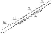
fig. 4 is a cross-sectional view of a linkage rod perspective view of the present invention.
In the figure, the reference number is 1, a shell; 2. placing the plate; 3. a through hole; 4. a drainage plate; 5. a collection box; 6. a feeding device; 7. a spraying device; 8. an electric push rod; 9. a fixing plate; 10. a first motor; 11. a driving gear; 12. a rotating rod; 13. a driven gear; 14. a fixed mount; 15. a second motor; 16. a clamping box; 17. a motion gear; 18. a linkage rod; 19. a rack; 20. a chute; 21. a guide bar; 22. a first spring; 23. a clamping block; 24. a limiting rod; 25. a second spring; 26. a first switch door; 27. a second switching door; 28. and a limiting block.
Detailed Description
As shown in FIGS. 1-4, the embodiment of the present invention provides a coating production equipment for hydraulic cylinder assembly, which comprises a housing 1, a placing plate 2 fixedly connected to the inside of the housing 1, a spraying device 7 fixedly connected to the inner sidewall of the housing 1, a feeding device 6 fixedly connected to one end of the top surface of the housing 1, a drainage plate 4 fixedly connected to the inside of the housing 1, a through hole 3 formed in the placing plate 2, a through hole 3 and the drainage plate 4 for draining the residual coating on the placing plate 2 to the lower side of the placing plate 2 through the through hole 3 and the drainage plate 4, a collecting box 5 disposed on the inner bottom wall of the housing 1, a second switch door 27 fitted with the collecting box 5 fixedly hinged to the front of the housing 1, a collecting box 5 for collecting the residual coating by disposing the collecting box 5, and a feeding device 6 fixedly connected with the spraying device 7 through a hose, the feeding device 6 and the spraying device 7 of the present invention, the material conveying device 6 comprises a material barrel, a feeding pipe and a water pump, and the spraying device 7 comprises a nozzle and a spray head.
The center fixedly connected with electric putter 8 of 1 top surface of casing, the utility model discloses electric putter 8 uses XTL-100 electric putter, electric putter 8's output fixedly connected with fixed plate 9, the first motor 10 of top surface fixedly connected with of fixed plate 9, the utility model discloses first motor 10 uses 90-90W buncher, the output fixedly connected with driving gear 11 of first motor 10, and the bottom surface of fixed plate 9 is rotated and is connected with bull stick 12, and the fixed surface of bull stick 12 is connected with driven gear 13, and casing 1's front fixed hinge has first switch door 26, and driven gear 13 and driving gear 11 looks adaptation are through setting up first switch door 26, and the person of facilitating the use seals when to the application operation to avoid coating to fly out casing 1's outside.
Bottom surface fixedly connected with mount 14 of bull stick 12, bottom surface fixedly connected with centre gripping case 16 of mount 14, the top surface fixedly connected with second motor 15 of centre gripping case 16, the utility model discloses second motor 15 uses 120GN-C motor that is just reversing, the output fixedly connected with motion gear 17 of second motor 15, the inside sliding connection of centre gripping case 16 has two gangbars 18, spout 20 has all been seted up to the inside of two gangbars 18, the equal sliding connection in inside of two spout 20 has guide bar 21, a side that two guide bar 21 kept away from each other is respectively in the both sides fixed connection of centre gripping case 16 inner wall, through setting up spout 20 and guide bar 21, slide gangbar 18 on guide bar 21 through spout 20 to promote the stability that gangbar 18 removed.
The utility model discloses the theory of operation as follows:
the first motor 10, the second motor 15 and the electric push rod 8 are all electrically connected with an external power supply, the cylinder barrel is placed above the placing plate 2, the electric push rod 8 is started, the output end of the electric push rod 8 extends out, so that the fixing plate 9 drives the clamping box 16 to descend through the rotating rod 12 and the fixing frame 14, the clamping box 16 is moved to the inside of the cylinder barrel, the second motor 15 is started, the output end of the second motor drives the moving gear 17 to rotate, the moving gear 17 is meshed with the two racks 19, the racks 19 drive the linkage rod 18 to move, the linkage rod 18 slides on the guide rod 21 through the sliding groove 20, the first spring 22 supports the linkage rod 18, the linkage rod 18 drives the clamping block 23 to move to the inner wall of the cylinder barrel, the clamping block 23 drives the limiting rod 24 to move, the limiting block 28 limits the limiting rod 24, and the second spring 25 supports the clamping block 23, possess the stable advantage of centre gripping, the effectual cylinder of having avoided rocks when the application operation, thereby influence the condition of application quality, start first motor 10, it is rotatory to drive driving gear 11 with first motor 10's output, thereby make driving gear 11 and driven gear 13 mesh mutually, thereby make driven gear 13 drive the mount 14 rotation through bull stick 12, thereby make the cylinder rotatory, and carry out the application through feeding device 6 and spraying device 7 to the surface of cylinder, the effectual application quality that promotes the cylinder, and the coating that produces when with the application flows in the inside of collecting box 5 through-hole 3 and drainage plate 4.
Claims (7)
1. The utility model provides a hydraulic cylinder subassembly application production facility, includes casing (1), its characterized in that: the inner part of the shell (1) is fixedly connected with a placing plate (2), the inner side wall of the shell (1) is fixedly connected with a spraying device (7), one end of the top surface of the shell (1) is fixedly connected with a material conveying device (6), the material conveying device (6) is fixedly communicated with the spraying device (7) through a hose, the center of the top surface of the shell (1) is fixedly connected with an electric push rod (8), the output end of the electric push rod (8) is fixedly connected with a fixing plate (9), the top surface of the fixing plate (9) is fixedly connected with a first motor (10), the output end of the first motor (10) is fixedly connected with a driving gear (11), the bottom surface of the fixing plate (9) is rotatably connected with a rotating rod (12), the outer surface of the rotating rod (12) is fixedly connected with a driven gear (13), the bottom surface of the rotating rod (12) is, the top surface fixedly connected with second motor (15) of centre gripping case (16), the output fixedly connected with motion gear (17) of second motor (15), the inside sliding connection of centre gripping case (16) has two gangbars (18), a side fixedly connected with that two gangbars (18) are close to each other and rack (19) of motion gear (17) looks adaptation, the equal fixedly connected with grip block (23) of one end that motion gear (17) were kept away from to two gangbars (18).
2. The hydraulic cylinder assembly painting production equipment of claim 1, characterized in that: the drainage plate (4) is fixedly connected to the inside of the shell (1), and the through hole (3) is formed in the placing plate (2).
3. The hydraulic cylinder assembly painting production equipment of claim 1, characterized in that: the inner bottom wall of the shell (1) is provided with a collecting box (5), and the front surface of the shell (1) is fixedly hinged with a second switch door (27) matched with the collecting box (5).
4. The hydraulic cylinder assembly painting production equipment of claim 1, characterized in that: two spout (20) have all been seted up to the inside of gangbar (18), and the equal sliding connection in inside of two spout (20) has guide bar (21), and the both sides fixed connection in centre gripping case (16) inner wall is respectively to the side that two guide bar (21) kept away from each other.
5. The hydraulic cylinder assembly coating production facility of claim 4, characterized in that: the outer surfaces of the two guide rods (21) are sleeved with first springs (22), and the two first springs (22) are located outside the linkage rod (18).
6. The hydraulic cylinder assembly painting production equipment of claim 1, characterized in that: two equal fixedly connected with gag lever post (24) in a side that grip block (23) are close to each other, the equal fixedly connected with stopper (28) of one end that grip block (23) were kept away from to two gag lever posts (24), and the equal fixedly connected with second spring (25) in a side that two stopper (28) are close to grip block (23).
7. The hydraulic cylinder assembly painting production equipment of claim 1, characterized in that: the front of the shell (1) is fixedly hinged with a first switch door (26), and the driven gear (13) is matched with the driving gear (11).
Priority Applications (1)
| Application Number | Priority Date | Filing Date | Title |
|---|---|---|---|
| CN202020722035.7U CN212397091U (en) | 2020-05-06 | 2020-05-06 | Hydraulic cylinder subassembly application production facility |
Applications Claiming Priority (1)
| Application Number | Priority Date | Filing Date | Title |
|---|---|---|---|
| CN202020722035.7U CN212397091U (en) | 2020-05-06 | 2020-05-06 | Hydraulic cylinder subassembly application production facility |
Publications (1)
| Publication Number | Publication Date |
|---|---|
| CN212397091U true CN212397091U (en) | 2021-01-26 |
Family
ID=74377131
Family Applications (1)
| Application Number | Title | Priority Date | Filing Date |
|---|---|---|---|
| CN202020722035.7U Active CN212397091U (en) | 2020-05-06 | 2020-05-06 | Hydraulic cylinder subassembly application production facility |
Country Status (1)
| Country | Link |
|---|---|
| CN (1) | CN212397091U (en) |
Cited By (2)
| Publication number | Priority date | Publication date | Assignee | Title |
|---|---|---|---|---|
| CN113843076A (en) * | 2021-11-03 | 2021-12-28 | 宁夏万泰照明科技股份有限公司 | LED lamp shade spraying equipment with powder is mended in spraying |
| CN114472015A (en) * | 2022-01-24 | 2022-05-13 | 李沁懋 | Sheet metal part spraying system |
-
2020
- 2020-05-06 CN CN202020722035.7U patent/CN212397091U/en active Active
Cited By (3)
| Publication number | Priority date | Publication date | Assignee | Title |
|---|---|---|---|---|
| CN113843076A (en) * | 2021-11-03 | 2021-12-28 | 宁夏万泰照明科技股份有限公司 | LED lamp shade spraying equipment with powder is mended in spraying |
| CN114472015A (en) * | 2022-01-24 | 2022-05-13 | 李沁懋 | Sheet metal part spraying system |
| CN114472015B (en) * | 2022-01-24 | 2024-01-30 | 中山市龙达电器有限公司 | Sheet metal part spraying system |
Similar Documents
| Publication | Publication Date | Title |
|---|---|---|
| CN212397091U (en) | Hydraulic cylinder subassembly application production facility | |
| CN210994909U (en) | Paint spraying device is used in automobile parts processing | |
| CN211161072U (en) | Cleaning device of containing barrel for processing coloring agent | |
| CN113560075B (en) | Paint spraying device with uniform rotating speed for wind power accessories | |
| CN108296069A (en) | A kind of reversible mobile phone outer casing spraying painting device | |
| CN211838609U (en) | Paint spraying device of environment-friendly printed circuit board | |
| CN211385482U (en) | Spraying device for production and processing of filter shell | |
| CN111424940B (en) | Floor paint construction robot | |
| CN210434475U (en) | A belt cleaning device for industrial chemicals reation kettle discharge gate | |
| CN208712036U (en) | A kind of furniture spray painting cleaning plant of spray head | |
| CN211073069U (en) | Hardware processing rust cleaning device | |
| CN112588652A (en) | Cable cleaning equipment for electric power construction | |
| CN115301445A (en) | Paint spraying apparatus for industrial robot manufacturing | |
| CN215429788U (en) | A rust-resistant processing apparatus for motor shaft | |
| CN112517296B (en) | Auto part coating production equipment and application method thereof | |
| CN211801869U (en) | Paint spraying apparatus is used in furniture production | |
| CN210965767U (en) | Storable push type paint roller brush | |
| CN210906709U (en) | Silver paste spraying device for ceramic blank | |
| CN210753947U (en) | Capacitor case belt cleaning device | |
| CN113019762A (en) | Paint spraying equipment and paint spraying method for manufacturing magnesium-aluminum alloy decorative lines | |
| CN217064133U (en) | Circuit board convenient to wash production | |
| CN215970899U (en) | Dust scraping device for manufacturing lacquer paintings | |
| CN212580731U (en) | Belt cleaning device is used in screw production | |
| CN218666381U (en) | Electroplating roller device | |
| CN213914384U (en) | Painting device is used in production of square hole decorative board |
Legal Events
| Date | Code | Title | Description |
|---|---|---|---|
| GR01 | Patent grant | ||
| GR01 | Patent grant |