CN212376687U - Inclined shaft spiral lifting system - Google Patents
Inclined shaft spiral lifting system Download PDFInfo
- Publication number
- CN212376687U CN212376687U CN202020694803.2U CN202020694803U CN212376687U CN 212376687 U CN212376687 U CN 212376687U CN 202020694803 U CN202020694803 U CN 202020694803U CN 212376687 U CN212376687 U CN 212376687U
- Authority
- CN
- China
- Prior art keywords
- threaded
- threaded rod
- driving module
- sleeve
- connecting ring
- Prior art date
- Legal status (The legal status is an assumption and is not a legal conclusion. Google has not performed a legal analysis and makes no representation as to the accuracy of the status listed.)
- Active
Links
Images


Abstract
The utility model relates to a spiral lifting system for an inclined shaft, which belongs to the field of underground mining equipment; providing an inclined shaft man-vehicle system which runs by adopting an internal thread pipe; the technical scheme is as follows: a slant well spiral lift system comprising: a threaded track and a transfer trolley; the threaded rail is fixed on the ground of the inclined shaft, and a transfer trolley is movably arranged on the threaded rail; the threaded track includes: the screw thread sleeve, the threaded rod, the driving module and the connecting ring; the cross section of the threaded sleeve is a C-shaped internal threaded pipe, the threaded rod is arranged in the threaded sleeve and can rotate around the central line of the threaded rod, a connecting ring is movably sleeved on the threaded rod and connected with a transfer trolley, an output shaft of the driving module is connected with the threaded rod, and a shell of the driving module is relatively fixed with the connecting ring.
Description
Technical Field
The utility model relates to a slant well spiral lift system belongs to mining equipment field in the pit.
Background
During underground mining operation, an underground inclined roadway communicated with the ground is often arranged and is used for tasks such as lifting coal and gangue, lowering equipment and equipment, lifting personnel, ventilating, draining water, filling and the like, and the inclined roadway is an inclined shaft.
When workers are transported in the inclined shaft, workers are often transported by the aid of inclined shaft man cars, and the inclined shaft man car underground transportation system has the advantages of being high in speed and convenient to use. The inclined shaft man car is lifted or lowered along the track through a cable to realize personnel transportation. In the working process, the cable is broken when the man-car in the inclined shaft walks midway, and once the fault occurs, the rope breaking protection device (brake) on the man-car in the inclined shaft is started automatically or manually, so that the aim of braking and stopping the man-car in the inclined shaft is fulfilled. However, once the cable is broken, if the cable cannot be braked in time, the speed of the people and vehicles in the inclined shaft running on the track is increased sharply, and the possibility of braking is gradually reduced due to the strong inertia of the people and vehicles in the inclined shaft, so that the people and vehicles in the inclined shaft crash into the shaft bottom, and people on the vehicles are unlikely to be broken.
At present, although various improvements are made on the man car in the inclined shaft, the braking means is complicated, and the quality of the mooring rope is improved, the tendency that the man car in the inclined shaft slips down to the bottom of the shaft after the man car in the inclined shaft breaks down cannot be fundamentally avoided, and the safety of workers of the man car in the inclined shaft cannot be effectively guaranteed.
SUMMERY OF THE UTILITY MODEL
In order to solve the technical problem, the utility model provides an adopt inclined shaft people's car system of internal thread pipe operation.
In order to achieve the technical purpose, the utility model provides a technical scheme does:
a slant well spiral lift system comprising: a threaded track and a transfer trolley; the threaded rail is fixed on the ground of the inclined shaft, and a transfer trolley is movably arranged on the threaded rail;
the threaded track includes: the screw thread sleeve, the threaded rod, the driving module and the connecting ring; the cross section of the threaded sleeve is a C-shaped internal threaded pipe, the threaded rod is arranged in the threaded sleeve and can rotate around the central line of the threaded rod, a connecting ring is movably sleeved on the threaded rod and connected with a transfer trolley, an output shaft of the driving module is connected with the threaded rod, and a shell of the driving module is relatively fixed with the connecting ring.
The inclined shaft spiral lifting system further comprises rails, and the two rails are arranged in parallel with the threaded rails.
The two sides of the transfer trolley are provided with a plurality of wheels, the wheels are provided with wheel rims, the wheels are correspondingly arranged on the two rails, and the wheel rims are in contact with the inner side surfaces of the corresponding rails.
Step shafts are coaxially fixed at two ends of the threaded rod, and external threads are arranged at the ends of the step shafts.
The end of the step shaft is connected with the driving module through a coupler.
And a bearing is fixed on the step shaft, and the outer ring of the bearing is fixedly connected with the connecting ring.
The connecting ring comprises a connecting sleeve and a connecting plate; the inner wall of the connecting sleeve is fixed with the outer ring of the bearing, and the outer diameter of the connecting sleeve is smaller than the diameter of the threaded rod.
The threaded sleeves are multiple, the threaded sleeves are sequentially connected end to form a threaded track, and the central lines of the threaded sleeves are collinear.
The transfer trolley is provided with a battery, a motor controller and a switch, the battery and the motor controller are electrically connected with the driving module, and the switch is arranged on the battery anode output bus.
The inclined shaft has a well inclination angle of 0-45 degrees.
The outer diameter of the threaded sleeve is 15-30 cm.
The inner diameter of the threaded sleeve is 7-25 cm.
The opening included angle of the threaded sleeve is not more than 150 degrees.
The threaded sleeve is 200-500 cm in length.
The motor adopts a permanent magnet stepping motor.
The lowest end of the pipe wall of the threaded sleeve is provided with a plurality of through holes, and the through holes are uniformly arranged in the threaded sleeve along the extending direction of the threaded sleeve.
Compared with the prior art, the utility model following beneficial effect has:
firstly, the utility model discloses a screw track drives the transfer car (buggy) operation, even break down, the threaded rod does to keep static relatively at the screw track, and fundamentally stops the inclined shaft people car landing shaft bottom probably.
Two, the utility model discloses a mode that screw thread track and slide rail coexist, screw thread track can provide axial effort for the transfer car (buggy), realizes the drive to the transfer car (buggy), and the slide rail provides the radial effort of screw thread track for the transfer car (buggy) simultaneously, prevents promptly that the screw rod from being unfavorable for the threaded rod to move in screw thread track after the deformation takes place for transfer car (buggy) gravity.
Drawings
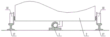
Fig. 1 is a schematic structural diagram of the present invention.
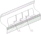
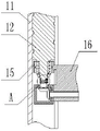
Fig. 2 is a schematic view of the installation of the threaded track of the present invention.
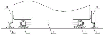
Fig. 3 is a schematic view of another screw track installation of the present invention.
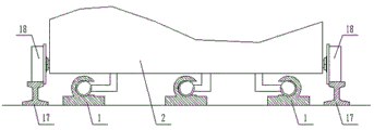
Fig. 4 is a schematic view of another screw track installation of the present invention.
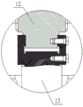
Fig. 5 is a schematic view of the internal structure of the thread track of the present invention.
Fig. 6 is a schematic view of the connection between the threaded rod, the drive module and the connection ring according to the present invention.
Fig. 7 is a schematic view of another connection between the threaded rod, the drive module and the attachment ring of the present invention.
Fig. 8 is a schematic view of the connection between the threaded rod and the driving module according to the present invention.
In the figure: the device comprises a threaded rail 1, a transfer trolley 2, a threaded sleeve 11, a threaded rod 12, a driving module 13, a connecting ring 14, a connecting sleeve 15, a connecting plate 16, a rail 17 and wheels 18.
Detailed Description
For a further understanding of the present invention, reference will now be made in detail to the following examples and embodiments, taken in conjunction with the accompanying drawings:
example 1
As shown in fig. 1, 2, 5, 6 and 8: the utility model relates to a slant spiral lift system, include: a threaded track 1 and a transfer trolley 2;
one threaded rail 1 is arranged, the threaded rail 1 is fixed on the ground of the inclined shaft, and a transfer trolley 2 is movably arranged on the threaded rail 1;
the threaded track 1 comprises: a threaded sleeve 11, a threaded rod 12, a driving module 13 and a connecting ring 14; the cross section of the threaded sleeve 11 is a C-shaped internal threaded pipe, the threaded rod 12 is arranged in the threaded sleeve 11, the threaded rod 12 can rotate around the central line of the threaded rod 12, the threaded rod 12 is movably sleeved with a connecting ring 14, the connecting ring 14 is connected with the transfer trolley 2, the output shaft of the driving module 13 is connected with the threaded rod 12, and the shell of the driving module 13 is fixed relative to the connecting ring 14.
The driving module 13 is a motor, a hydraulic motor and the like, the driving module 13 is arranged in the threaded sleeve 11, and the driving module 13 is coaxially and fixedly connected with the threaded rod 12.
The inclined shaft spiral lifting system further comprises a track 17, the two tracks 17 are arranged in parallel, the thread track 1 is arranged between the two tracks 17, and the thread track 1 is parallel to the tracks 17.
The two sides of the transfer trolley 2 are provided with a plurality of wheels 18, the wheels 18 are provided with wheel rims, the wheels 18 are correspondingly arranged on the two rails 17, and the wheel rims are in contact with the inner side surfaces of the corresponding rails 17.
Step shafts are coaxially fixed at two ends of the threaded rod 12, and external threads are arranged at the ends of the step shafts.
A bearing is fixed on the step shaft, and the outer ring of the bearing is fixedly connected with the connecting ring 14.
The connecting ring 14 comprises a connecting sleeve 15 and a connecting plate 16; the inner wall of the connecting sleeve 15 is fixed with the bearing outer ring, and the outer diameter of the connecting sleeve 15 is smaller than the diameter of the threaded rod 12.
The threaded sleeves 11 are multiple, the threaded sleeves 11 are sequentially connected end to form the threaded track 1, and the central lines of the threaded sleeves 11 are collinear.
The transfer trolley 2 is provided with a battery, a motor controller and a switch, the battery and the motor controller are electrically connected with the driving module 13, and the battery anode output bus is provided with the switch.
The inclined shaft has a well inclination angle of 0-45 degrees.
Example 2
As shown in fig. 1, 2, 7 and 8: the utility model relates to a slant spiral lift system, include: a threaded track 1 and a transfer trolley 2;
one threaded rail 1 is arranged, the threaded rail 1 is fixed on the ground of the inclined shaft, and a transfer trolley 2 is movably arranged on the threaded rail 1;
the threaded track 1 comprises: a threaded sleeve 11, a threaded rod 12, a driving module 13 and a connecting ring 14; the cross section of the threaded sleeve 11 is a C-shaped internal threaded pipe, the threaded rod 12 is arranged in the threaded sleeve 11, the threaded rod 12 can rotate around the central line of the threaded rod 12, the threaded rod 12 is movably sleeved with a connecting ring 14, the connecting ring 14 is connected with the transfer trolley 2, the output shaft of the driving module 13 is connected with the threaded rod 12, and the shell of the driving module 13 is fixed relative to the connecting ring 14.
The driving module 13 is a motor, a hydraulic motor and the like, the driving module 13 is connected with the threaded rod 12 through a commutator, the driving module 13 is fixed on the transfer trolley 2, the commutator is arranged in the threaded sleeve 11, the input shaft of the commutator is connected with the output shaft of the driving module 13, the output shaft of the commutator is connected with the threaded rod 12, and the commutator shell is relatively fixed with the connecting ring 14.
The inclined shaft spiral lifting system further comprises a track 17, the two tracks 17 are arranged in parallel, the thread track 1 is arranged between the two tracks 17, and the thread track 1 is parallel to the tracks 17.
The two sides of the transfer trolley 2 are provided with a plurality of wheels 18, the wheels 18 are provided with wheel rims, the wheels 18 are correspondingly arranged on the two rails 17, and the wheel rims are in contact with the inner side surfaces of the corresponding rails 17.
Step shafts are coaxially fixed at two ends of the threaded rod 12, and external threads are arranged at the ends of the step shafts.
A bearing is fixed on the step shaft, and the outer ring of the bearing is fixedly connected with the connecting ring 14.
The connecting ring 14 comprises a connecting sleeve 15 and a connecting plate 16; the inner wall of the connecting sleeve 15 is fixed with the bearing outer ring, and the outer diameter of the connecting sleeve 15 is smaller than the diameter of the threaded rod 12.
The threaded sleeves 11 are multiple, the threaded sleeves 11 are sequentially connected end to form the threaded track 1, and the central lines of the threaded sleeves 11 are collinear.
The transfer trolley 2 is provided with a battery, a motor controller and a switch, the battery and the motor controller are electrically connected with the driving module 13, and the battery anode output bus is provided with the switch.
The inclined shaft has a well inclination angle of 0-45 degrees.
Example 3
As shown in fig. 1, 3, 5, 6 and 8: the utility model relates to a slant spiral lift system, include: a threaded track 1 and a transfer trolley 2;
the number of the thread rails 1 is two, the thread rails 1 are fixed on the ground of an inclined shaft, and a transfer trolley 2 is movably arranged on the thread rails 1;
the threaded track 1 comprises: a threaded sleeve 11, a threaded rod 12, a driving module 13 and a connecting ring 14; the cross section of the threaded sleeve 11 is a C-shaped internal threaded pipe, the threaded rod 12 is arranged in the threaded sleeve 11, the threaded rod 12 can rotate around the central line of the threaded rod 12, the threaded rod 12 is movably sleeved with a connecting ring 14, the connecting ring 14 is connected with the transfer trolley 2, the output shaft of the driving module 13 is connected with the threaded rod 12, and the shell of the driving module 13 is fixed relative to the connecting ring 14.
The driving module 13 is a motor, a hydraulic motor and the like, the driving module 13 is arranged in the threaded sleeve 11, and the driving module 13 is coaxially and fixedly connected with the threaded rod 12.
The inclined shaft spiral lifting system further comprises a track 17, wherein the two tracks 17 are arranged in parallel, the two thread tracks 1 are arranged between the two tracks 17, and the thread tracks 1 are parallel to the tracks 17.
The two sides of the transfer trolley 2 are provided with a plurality of wheels 18, the wheels 18 are provided with wheel rims, the wheels 18 are correspondingly arranged on the two rails 17, and the wheel rims are in contact with the inner side surfaces of the corresponding rails 17.
Step shafts are coaxially fixed at two ends of the threaded rod 12, and external threads are arranged at the ends of the step shafts.
A bearing is fixed on the step shaft, and the outer ring of the bearing is fixedly connected with the connecting ring 14.
The connecting ring 14 comprises a connecting sleeve 15 and a connecting plate 16; the inner wall of the connecting sleeve 15 is fixed with the bearing outer ring, and the outer diameter of the connecting sleeve 15 is smaller than the diameter of the threaded rod 12.
The threaded sleeves 11 are multiple, the threaded sleeves 11 are sequentially connected end to form the threaded track 1, and the central lines of the threaded sleeves 11 are collinear.
The transfer trolley 2 is provided with a battery, a motor controller and a switch, the battery and the motor controller are electrically connected with the driving module 13, and the battery anode output bus is provided with the switch.
The inclined shaft has a well inclination angle of 0-45 degrees.
Example 4
As shown in fig. 1, 3, 7 and 8: the utility model relates to a slant spiral lift system, include: a threaded track 1 and a transfer trolley 2;
the number of the thread rails 1 is two, the thread rails 1 are fixed on the ground of an inclined shaft, and a transfer trolley 2 is movably arranged on the thread rails 1;
the threaded track 1 comprises: a threaded sleeve 11, a threaded rod 12, a driving module 13 and a connecting ring 14; the cross section of the threaded sleeve 11 is a C-shaped internal threaded pipe, the threaded rod 12 is arranged in the threaded sleeve 11, the threaded rod 12 can rotate around the central line of the threaded rod 12, the threaded rod 12 is movably sleeved with a connecting ring 14, the connecting ring 14 is connected with the transfer trolley 2, the output shaft of the driving module 13 is connected with the threaded rod 12, and the shell of the driving module 13 is fixed relative to the connecting ring 14.
The driving module 13 is a motor, a hydraulic motor and the like, the driving module 13 is connected with the threaded rod 12 through a commutator, the driving module 13 is fixed on the transfer trolley 2, the commutator is arranged in the threaded sleeve 11, the input shaft of the commutator is connected with the output shaft of the driving module 13, the output shaft of the commutator is connected with the threaded rod 12, and the commutator shell is relatively fixed with the connecting ring 14.
The inclined shaft spiral lifting system further comprises a track 17, the two tracks 17 are arranged in parallel, the two thread tracks 1 are arranged between the two tracks 17, and the thread tracks 1 are parallel to the tracks 17.
The two sides of the transfer trolley 2 are provided with a plurality of wheels 18, the wheels 18 are provided with wheel rims, the wheels 18 are correspondingly arranged on the two rails 17, and the wheel rims are in contact with the inner side surfaces of the corresponding rails 17.
Step shafts are coaxially fixed at two ends of the threaded rod 12, and external threads are arranged at the ends of the step shafts.
A bearing is fixed on the step shaft, and the outer ring of the bearing is fixedly connected with the connecting ring 14.
The connecting ring 14 comprises a connecting sleeve 15 and a connecting plate 16; the inner wall of the connecting sleeve 15 is fixed with the bearing outer ring, and the outer diameter of the connecting sleeve 15 is smaller than the diameter of the threaded rod 12.
The threaded sleeves 11 are multiple, the threaded sleeves 11 are sequentially connected end to form the threaded track 1, and the central lines of the threaded sleeves 11 are collinear.
The transfer trolley 2 is provided with a battery, a motor controller and a switch, the battery and the motor controller are electrically connected with the driving module 13, and the battery anode output bus is provided with the switch.
The inclined shaft has a well inclination angle of 0-45 degrees.
Example 5
As shown in fig. 1, 4, 5, 6 and 8: the utility model relates to a slant spiral lift system, include: a threaded track 1 and a transfer trolley 2;
the number of the threaded rails 1 is three, the threaded rails 1 are fixed on the ground of the inclined shaft, and a transfer trolley 2 is movably arranged on the threaded rails 1;
the threaded track 1 comprises: a threaded sleeve 11, a threaded rod 12, a driving module 13 and a connecting ring 14; the cross section of the threaded sleeve 11 is a C-shaped internal threaded pipe, the threaded rod 12 is arranged in the threaded sleeve 11, the threaded rod 12 can rotate around the central line of the threaded rod 12, the threaded rod 12 is movably sleeved with a connecting ring 14, the connecting ring 14 is connected with the transfer trolley 2, the output shaft of the driving module 13 is connected with the threaded rod 12, and the shell of the driving module 13 is fixed relative to the connecting ring 14.
The driving module 13 is a motor, a hydraulic motor and the like, the driving module 13 is arranged in the threaded sleeve 11, and the driving module 13 is coaxially and fixedly connected with the threaded rod 12.
The inclined shaft spiral lifting system further comprises a track 17, wherein the two tracks 17 are arranged in parallel, the three thread tracks 1 are arranged between the two tracks 17, and the thread tracks 1 are parallel to the tracks 17.
The two sides of the transfer trolley 2 are provided with a plurality of wheels 18, the wheels 18 are provided with wheel rims, the wheels 18 are correspondingly arranged on the two rails 17, and the wheel rims are in contact with the inner side surfaces of the corresponding rails 17.
Step shafts are coaxially fixed at two ends of the threaded rod 12, and external threads are arranged at the ends of the step shafts.
A bearing is fixed on the step shaft, and the outer ring of the bearing is fixedly connected with the connecting ring 14.
The connecting ring 14 comprises a connecting sleeve 15 and a connecting plate 16; the inner wall of the connecting sleeve 15 is fixed with the bearing outer ring, and the outer diameter of the connecting sleeve 15 is smaller than the diameter of the threaded rod 12.
The threaded sleeves 11 are multiple, the threaded sleeves 11 are sequentially connected end to form the threaded track 1, and the central lines of the threaded sleeves 11 are collinear.
The transfer trolley 2 is provided with a battery, a motor controller and a switch, the battery and the motor controller are electrically connected with the driving module 13, and the battery anode output bus is provided with the switch.
The inclined shaft has a well inclination angle of 0-45 degrees.
Example 6
As shown in fig. 1, 4, 7 and 8: the utility model relates to a slant spiral lift system, include: a threaded track 1 and a transfer trolley 2;
the number of the threaded rails 1 is three, the threaded rails 1 are fixed on the ground of the inclined shaft, and a transfer trolley 2 is movably arranged on the threaded rails 1;
the threaded track 1 comprises: a threaded sleeve 11, a threaded rod 12, a driving module 13 and a connecting ring 14; the cross section of the threaded sleeve 11 is a C-shaped internal threaded pipe, the threaded rod 12 is arranged in the threaded sleeve 11, the threaded rod 12 can rotate around the central line of the threaded rod 12, the threaded rod 12 is movably sleeved with a connecting ring 14, the connecting ring 14 is connected with the transfer trolley 2, the output shaft of the driving module 13 is connected with the threaded rod 12, and the shell of the driving module 13 is fixed relative to the connecting ring 14.
The driving module 13 is a motor, a hydraulic motor and the like, the driving module 13 is connected with the threaded rod 12 through a commutator, the driving module 13 is fixed on the transfer trolley 2, the commutator is arranged in the threaded sleeve 11, the input shaft of the commutator is connected with the output shaft of the driving module 13, the output shaft of the commutator is connected with the threaded rod 12, and the commutator shell is relatively fixed with the connecting ring 14.
The inclined shaft spiral lifting system further comprises a track 17, wherein the two tracks 17 are arranged in parallel, the three thread tracks 1 are arranged between the two tracks 17, and the thread tracks 1 are parallel to the tracks 17.
The two sides of the transfer trolley 2 are provided with a plurality of wheels 18, the wheels 18 are provided with wheel rims, the wheels 18 are correspondingly arranged on the two rails 17, and the wheel rims are in contact with the inner side surfaces of the corresponding rails 17.
Step shafts are coaxially fixed at two ends of the threaded rod 12, and external threads are arranged at the ends of the step shafts.
A bearing is fixed on the step shaft, and the outer ring of the bearing is fixedly connected with the connecting ring 14.
The connecting ring 14 comprises a connecting sleeve 15 and a connecting plate 16; the inner wall of the connecting sleeve 15 is fixed with the bearing outer ring, and the outer diameter of the connecting sleeve 15 is smaller than the diameter of the threaded rod 12.
The threaded sleeves 11 are multiple, the threaded sleeves 11 are sequentially connected end to form the threaded track 1, and the central lines of the threaded sleeves 11 are collinear.
The transfer trolley 2 is provided with a battery, a motor controller and a switch, the battery and the motor controller are electrically connected with the driving module 13, and the battery anode output bus is provided with the switch.
The inclined shaft has a well inclination angle of 0-45 degrees.
The utility model discloses specific operation as follows:
the personnel take the transfer trolley 2, start the driving motor 13, realize the threaded rod 12 and move in the threaded sleeve 11, two driving motors 13 must keep unanimous, the threaded rod 12 realizes moving along the threaded sleeve 11 axial while moving, drives the transfer trolley 2 and reciprocates in the inclined shaft, realizes the purpose of transporting personnel.
The above embodiments are merely illustrative of the principles and effects of the present invention, and are not intended to limit the present invention. It will be apparent to those skilled in the art that modifications and improvements can be made to the above-described embodiments without departing from the spirit and scope of the invention. Accordingly, it will be appreciated that those skilled in the art, upon attaining an understanding of the foregoing may readily produce alterations to, variations of, and equivalents to these embodiments without departing from the spirit and scope of the present invention as defined by the appended claims.
Claims (9)
1. A slant well spiral lifting system comprising: a threaded track (1) and a transfer trolley (2); the threaded rail (1) is fixed on the ground of the inclined shaft, and a transfer trolley (2) is movably arranged on the threaded rail (1);
the threaded rail (1) comprises: the screw thread sleeve (11), the screw thread rod (12), the driving module (13) and the connecting ring (14); the cross section of the threaded sleeve (11) is a C-shaped internal threaded pipe, the threaded rod (12) is arranged in the threaded sleeve (11), the threaded rod (12) can rotate around the central line of the threaded rod, the threaded rod (12) is movably sleeved with a connecting ring (14), the connecting ring (14) is connected with the transfer trolley (2), the output shaft of the driving module (13) is connected with the threaded rod (12), and the shell of the driving module (13) is fixed relative to the connecting ring (14).
2. The slant well screw lift system of claim 1, wherein: the inclined shaft spiral lifting system further comprises rails (17), and the two rails (17) are arranged in parallel with the threaded rail (1).
3. The slant well screw lift system of claim 2, wherein: the two sides of the transfer trolley (2) are provided with a plurality of wheels (18), the wheels (18) are provided with wheel rims, the wheels (18) are correspondingly arranged on the two rails (17), and the wheel rims are in contact with the inner side surfaces of the corresponding rails (17).
4. A deviated well screw lift system according to claim 1 or 3 wherein: step shafts are coaxially fixed at two ends of the threaded rod (12), and external threads are arranged at the ends of the step shafts.
5. The slant well screw lift system of claim 4, wherein: and a bearing is fixed on the step shaft, and the outer ring of the bearing is fixedly connected with a connecting ring (14).
6. A deviated well screw lift system according to claim 1 or 5 wherein: the connecting ring (14) comprises a connecting sleeve (15) and a connecting plate (16); the inner wall of the connecting sleeve (15) is fixed with the bearing outer ring, and the outer diameter of the connecting sleeve (15) is smaller than the diameter of the threaded rod (12).
7. A slant entry spiral lifting system as defined in claim 1, wherein: the threaded sleeves (11) are multiple, the threaded sleeves (11) are sequentially connected end to form the threaded track (1), and the central lines of the threaded sleeves (11) are collinear.
8. The slant well screw lift system of claim 1, wherein: the transfer trolley (2) is provided with a battery, a motor controller and a switch, the battery and the motor controller are electrically connected with the driving module (13), and the battery anode output bus is provided with the switch.
9. The slant well screw lift system of claim 1, wherein: the inclined shaft has a well inclination angle of 0-45 degrees.
Priority Applications (1)
| Application Number | Priority Date | Filing Date | Title |
|---|---|---|---|
| CN202020694803.2U CN212376687U (en) | 2020-04-30 | 2020-04-30 | Inclined shaft spiral lifting system |
Applications Claiming Priority (1)
| Application Number | Priority Date | Filing Date | Title |
|---|---|---|---|
| CN202020694803.2U CN212376687U (en) | 2020-04-30 | 2020-04-30 | Inclined shaft spiral lifting system |
Publications (1)
| Publication Number | Publication Date |
|---|---|
| CN212376687U true CN212376687U (en) | 2021-01-19 |
Family
ID=74161899
Family Applications (1)
| Application Number | Title | Priority Date | Filing Date |
|---|---|---|---|
| CN202020694803.2U Active CN212376687U (en) | 2020-04-30 | 2020-04-30 | Inclined shaft spiral lifting system |
Country Status (1)
| Country | Link |
|---|---|
| CN (1) | CN212376687U (en) |
-
2020
- 2020-04-30 CN CN202020694803.2U patent/CN212376687U/en active Active
Similar Documents
| Publication | Publication Date | Title |
|---|---|---|
| CN206129300U (en) | Shield constructs to start uses section of jurisdiction conveyer | |
| US9926171B2 (en) | Embedded safety elevator | |
| CN206267586U (en) | A kind of vertical garage Special-purpose lifting device | |
| CN212376687U (en) | Inclined shaft spiral lifting system | |
| CN204727458U (en) | A kind of European hoisting crane crane carriage | |
| CN100352711C (en) | Screw-pushing type climbing train | |
| CN205076600U (en) | Anti -falling protection device of elevator | |
| CN111379587A (en) | Inclined shaft spiral lifting system | |
| CN215854813U (en) | Novel haulage winch | |
| CN101863419B (en) | Multipurpose crane trolly | |
| CN209974041U (en) | Elevator capable of reducing roof construction amount | |
| CN210763773U (en) | Lifting device for be used for construction | |
| CN210505272U (en) | Pneumatic monorail crane | |
| CN107542297A (en) | Garage lifting system | |
| CN203529666U (en) | Embedded safety lifting elevator | |
| CN205894791U (en) | Perpendicular circulating stereo garage actuating system | |
| CN201002929Y (en) | Small-sized road maintenance machinery hoisting transporting vehicle | |
| CN205858171U (en) | A kind of elevator pit climbing ladder apparatus | |
| CN114275651B (en) | Energy-saving high-speed elevator | |
| CN204917577U (en) | Energy -conserving elevator hauler of alternative formula | |
| CN205935819U (en) | Mechanical type is lifting machine traction device for parking equipment | |
| CN217947452U (en) | Shaft construction lifting device | |
| CN212403119U (en) | Mine cage chair replacing device | |
| CN212475680U (en) | Fixing mechanism of operating panel maintenance device | |
| CN217151823U (en) | Detachable multipurpose ladder vehicle |
Legal Events
| Date | Code | Title | Description |
|---|---|---|---|
| GR01 | Patent grant | ||
| GR01 | Patent grant |