CN212369997U - Raw material mixing device based on protection film production - Google Patents
Raw material mixing device based on protection film production Download PDFInfo
- Publication number
- CN212369997U CN212369997U CN202020601621.6U CN202020601621U CN212369997U CN 212369997 U CN212369997 U CN 212369997U CN 202020601621 U CN202020601621 U CN 202020601621U CN 212369997 U CN212369997 U CN 212369997U
- Authority
- CN
- China
- Prior art keywords
- stirring
- shaft
- stirring shaft
- tank
- bevel gear
- Prior art date
- Legal status (The legal status is an assumption and is not a legal conclusion. Google has not performed a legal analysis and makes no representation as to the accuracy of the status listed.)
- Expired - Fee Related
Links
Images

Abstract
The utility model discloses a raw material mixing device based on protection film production, including the agitator tank, the agitator tank sets up on the top of support, and the output of motor is connected with the (mixing) shaft, and the bottom of (mixing) shaft extends to the inside of agitator tank, and the cover is equipped with main stirring rake on the bottom of (mixing) shaft, and the bottom of (mixing) shaft is connected with vice agitator shaft through the transmission case; the bottom end of the stirring shaft extends into the transmission box and is rotationally connected with the transmission box, the bottom end of the stirring shaft is connected with the driving bevel gear, driven bevel gears are respectively arranged on two sides of the driving bevel gear and are respectively meshed with the driven bevel gears, one end of each driven bevel gear is connected with the auxiliary stirring shaft, the auxiliary stirring shaft penetrates through the side wall of the transmission box and is rotationally connected with the transmission box, and auxiliary stirring paddles are sleeved on the auxiliary stirring shaft; the utility model discloses material to the agitator tank evenly stirs to improved the efficiency of protection film raw material stirring greatly, simultaneously, also avoided the material adhesion to remain the advantage on the inner wall of jar.
Description
Technical Field
The utility model belongs to the technical field of the protection film production, a raw material mixing device is related to, specifically is a raw material mixing device based on protection film production.
Background
In the production process of the protective film, the raw materials are fully mixed and stirred.
However, in the prior art, a single stirring shaft is usually adopted to be provided with a stirring paddle for stirring, so that the stirring speed of the material at the bottom in the tank is low, the flowability is poor, and the material at the bottom cannot be fully stirred; because the viscidity that the nature of protection film raw materials influenced the material is bigger for in the stirring process, there is a large amount of materials to splash and the adhesion on the inner wall of agitator tank, and, when unloading, the material also easy adhesion on the inner wall of agitator tank, greatly reduced the production efficiency's of protection film problem.
SUMMERY OF THE UTILITY MODEL
The utility model aims to solve the problems that in the prior art, a single stirring shaft is usually provided with a stirring paddle for stirring, so that the stirring speed of the material at the bottom in the tank is low, the flowability is poor, and the material at the bottom cannot be stirred sufficiently; because the viscidity that the nature of protection film raw materials influenced the material is bigger for in the stirring process, there is a large amount of materials to splash and the adhesion on the inner wall of agitator tank, and, when unloading, the material also easy adhesion on the inner wall of agitator tank, greatly reduced the production efficiency's of protection film problem, and provide a raw materials mixing arrangement based on protection film production.
The purpose of the utility model can be realized by the following technical scheme:
a raw material mixing device based on protective film production comprises a stirring tank, wherein the stirring tank is arranged at the top end of a support, a motor is arranged at the top end of the stirring tank, the output end of the motor is connected with a stirring shaft, the bottom end of the stirring shaft extends into the stirring tank, a main stirring paddle is sleeved on the bottom of the stirring shaft, and the bottom end of the stirring shaft is connected with an auxiliary stirring shaft through a transmission case;
the transmission case passes through the back shaft and installs on the inside bottom surface of agitator tank, the bottom of (mixing) shaft extends to the inside of transmission case to rotate with the transmission case and be connected, the bottom and the drive bevel gear of (mixing) shaft are connected, drive bevel gear's both sides are provided with driven bevel gear respectively, and be connected with driven bevel gear meshing respectively, driven bevel gear's one end and vice agitator shaft are connected, vice (mixing) shaft passes the lateral wall of transmission case, and be connected with the transmission case rotation, the cover is equipped with vice stirring rake on the vice (mixing) shaft.
Preferably, the top end of the stirring shaft is sleeved with a scraping assembly, and the scraping assembly comprises a connecting cross rod, a connecting vertical rod and a scraping plate.
Preferably, the connecting cross rods are symmetrically arranged along the stirring shaft and are sleeved on the stirring shaft through sleeves, the connecting vertical rods are vertically arranged on the other sides of the connecting cross rods, the scraping plates are arranged on the inner walls, close to the stirring tank, of the connecting vertical rods, and the scraping plates are abutted to the inner walls of the stirring tank.
Preferably, the side wall of the connecting vertical rod far away from the scraper is provided with side stirring paddles, and the side stirring paddles are arranged in parallel to form a plurality of groups.
Preferably, the top of agitator tank is provided with the charge door, and the bottom of agitator tank is provided with the discharging pipe.
Compared with the prior art, the beneficial effects of the utility model are that: when the stirring device works, raw materials required by production of a protective film are added into a stirring tank through a charging hole, then a motor is started to work to drive a stirring shaft and a main stirring paddle on the stirring shaft to rotate, so that the main stirring paddle stirs middle materials in the stirring tank, meanwhile, the stirring shaft rotates to drive a driving bevel gear in a transmission box to rotate, the driving bevel gear drives a driven bevel gear through meshing action, the driven bevel gear drives an auxiliary stirring shaft and an auxiliary stirring paddle on the stirring shaft to rotate, so that the auxiliary stirring paddle at the bottom can effectively stir the materials at the bottom of the stirring tank, the materials in the stirring tank are uniformly stirred, the stirring efficiency of raw materials of the protective film is greatly improved, the problems that in the prior art, the stirring paddle is arranged on a single stirring shaft to stir the materials, the stirring speed of the materials at the bottom in the tank is slow, and the flowability is, the bottom materials can not be fully stirred;
the (mixing) shaft is in the pivoted, the drive is connected the horizontal pole and is connected the montant and rotate, make the scraper blade of connecting on the montant scrape the material to the inner wall of agitator tank, and simultaneously, the side stirring rake that sets up on the connection montant can stir the material of agitator tank avris, thereby solved among the prior art, because the stickness that the nature of protection film raw materials influences the material is bigger than great, make at the stirring in-process, there is a large amount of materials to splash and the adhesion on the inner wall of agitator tank, and, when unloading, the material also easy adhesion is on the inner wall of agitator tank, greatly reduced the production efficiency's of protection film problem.
Drawings
In order to facilitate understanding for those skilled in the art, the present invention will be further described with reference to the accompanying drawings.
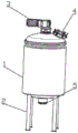
Fig. 1 is a schematic view of the overall three-dimensional structure of the present invention.
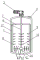
Fig. 2 is a schematic structural diagram of the interior of the stirring tank of the present invention.
Fig. 3 is a schematic structural diagram of the interior of the middle transmission case of the present invention.
In the figure: 1. a stirring tank; 2. a support; 3. a motor; 4. a feed inlet; 5. a discharge pipe; 6. a stirring shaft; 7. connecting the cross bars; 8. connecting the vertical rods; 9. a side stirring paddle; 10. a main stirring paddle; 11. a transmission case; 12. an auxiliary stirring paddle; 13. an auxiliary stirring shaft; 14. a drive bevel gear; 15. a driven bevel gear; 16. a support shaft; 17. a scraper.
Detailed Description
The technical solution of the present invention will be described clearly and completely with reference to the following embodiments, and it should be understood that the described embodiments are only a part of the embodiments of the present invention, and not all of the embodiments. Based on the embodiments of the present invention, all other embodiments obtained by a person of ordinary skill in the art without creative efforts belong to the protection scope of the present invention.
Referring to fig. 1-3, a raw material mixing device based on protective film production comprises a stirring tank 1, wherein the stirring tank 1 is arranged at the top end of a support 2, a motor 3 is arranged at the top end of the stirring tank 1, the output end of the motor 3 is connected with a stirring shaft 6, the bottom end of the stirring shaft 6 extends into the stirring tank 1, a main stirring paddle 10 is sleeved at the bottom of the stirring shaft 6, and the bottom end of the stirring shaft 6 is connected with an auxiliary stirring shaft 13 through a transmission box 11;
the stirring tank is characterized in that a transmission box 11 is installed on the inner bottom surface of a stirring tank 1 through a support shaft 16, the bottom end of a stirring shaft 6 extends into the transmission box 11 and is rotatably connected with the transmission box 11, the bottom end of the stirring shaft 6 is connected with a driving bevel gear 14, driven bevel gears 15 are respectively arranged on two sides of the driving bevel gear 14 and are respectively meshed with the driven bevel gears 15, one end of each driven bevel gear 15 is connected with an auxiliary stirring shaft 13, the auxiliary stirring shafts 13 penetrate through the side wall of the transmission box 11 and are rotatably connected with the transmission box 11, auxiliary stirring paddles 13 are sleeved on the auxiliary stirring shafts 13, a motor 3 is started to work to drive the stirring shaft 6 and main stirring paddles 10 on the stirring shaft 6 to rotate, so that middle materials in the stirring tank 1 are stirred by column stirring paddles 10, meanwhile, the stirring shaft 6 rotates to drive the driving bevel gear 14 in the transmission box 11 to rotate, driven bevel gear 15 drives vice (mixing) shaft 13 and vice stirring paddle 12 on the vice (mixing) shaft 13 and rotates, thereby make the vice stirring paddle 12 that is located the bottom can the effectual material of 1 bottoms of agitator tank stir, thereby make the material even stirring to agitator tank 1, and the efficiency of protection film raw materials stirring has been improved greatly, among the prior art has been solved, it stirs to set up the stirring paddle on the single (mixing) shaft usually to adopt, make the material stirring speed of bottom in the jar slower, it is not good to lead to mobility, make the bottom material can not carry out the problem of intensive mixing.
The top end of the stirring shaft 6 is sleeved with a scraping component, and the scraping component comprises a connecting cross rod 7, a connecting vertical rod 8 and a scraping plate 17.
Connecting horizontal pole 17 sets up along (mixing) shaft 6 symmetry to establish on (mixing) shaft 6 through the sleeve pipe cover, connecting horizontal pole 17's the vertical connection montant 8 that is provided with of opposite side, connecting montant 8 and being provided with scraper blade 17 on being close to agitator tank 1's the inner wall, scraper blade 17 and agitator tank 1's inner wall butt.
Connect montant 8 and keep away from being provided with side stirring rake 9 on scraper blade 17's the lateral wall, side stirring rake 9 is provided with the multiunit side by side, the (mixing) shaft 6 is in the pivoted, drive and connect horizontal pole 7 and connect montant 8 and rotate, make scraper blade 17 on the connection montant 8 scrape the material to agitator tank 1's inner wall, and simultaneously, the side stirring rake 9 that sets up on the connection montant 8 can stir the material of 1 avris of agitator tank, thereby solved among the prior art, because the viscidity of the nature influence material of protection film raw materials is bigger, make at the stirring in-process, there is a large amount of materials to splash and the adhesion on agitator tank 1's inner wall, and, when unloading, the material also easy adhesion is on agitator tank 1's inner wall, greatly reduced the production efficiency's of protection.
The top of agitator tank 1 is provided with charge door 4, and the bottom of agitator tank 1 is provided with discharging pipe 5.
The utility model discloses a theory of operation: when the stirring device works, raw materials required by production of a protective film are added into the stirring tank 1 through the feed inlet 4, then the motor 3 is started to work to drive the stirring shaft 6 and the main stirring paddle 10 on the stirring shaft 6 to rotate, so that the column stirring paddle 10 stirs middle materials in the stirring tank 1, meanwhile, the stirring shaft 6 rotates to drive the driving bevel gear 14 in the transmission box 11 to rotate, the driving bevel gear 14 drives the driven bevel gear 15 through meshing, the driven bevel gear 15 drives the auxiliary stirring shaft 13 and the auxiliary stirring paddle 12 on the auxiliary stirring shaft 13 to rotate, so that the auxiliary stirring paddle 12 at the bottom can effectively stir the materials at the bottom of the stirring tank 1, thereby uniformly stirring the materials in the stirring tank 1, greatly improving the stirring efficiency of the raw materials of the protective film, and solving the problem that in the prior art, the stirring paddles are usually arranged on a single stirring shaft to stir, the material at the bottom of the tank is stirred at a low speed, so that the fluidity is poor, and the material at the bottom cannot be stirred sufficiently;
(mixing) shaft 6 is in the pivoted, the drive is connected horizontal pole 7 and is connected montant 8 and rotate, make scraper blade 17 on the connection montant 8 scrape the material to the inner wall of agitator tank 1, and simultaneously, the side stirring rake 9 that sets up on the connection montant 8 can stir the material of 1 avris of agitator tank, thereby solved among the prior art, because the stickness of the nature influence material of protection film raw materials is bigger, make at the stirring in-process, there is a large amount of materials to splash and the adhesion on the inner wall of agitator tank 1, and, when unloading, the material also easy adhesion is on the inner wall of agitator tank 1, greatly reduced the production efficiency's of protection film problem.
The preferred embodiments of the present invention disclosed above are intended only to help illustrate the present invention. The preferred embodiments are not exhaustive and do not limit the invention to the precise embodiments disclosed. Obviously, many modifications and variations are possible in light of the above teaching. The embodiments were chosen and described in order to best explain the principles of the invention and its practical applications, to thereby enable others skilled in the art to best understand the invention for and utilize the invention. The present invention is limited only by the claims and their full scope and equivalents.
Claims (5)
1. The utility model provides a raw materials mixing arrangement based on protection film production which characterized in that: the stirring device comprises a stirring tank (1), wherein the stirring tank (1) is arranged at the top end of a support (2), a motor (3) is arranged at the top end of the stirring tank (1), the output end of the motor (3) is connected with a stirring shaft (6), the bottom end of the stirring shaft (6) extends into the stirring tank (1), a main stirring paddle (10) is sleeved on the bottom of the stirring shaft (6), and the bottom end of the stirring shaft (6) is connected with an auxiliary stirring shaft (13) through a transmission box (11);
the transmission case (11) is installed on the bottom surface of the inner part of the stirring tank (1) through a support shaft (16), the bottom end of the stirring shaft (6) extends to the inner part of the transmission case (11) and is rotationally connected with the transmission case (11), the bottom end of the stirring shaft (6) is connected with a driving bevel gear (14), driven bevel gears (15) are respectively arranged on two sides of the driving bevel gear (14) and are respectively meshed with the driven bevel gears (15), one end of each driven bevel gear (15) is connected with an auxiliary stirring shaft (13), the auxiliary stirring shaft (13) penetrates through the side wall of the transmission case (11) and is rotationally connected with the transmission case (11), and auxiliary stirring paddles (12) are sleeved on the auxiliary stirring shaft (13).
2. The raw material mixing device based on protective film production as claimed in claim 1, wherein the top end of the stirring shaft (6) is sleeved with a scraping component, and the scraping component comprises a connecting cross rod (7), a connecting vertical rod (8) and a scraping plate (17).
3. The raw material mixing device based on protection film production as claimed in claim 1, wherein the connecting cross rods (7) are symmetrically arranged along the stirring shaft (6) and sleeved on the stirring shaft (6) through sleeves, the connecting vertical rods (8) are vertically arranged on the other sides of the connecting cross rods (7), the scraping plates (17) are arranged on the inner walls of the connecting vertical rods (8) close to the stirring tank (1), and the scraping plates (17) are abutted to the inner walls of the stirring tank (1).
4. A raw material mixing device based on protective film production according to claim 2, characterized in that the side wall of the connecting vertical rod (8) far away from the scraper (17) is provided with side stirring paddles (9), and the side stirring paddles (9) are arranged in parallel in multiple groups.
5. A raw material mixing device based on protective film production according to claim 1, characterized in that the top of the stirring tank (1) is provided with a feed inlet (4), and the bottom of the stirring tank (1) is provided with a discharge pipe (5).
Priority Applications (1)
| Application Number | Priority Date | Filing Date | Title |
|---|---|---|---|
| CN202020601621.6U CN212369997U (en) | 2020-04-21 | 2020-04-21 | Raw material mixing device based on protection film production |
Applications Claiming Priority (1)
| Application Number | Priority Date | Filing Date | Title |
|---|---|---|---|
| CN202020601621.6U CN212369997U (en) | 2020-04-21 | 2020-04-21 | Raw material mixing device based on protection film production |
Publications (1)
| Publication Number | Publication Date |
|---|---|
| CN212369997U true CN212369997U (en) | 2021-01-19 |
Family
ID=74160611
Family Applications (1)
| Application Number | Title | Priority Date | Filing Date |
|---|---|---|---|
| CN202020601621.6U Expired - Fee Related CN212369997U (en) | 2020-04-21 | 2020-04-21 | Raw material mixing device based on protection film production |
Country Status (1)
| Country | Link |
|---|---|
| CN (1) | CN212369997U (en) |
Cited By (2)
| Publication number | Priority date | Publication date | Assignee | Title |
|---|---|---|---|---|
| CN113681746A (en) * | 2021-08-23 | 2021-11-23 | 中国万宝工程有限公司 | High-efficient plastify forming device of energetic material |
| CN115364725A (en) * | 2022-09-22 | 2022-11-22 | 石狮市凌峰漂染织造有限公司 | Liquid raw material stirring device for textile fabric processing |
-
2020
- 2020-04-21 CN CN202020601621.6U patent/CN212369997U/en not_active Expired - Fee Related
Cited By (2)
| Publication number | Priority date | Publication date | Assignee | Title |
|---|---|---|---|---|
| CN113681746A (en) * | 2021-08-23 | 2021-11-23 | 中国万宝工程有限公司 | High-efficient plastify forming device of energetic material |
| CN115364725A (en) * | 2022-09-22 | 2022-11-22 | 石狮市凌峰漂染织造有限公司 | Liquid raw material stirring device for textile fabric processing |
Similar Documents
| Publication | Publication Date | Title |
|---|---|---|
| CN212369997U (en) | Raw material mixing device based on protection film production | |
| CN214716322U (en) | Coating processing workshop prevents agitating unit that coating subsides | |
| CN207546372U (en) | The raw material Two-way Cycle agitation mixer of composite heat transfer | |
| CN212021282U (en) | A melting material modification blending device for production of liquid traditional chinese medicine wrapping bag | |
| CN216458776U (en) | Processing mixing system | |
| CN216499020U (en) | Waterborne dust bonding material preparation facilities | |
| CN216497634U (en) | Ore dressing is with concentrated machine of center drive | |
| CN214416174U (en) | Agitating unit of air entrainment brick thick liquids agitator tank | |
| CN213995741U (en) | Composite scraper stirrer | |
| CN212119863U (en) | Agitating unit is used in laundry liquid production | |
| CN213854143U (en) | Energy-conserving disconnect-type mud mixer | |
| CN206642652U (en) | A kind of stirring structure and the blending tank for including it | |
| CN220802772U (en) | Mixing arrangement of morchella culture medium | |
| CN214514312U (en) | High-efficient rabbling mechanism | |
| CN219631174U (en) | Mixing device for processing low-starch shrimp and crab feed with uniform stirring | |
| CN217834260U (en) | Mixing and stirring equipment for civil synthetic material | |
| CN219722548U (en) | Emulsifying device for cosmetic production | |
| CN215654846U (en) | Multistation ink mixer | |
| CN220517233U (en) | Pre-dispersion master batch hydraulic high-speed mixer | |
| CN220609997U (en) | Stirring device for preparing fish skin collagen | |
| CN214915213U (en) | Preserved szechuan pickle mixer | |
| CN218530615U (en) | Petrochemical auxiliary agent production agitating unit | |
| CN218249618U (en) | Homogeneity device is used in floor paint coating production and processing | |
| CN212942633U (en) | Automatic blending device of crude oil additive concentration | |
| CN220478620U (en) | Quick compound mixing equipment for carbon materials |
Legal Events
| Date | Code | Title | Description |
|---|---|---|---|
| GR01 | Patent grant | ||
| GR01 | Patent grant | ||
| CF01 | Termination of patent right due to non-payment of annual fee | ||
| CF01 | Termination of patent right due to non-payment of annual fee |
Granted publication date: 20210119 |