CN212340893U - Hardness detection device for high-hardness wear-resistant floor - Google Patents
Hardness detection device for high-hardness wear-resistant floor Download PDFInfo
- Publication number
- CN212340893U CN212340893U CN202021147999.XU CN202021147999U CN212340893U CN 212340893 U CN212340893 U CN 212340893U CN 202021147999 U CN202021147999 U CN 202021147999U CN 212340893 U CN212340893 U CN 212340893U
- Authority
- CN
- China
- Prior art keywords
- hardness
- floor
- detection
- supporting
- pressure head
- Prior art date
- Legal status (The legal status is an assumption and is not a legal conclusion. Google has not performed a legal analysis and makes no representation as to the accuracy of the status listed.)
- Expired - Fee Related
Links
Images


Abstract
The utility model discloses a hardness detection device for a high-hardness wear-resistant floor, which comprises a machine table, wherein the machine table is provided with a detection table, a pressure sensor is arranged in the detection table, and a pressure head is arranged above the detection table; the utility model discloses a pneumatic cylinder drive pressure head suppresses the floor on examining test table, the rethread examines whether bending deformation is on the inside pressure sensor response floor of test table, thereby it is qualified to detect floor hardness, treat the floor that detects through examining mobilizable supporting shoe on the test table after that and support and the centre gripping is fixed, thereby make the device can be applicable to the floor of different specifications and carry out hardness detection, longitudinal displacement around earlier through first motor drive pressure head, horizontal displacement about rethread second motor drive pressure head, thereby be convenient for adjust the pressure head position, and then make the device can carry out hardness detection to the different positions on floor, high durability and convenient use, high practicability, the degree of accuracy of testing result has also been guaranteed simultaneously.
Description
Technical Field
The utility model relates to a floor detects technical field, especially relates to a hardness detection device on high rigidity wear-resisting floor.
Background
The floor industry is a new industry, originates from the beginning of the 20 th century and the 80 th year, and along with the vigorous development of Chinese economy and the increasing improvement of the living standard of residents, the floor is a preferred material for floor decoration with the outstanding advantages of comfortable foot feeling, being fresh and warm, noble and elegant and the like, and the market demand is in a straight-line rising trend;
in the production process on high rigidity wear-resisting floor, whether up to standard for knowing the hardness on floor, need carry out hardness detection to it, so need use hardness detection device, and current floor hardness detection device is mostly complicated in structure, the function singleness, a device can only detect the floor of a specification size, and can not be applicable to not the floor of equidimension and carry out hardness detection, the practicality is not high, and the detection position on floor is not convenient for adjust, can not carry out hardness detection to the different positions on floor, thereby lead to using inconvenient and the testing result accurate inadequately, therefore, the utility model provides a hardness detection device on high rigidity wear-resisting floor is used for solving the problem that exists among the prior art.
SUMMERY OF THE UTILITY MODEL
To the above problem, the utility model aims to provide a hardness detection device on high rigidity wear-resisting floor, this hardness detection device on high rigidity wear-resisting floor supports and the centre gripping is fixed treating the floor that detects through examining mobilizable supporting shoe on the test table to make the device can be applicable to the floor of different specifications and carry out hardness detection, longitudinal displacement around earlier through first motor drive pressure head, lateral displacement about rethread second motor drive pressure head, thereby be convenient for adjust the pressure head position, and then make the device can carry out hardness detection to the different positions on floor.
In order to realize the utility model discloses a purpose, the utility model discloses a following technical scheme realizes: a hardness detection device for a high-hardness wear-resistant floor comprises a machine table, wherein a detection table is fixed on the machine table, double-threaded screws driven by rotating handles are symmetrically arranged in the detection table front and back, supporting blocks are symmetrically sleeved on the two sides of each double-threaded screw through threads in opposite directions, a pressure sensor is arranged in the detection table, an alarm electrically connected with the pressure sensor is arranged on the outer side of the detection table, a first screw driven by a first motor is arranged in the machine table, a movable plate is sleeved on the first screw in a threaded manner, supporting plates penetrating through the machine table are symmetrically fixed on two sides of the moving plate, a top plate is fixed at the top ends of the supporting plates, a second screw rod driven by a second motor is arranged between the supporting plates, a thread block in sliding connection with the top plate is sleeved on the second screw rod in a threaded manner, and the bottom end of the thread block is connected with a pressure head through a hydraulic cylinder.
The further improvement lies in that: the supporting block is connected with the detection table in a sliding mode, limiting grooves matched with the supporting block are symmetrically formed in the detection table, the supporting plate is connected with the machine table in a sliding mode, and sliding grooves matched with the supporting plate are symmetrically formed in the machine table.
The further improvement lies in that: the first screw rod bilateral symmetry is equipped with the gag lever post with movable plate sliding connection, the both ends of gag lever post are fixed in on the front and back inner wall of board respectively.
The further improvement lies in that: pulleys are symmetrically installed at two ends of the supporting plate, a sliding rail matched with the pulleys is arranged on the machine table, and the pulleys are connected in the sliding rail in a sliding mode.
The further improvement lies in that: the central point of examining test table and board puts the through-hole of seting up mutual intercommunication respectively, the inside top of board is equipped with the machine box that is located the through-hole position, be equipped with the pneumatic cylinder in the machine box, the bottom with pressure sensor is connected on the top of pneumatic cylinder.
The further improvement lies in that: the top of supporting shoe articulates there is the commentaries on classics board, install locking bolt through the screw thread on the commentaries on classics board, the bottom mounting of locking bolt has the slipmat.
The further improvement lies in that: the top of screw thread piece is fixed with the stopper, the bottom of roof is seted up the spacing rail that matches with the stopper.
The utility model has the advantages that: the utility model comprises a machine platform, a hydraulic cylinder drives a pressure head to press the floor on a detection platform, a pressure sensor inside the detection platform is used for sensing whether the floor is bent and deformed, thereby detecting whether the floor hardness is qualified, then the double-end screw is driven to rotate by a rotating handle, thereby causing the supporting block on the double-end screw to transversely displace, further causing the supporting block to properly adjust according to the specification of the floor to be detected and supporting and clamping and fixing the floor, thereby causing the device to be suitable for the hardness detection of the floors with different specifications and sizes, the practicability is higher, then the first screw is driven to rotate by a first motor, thereby causing the supporting block on the first screw to drive the front and back longitudinal displacement of the pressure head, then a second motor drives a second screw to rotate, thereby causing the thread block to drive the left and right transverse displacement of the pressure head, further facilitating the, make the device can carry out hardness detection to the different positions on floor, convenient to use has guaranteed the degree of accuracy of hardness testing result simultaneously.
Drawings
Fig. 1 is a front view of the present invention;
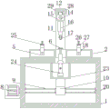
fig. 2 is a front sectional view of the present invention;
fig. 3 is a side sectional view of the present invention.
Wherein: 1. a machine platform; 2. a detection table; 3. turning a handle; 4. a double-ended screw; 5. a support block; 6. a pressure sensor; 7. an alarm; 8. a first motor; 9. a first screw; 10. moving the plate; 11. a support plate; 12. a top plate; 13. a second motor; 14. a second screw; 15. a thread block; 16. a hydraulic cylinder; 17. a pressure head; 18. a limiting groove; 19. a chute; 20. a limiting rod; 21. a pulley; 22. a slide rail; 23. a case; 24. a pneumatic cylinder; 25. rotating the plate; 26. locking the bolt; 27. a non-slip mat; 28. a limiting block; 29. and a limit rail.
Detailed Description
In order to deepen the understanding of the present invention, the following embodiments will be combined to make the present invention do further details, and the present embodiment is only used for explaining the present invention, and does not constitute the limitation of the protection scope of the present invention.
According to fig. 1, 2 and 3, the embodiment provides a hardness detection device for a high-hardness wear-resistant floor, which comprises a machine table 1, wherein a detection table 2 is fixed on the machine table 1, double-threaded screws 4 driven by rotating handles 3 are symmetrically arranged in the detection table 2 in a front-back manner, supporting blocks 5 are symmetrically sleeved on two sides of each double-threaded screw 4 through threads in opposite directions, the double-threaded screws 4 are driven by the rotating handles 3 to rotate, so that the supporting blocks 5 on the double-threaded screws 4 reversely displace along the double-threaded screws 4, a pressure sensor 6 is arranged in the detection table 2, an alarm 7 electrically connected with the pressure sensor 6 is arranged on the outer side of the detection table 2, the pressure sensor 6 is connected with a PLC control system of the device and used for driving the alarm 7 to give an alarm, a first screw 9 driven by a first motor 8 is arranged in the machine table 1, and a movable plate 10 is sleeved on the, drive first screw 9 through first motor 8 and rotate to make movable plate 10 along longitudinal displacement around first screw 9, the both sides symmetry of movable plate 10 is fixed with backup pad 11 that runs through board 1, the top of backup pad 11 is fixed with roof 12, be equipped with through second motor 13 driven second screw 14 between the backup pad 11, screw thread cover has the screw block 15 with roof 12 sliding connection on the second screw 14, the bottom of screw block 15 is connected with pressure head 17 through pneumatic cylinder 16, drives second screw 14 through second motor 13 and rotates, thereby makes screw block 15 on the second screw 14 drive pressure head 17 and controls lateral displacement.
The supporting block 5 is connected with the detection table 2 in a sliding mode, the detection table 2 is symmetrically provided with limiting grooves 18 matched with the supporting block 5, the supporting block 5 is enabled to be more stable in the moving process, the supporting plate 11 is connected with the machine table 1 in a sliding mode, the machine table 1 is symmetrically provided with sliding grooves 19 matched with the supporting plate 11, and the supporting plate (11) is enabled to be more stable in the moving process.
Limiting rods 20 in sliding connection with the moving plate 10 are symmetrically arranged on two sides of the first screw 9, and two ends of each limiting rod 20 are fixed on the front inner wall and the rear inner wall of the machine table 1 respectively, so that the moving plate 10 is more stable in the moving process.
Pulleys 21 are symmetrically installed at two ends of the supporting plate 11, a sliding rail 22 matched with the pulleys 21 is arranged on the machine table 1, and the pulleys 21 are slidably connected in the sliding rail 22, so that the supporting plate 11 is more efficient and convenient to move.
Detect the central point of platform 2 and board 1 and put the through-hole of seting up mutual intercommunication respectively, the top of board 1 inside is equipped with the machine box 23 that is located the through-hole position, be equipped with pneumatic cylinder 24 in the machine box 23, the bottom with pressure sensor 6 is connected on the top of pneumatic cylinder 24, adjusts pressure sensor 6's height through pneumatic cylinder 24 to be applicable to the detection that different hardness required.
The top of supporting shoe 5 articulates there is commentaries on classics board 25, install locking bolt 26 through the screw thread on the commentaries on classics board 25, the bottom mounting of locking bolt 26 has slipmat 27, is convenient for fix the floor that awaits measuring.
The top end of the thread block 15 is fixed with a limiting block 28, and the bottom end of the top plate 12 is provided with a limiting rail 29 matched with the limiting block 28, so that the thread block 15 is more stable in the moving process.
When the hardness of a high-hardness wear-resistant floor needs to be detected, firstly, the double-headed screw rod 4 is driven to rotate by the rotating handle 3, the supporting block 5 is adjusted to a proper position according to the specification and size of the floor to be detected, then, the floor to be detected is placed on the supporting block 5, the supporting block 5 is driven by the rotating handle 3 to clamp and fix the floor, then, the rotating plate 25 is rotated, the floor is tightly pressed and fixed by screwing the locking bolt 26, so that the bottom plate is kept stable in the detection process, then, the pressure sensor 6 is adjusted to a proper height below the floor by the pneumatic cylinder 24, then, the driving head 17 is driven by the hydraulic cylinder 16 to descend to a proper height and press the floor, when the floor is bent under pressure and touches the pressure sensor 6, the pressure sensor 6 drives the alarm 7 to alarm by the PLC control system of the device, the, when the floor receives pressure but does not touch pressure sensor 6 then the explanation floor is qualified, wait to detect and take off the floor after finishing and carry out the detection on next floor, if need detect the different positions on floor in the testing process, then drive pressure head 17 respectively through first motor 8 and second motor 13 and do longitudinal displacement and lateral displacement to adjust pressure head 17 according to actual detection position, and then detect the degree of accuracy that guarantees the testing result through the hardness of different positions.
The hardness detection device for the high-hardness wear-resistant floor comprises a machine table 1, wherein a hydraulic cylinder 16 drives a pressure head 17 to press the floor on a detection table 2, a pressure sensor 6 in the detection table 2 senses whether the floor is bent or not, so that the hardness of the floor is qualified, a rotating handle 3 drives a double-end screw rod 4 to rotate, so that a supporting block 5 on the double-end screw rod 4 is transversely displaced, the supporting block 5 is properly adjusted according to the specification of the floor to be detected, the floor is supported and clamped and fixed, the device can be suitable for the hardness detection of floors with different specifications and sizes, the practicability is high, a first motor 8 drives a first screw rod 9 to rotate, so that a supporting plate 11 on the first screw rod 9 drives a pressure head 17 to longitudinally displace forwards and backwards, a second motor 13 drives a second screw rod 14 to rotate, and a thread block 15 drives the pressure head 17 to transversely displace leftwards and rightwards, and then make the device be convenient for adjust the pressure head position, make the device can carry out hardness detection to the different positions on floor, convenient to use has guaranteed the degree of accuracy of hardness testing result simultaneously.
The foregoing illustrates and describes the principles, general features, and advantages of the present invention. It will be understood by those skilled in the art that the present invention is not limited to the above embodiments, and that the foregoing embodiments and descriptions are provided only to illustrate the principles of the present invention without departing from the spirit and scope of the present invention. The scope of the invention is defined by the appended claims and equivalents thereof.
Claims (7)
1. The utility model provides a hardness detection device on wear-resisting floor of high rigidity, includes board (1), its characterized in that: the detection device is characterized in that a detection table (2) is fixed on the machine table (1), double-threaded screws (4) driven by a rotating handle (3) are symmetrically arranged in the detection table (2) in a front-back mode, supporting blocks (5) are symmetrically sleeved on two sides of each double-threaded screw (4) through threads in opposite directions, pressure sensors (6) are arranged in the detection table (2), an alarm (7) electrically connected with the pressure sensors (6) is arranged on the outer side of the detection table (2), first screws (9) driven by a first motor (8) are arranged in the machine table (1), a movable plate (10) is sleeved on the first screws (9) in a threaded mode, supporting plates (11) penetrating through the machine table (1) are symmetrically fixed on two sides of the movable plate (10), a top plate (12) is fixed on the top ends of the supporting plates (11), and second screws (14) driven by a second motor (13) are arranged between the supporting plates (11), the second screw rod (14) is sleeved with a thread block (15) in sliding connection with the top plate (12) in a threaded manner, and the bottom end of the thread block (15) is connected with a pressure head (17) through a hydraulic cylinder (16).
2. The apparatus for detecting hardness of a high-hardness abrasion-resistant floor according to claim 1, wherein: the supporting block (5) is connected with the detection table (2) in a sliding mode, limiting grooves (18) matched with the supporting block (5) are symmetrically formed in the detection table (2), the supporting plate (11) is connected with the machine table (1) in a sliding mode, and sliding grooves (19) matched with the supporting plate (11) are symmetrically formed in the machine table (1).
3. The apparatus for detecting hardness of a high-hardness abrasion-resistant floor according to claim 1, wherein: first screw rod (9) bilateral symmetry is equipped with gag lever post (20) with movable plate (10) sliding connection, the both ends of gag lever post (20) are fixed in on the front and back inner wall of board (1) respectively.
4. The apparatus for detecting hardness of a high-hardness abrasion-resistant floor according to claim 1, wherein: pulleys (21) are symmetrically installed at two ends of the supporting plate (11), a sliding rail (22) matched with the pulleys (21) is arranged on the machine table (1), and the pulleys (21) are connected in the sliding rail (22) in a sliding mode.
5. The apparatus for detecting hardness of a high-hardness abrasion-resistant floor according to claim 1, wherein: detect the central point of platform (2) and board (1) and put the through-hole of seting up mutual intercommunication respectively, the inside top of board (1) is equipped with machine box (23) that are located the through-hole position, be equipped with pneumatic cylinder (24) in machine box (23), the bottom of connecting with pressure sensor (6) on the top of pneumatic cylinder (24).
6. The apparatus for detecting hardness of a high-hardness abrasion-resistant floor according to claim 1, wherein: the top of supporting shoe (5) articulates there is commentaries on classics board (25), change and install locking bolt (26) through the screw thread on board (25), the bottom mounting of locking bolt (26) has slipmat (27).
7. The apparatus for detecting hardness of a high-hardness abrasion-resistant floor according to claim 1, wherein: the top end of the thread block (15) is fixed with a limiting block (28), and the bottom end of the top plate (12) is provided with a limiting rail (29) matched with the limiting block (28).
Priority Applications (1)
| Application Number | Priority Date | Filing Date | Title |
|---|---|---|---|
| CN202021147999.XU CN212340893U (en) | 2020-06-19 | 2020-06-19 | Hardness detection device for high-hardness wear-resistant floor |
Applications Claiming Priority (1)
| Application Number | Priority Date | Filing Date | Title |
|---|---|---|---|
| CN202021147999.XU CN212340893U (en) | 2020-06-19 | 2020-06-19 | Hardness detection device for high-hardness wear-resistant floor |
Publications (1)
| Publication Number | Publication Date |
|---|---|
| CN212340893U true CN212340893U (en) | 2021-01-12 |
Family
ID=74077994
Family Applications (1)
| Application Number | Title | Priority Date | Filing Date |
|---|---|---|---|
| CN202021147999.XU Expired - Fee Related CN212340893U (en) | 2020-06-19 | 2020-06-19 | Hardness detection device for high-hardness wear-resistant floor |
Country Status (1)
| Country | Link |
|---|---|
| CN (1) | CN212340893U (en) |
Cited By (3)
| Publication number | Priority date | Publication date | Assignee | Title |
|---|---|---|---|---|
| CN114646556A (en) * | 2022-05-19 | 2022-06-21 | 常州市超创机械设备有限公司 | Motor car reservoir end wall hardness detection device |
| CN116793844A (en) * | 2023-06-29 | 2023-09-22 | 广州市盛通建设工程质量检测有限公司 | Building material strength detection equipment and detection method |
| CN117110079A (en) * | 2023-10-24 | 2023-11-24 | 宝鸡海华金属复合材料有限公司 | Composite board detection device |
-
2020
- 2020-06-19 CN CN202021147999.XU patent/CN212340893U/en not_active Expired - Fee Related
Cited By (5)
| Publication number | Priority date | Publication date | Assignee | Title |
|---|---|---|---|---|
| CN114646556A (en) * | 2022-05-19 | 2022-06-21 | 常州市超创机械设备有限公司 | Motor car reservoir end wall hardness detection device |
| CN116793844A (en) * | 2023-06-29 | 2023-09-22 | 广州市盛通建设工程质量检测有限公司 | Building material strength detection equipment and detection method |
| CN116793844B (en) * | 2023-06-29 | 2024-01-26 | 广州市盛通建设工程质量检测有限公司 | Building material strength detection equipment and detection method |
| CN117110079A (en) * | 2023-10-24 | 2023-11-24 | 宝鸡海华金属复合材料有限公司 | Composite board detection device |
| CN117110079B (en) * | 2023-10-24 | 2023-12-15 | 宝鸡海华金属复合材料有限公司 | Composite board detection device |
Similar Documents
| Publication | Publication Date | Title |
|---|---|---|
| CN212340893U (en) | Hardness detection device for high-hardness wear-resistant floor | |
| CN207300778U (en) | A kind of abrasion wear test machine for being used to test thin slice | |
| CN211346672U (en) | A high-efficient check out test set of mainframe box roughness for computer technology development | |
| CN210401191U (en) | Part detection device based on photoelectric integration technology | |
| CN217132538U (en) | Torque testing machine convenient to centre gripping | |
| CN206088337U (en) | Sucker clamp | |
| CN210773817U (en) | Nut internal thread reinspection and trial assembly device | |
| CN211346760U (en) | Guide rail plane smoothness detection device | |
| CN205733912U (en) | Simple scale location formula steel plate fixture table top device | |
| CN209999158U (en) | kinds of building detection tool storage device | |
| CN220751878U (en) | Hardness detection device for material science | |
| CN216410042U (en) | Arc-shaped furniture board surface flatness detection equipment | |
| CN218470577U (en) | High-precision metal piece surface scratch visual detection device | |
| CN220637225U (en) | Grinding device for steel processing | |
| CN206627043U (en) | A kind of flywheel end face jitter detection apparatus | |
| CN219945279U (en) | Board clamping tool for numerical control machining | |
| CN212390927U (en) | Detection positioning device of automobile part checking fixture | |
| CN220161624U (en) | Positioning and aligning device for manufacturing steel structure | |
| CN216707210U (en) | A medium plate turning device for medium plate outward appearance flaw detects machine | |
| CN213105670U (en) | Medical instrument frame cover plate machining tool | |
| CN217980198U (en) | Instrument measuring microscope convenient to adjust | |
| CN219641367U (en) | Intelligent gauge length appearance is detected to reinforcing bar | |
| CN214096930U (en) | A intensity detection device for timber production | |
| CN217765812U (en) | Material clamping device for detection | |
| CN216992166U (en) | Cutting device is used in architectural decoration curtain production |
Legal Events
| Date | Code | Title | Description |
|---|---|---|---|
| GR01 | Patent grant | ||
| GR01 | Patent grant | ||
| CF01 | Termination of patent right due to non-payment of annual fee | ||
| CF01 | Termination of patent right due to non-payment of annual fee |
Granted publication date: 20210112 Termination date: 20210619 |