CN212338414U - Corridor gallows convenient to installation - Google Patents
Corridor gallows convenient to installation Download PDFInfo
- Publication number
- CN212338414U CN212338414U CN202020247201.2U CN202020247201U CN212338414U CN 212338414 U CN212338414 U CN 212338414U CN 202020247201 U CN202020247201 U CN 202020247201U CN 212338414 U CN212338414 U CN 212338414U
- Authority
- CN
- China
- Prior art keywords
- jib
- rail
- fixed
- link
- spring
- Prior art date
- Legal status (The legal status is an assumption and is not a legal conclusion. Google has not performed a legal analysis and makes no representation as to the accuracy of the status listed.)
- Expired - Fee Related
Links
Images

Abstract
The utility model relates to a gallows technical field, specific corridor gallows convenient to installation that says so, including fixed plate and jib, the lower surface center department symmetrical weld of fixed plate is fixed with and supports the rail, two support interval distribution and form logical groove between the rail, it is equipped with the jib to lead to the inslot, the bottom of jib is from last to the movable sleeve in proper order down being equipped with link and spring, the bottom welded fastening of link is on last solid fixed ring, gu fixed ring's both ends are fixed with solid fixed ring down through connecting bolt respectively. The utility model discloses a split type design, the convenience is installed the dismantlement to fixed plate and jib, conveniently carries out fast assembly with jib and fixed plate through supporting the rail, need not lift for a long time, simple to operate, and labour saving in operation, rotatory adjusting nut can promote the spring and then promote the link, conveniently adjusts the pipe-line erection height, utilizes the spring to cushion the shock attenuation to the link, prevents that the pipeline from receiving bigger loss.
Description
Technical Field
The utility model belongs to the technical field of a gallows device, concretely relates to a gallows in corridor convenient to installation.
Background
A support and hanger is a common supporting structure in pipeline construction. At present, when the support and hanger are installed, the sizes of all parts are prepared and processed by adopting a prefabricating method. In the in-service use process, because the precision difference when installing, there is certain difference between the design supporting height of a gallows and the actual mounting height of pipeline, can make a gallows can't accurate cooperate with the pipeline, because the inconvenient adjustment supporting height of a current gallows, cause that partial gallows can't provide effectual support, influence the stability that the pipeline supported. In addition, if the pipe is impacted to a greater extent, the existing support and hanger cannot perform buffer protection, so that the pipe is greatly damaged, and therefore, the existing support and hanger needs to be improved.
SUMMERY OF THE UTILITY MODEL
An object of the utility model is to provide a gallows is propped up in corridor convenient to installation to solve the problem that proposes among the above-mentioned background art.
In order to achieve the above object, the utility model provides a following technical scheme: the utility model provides a corridor gallows convenient to installation, includes fixed plate and jib, the both ends of fixed plate are fixed at the building top through expansion bolts respectively, the lower surface center department symmetrical welded fastening of fixed plate has a support rail, two support interval distribution and form logical groove between the rail, it is equipped with the jib to lead to the inslot, the top welded fastening of jib has the layer board of overlap joint on supporting the rail, the bottom of jib is from last to having link and spring to lower movable sleeve in proper order, the bottom of jib still has adjusting nut through threaded connection, the bottom welded fastening of link is on last solid fixed ring, solid fixed ring's both ends are fixed with solid fixed ring down through connecting bolt respectively.
As a further optimization of the technical scheme, a limiting groove is formed in the bottom of the supporting rail, the supporting plate is arranged in the limiting groove, and the length of the supporting plate is the same as the width of the inner space of the two supporting rails.
As a further optimization of the technical scheme, the upper end of the hanging rod is further connected with a locking nut through threads, and the locking nut is tightly abutted to the bottom of the supporting rail.
As a further optimization of the technical scheme, the top end of the spring is tightly abutted to the top of the connecting frame, the bottom end of the spring is tightly abutted to the base plate, and the base plate is sleeved on the suspension rod and abutted to the bottom of the adjusting nut.
As a further optimization of the technical scheme, a layer of rubber bushing is fixed on the inner side walls of the upper fixing ring and the lower fixing ring.
The utility model discloses a technological effect and advantage:
the utility model discloses a split type design, the convenience is installed the dismantlement to fixed plate and jib, conveniently carry out fast assembly with jib and fixed plate through supporting the rail, need not lift for a long time, high durability and convenient installation, and is laborsaving in operation, rotatory adjusting nut can promote the spring and then promote the link, thereby adjust the height of solid fixed ring and lower fixing ring, the convenience is adjusted the piping erection height, utilize the spring, can cushion the shock attenuation to the link, make the pipeline receive by a relatively large margin after offeing, the link can be along jib up-and-down motion, utilize the spring to cushion protection, prevent that the pipeline from receiving more loss.
Drawings
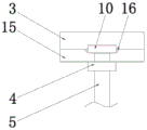
Fig. 1 is a schematic structural view of the present invention;
fig. 2 is a schematic view of the inner side structure of the support rail of the present invention.
In the figure: 1. an expansion bolt; 2. a fixing plate; 3. a support rail; 4. locking the nut; 5. a boom; 6. a connecting frame; 7. adjusting the nut; 8. an upper fixing ring; 9. a lower fixing ring; 10. a support plate; 11. a spring; 12. a base plate; 13. a connecting bolt; 14. a rubber bushing; 15. a through groove; 16. a limiting groove.
Detailed Description
The technical solutions in the embodiments of the present invention will be described clearly and completely below with reference to the embodiments of the present invention, and it is obvious that the described embodiments are only some embodiments of the present invention, not all embodiments. Based on the embodiments in the present invention, all other embodiments obtained by a person skilled in the art without creative work belong to the protection scope of the present invention.
As shown in figures 1-2, the corridor support and hanger convenient to install comprises a fixing plate 2 and a hanger rod 5, wherein two ends of the fixing plate 2 are respectively fixed at the top of a building through expansion bolts 1, the fixing plate 2 is pre-installed through the expansion bolts 1, and a split connection mode is adopted with the hanger rod 5, so that the installation is convenient.
The center of the lower surface of the fixed plate 2 is symmetrically welded and fixed with support rails 3, through grooves 15 are formed between the two support rails 3 at intervals, suspenders 5 are arranged in the through grooves 15, support plates 10 lapped on the support rails 3 are welded and fixed at the tops of the suspenders 5, the support plates 10 are limited between the two support rails 3 through the through grooves 15, the suspenders 5 can slide into the support rails 3 from two ends of the through grooves 15, the installation is convenient, long-time lifting is not needed, the operation is labor-saving, the support plates 10 bear the weight of the suspenders 5, limiting grooves 16 are arranged at the inner bottom of the support rails 3, the support plates 10 are arranged in the limiting grooves 16, the length of the support plates 10 is the same as the width of the inner space of the two support rails 3, the limiting grooves 16 are utilized for limiting and positioning the support plates 10 to prevent the suspenders 5 from shifting, and locking nuts 4 are further connected to the, the locking nut 4 is tightly propped against the bottom of the support rail 3, after the locking nut 4 is screwed, the supporting plate 10 can be reversely pulled and fixed in the limiting groove 16, the suspender 5 can be fixed,
the bottom of jib 5 is from last to lower in proper order the movable sleeve be equipped with link 6 and spring 11, there is adjusting nut 7 bottom of jib 5 still through threaded connection, the top and the 6 tops of link of spring 11 support tightly, the bottom and the backing plate 12 of spring 11 support tightly, backing plate 12 cover is established on jib 5 and is offset with adjusting nut 7 bottom, and rotatory adjusting nut 7 can promote spring 11, and then promotes link 6 to the height of solid fixed ring 8 and lower solid fixed ring 9 in the adjustment, conveniently adjust the mounting height, utilize spring 11, can cushion the shock attenuation to link 6, make the pipeline receive great range's clash the back, link 6 can be along jib 5 up-and-down motion, utilize spring 11 to cushion protection, prevent that the pipeline from receiving more loss.
The bottom welded fastening of link 6 is on last solid fixed ring 8, the both ends of last solid fixed ring 8 are fixed with lower fixing ring 9 through connecting bolt 13 respectively, all be fixed with one deck rubber bush 14 on the inside wall of last solid fixed ring 8 and lower fixing ring 9, utilize rubber bush 14, protect the pipeline outer wall, avoid pipeline surface protection lacquer layer wearing and tearing.
Specifically, during the use, at first utilize expansion bolts 1 to fix fixed plate 2 on the ceiling, later with layer board 10 of jib 5 upper end slide in limiting groove 16 from logical groove 15 between the support rail 3, treat layer board 10 and accomplish the location back, lock nut 4 screws, anti-draw tight in limiting groove 16 with layer board 10, accomplish fixedly to jib 5, later establish link 6 cover in jib 5 bottom, and fix lower fixing ring 9 and upper fixing ring 8 through connecting bolt 13, surround at the pipeline outside, rotatory adjusting nut 7, it compresses to support tight spring 11, thereby promote link 6, make link 6 keep dynamic stability. When the pipe is hit by a larger magnitude, the link 6 can move up and down along the boom 5, so that the shock is buffered by the spring 11, preventing the pipe from being more lost.
Finally, it should be noted that: although the present invention has been described in detail with reference to the foregoing embodiments, it will be apparent to those skilled in the art that modifications and variations can be made in the embodiments or in part of the technical features of the embodiments without departing from the spirit and the scope of the invention.
Claims (5)
1. A corridor gallows convenient to installation, includes fixed plate (2) and jib (5), its characterized in that: the both ends of fixed plate (2) are fixed at the building top through expansion bolts (1) respectively, the lower surface center department symmetry welded fastening of fixed plate (2) has support rail (3), two support interval distribution between rail (3) and form logical groove (15), be equipped with jib (5) in leading to groove (15), the top welded fastening of jib (5) has layer board (10) of overlap joint on supporting rail (3), the bottom of jib (5) is from last to lower movable sleeve in proper order to be equipped with link (6) and spring (11), the bottom of jib (5) still has adjusting nut (7) through threaded connection, the bottom welded fastening of link (6) is on last solid fixed ring (8), the both ends of going up solid fixed ring (8) are fixed with down solid fixed ring (9) through connecting bolt (13) respectively.
2. A corridor support hanger as claimed in claim 1, which is easy to install and in which: the bottom in the support rail (3) is provided with a limiting groove (16), the supporting plate (10) is arranged in the limiting groove (16), and the length of the supporting plate (10) is the same as the width of the inner space of the two support rails (3).
3. A corridor support hanger as claimed in claim 1, which is easy to install and in which: the upper end of the suspender (5) is also connected with a locking nut (4) through threads, and the locking nut (4) is tightly propped against the bottom of the supporting rail (3).
4. A corridor support hanger as claimed in claim 1, which is easy to install and in which: the top end of the spring (11) is tightly abutted to the top of the connecting frame (6), the bottom end of the spring (11) is tightly abutted to the backing plate (12), and the backing plate (12) is sleeved on the suspension rod (5) and abutted to the bottom of the adjusting nut (7).
5. A corridor support hanger as claimed in claim 1, which is easy to install and in which: and a layer of rubber bushing (14) is fixed on the inner side walls of the upper fixing ring (8) and the lower fixing ring (9).
Priority Applications (1)
| Application Number | Priority Date | Filing Date | Title |
|---|---|---|---|
| CN202020247201.2U CN212338414U (en) | 2020-03-04 | 2020-03-04 | Corridor gallows convenient to installation |
Applications Claiming Priority (1)
| Application Number | Priority Date | Filing Date | Title |
|---|---|---|---|
| CN202020247201.2U CN212338414U (en) | 2020-03-04 | 2020-03-04 | Corridor gallows convenient to installation |
Publications (1)
| Publication Number | Publication Date |
|---|---|
| CN212338414U true CN212338414U (en) | 2021-01-12 |
Family
ID=74084806
Family Applications (1)
| Application Number | Title | Priority Date | Filing Date |
|---|---|---|---|
| CN202020247201.2U Expired - Fee Related CN212338414U (en) | 2020-03-04 | 2020-03-04 | Corridor gallows convenient to installation |
Country Status (1)
| Country | Link |
|---|---|
| CN (1) | CN212338414U (en) |
Cited By (2)
| Publication number | Priority date | Publication date | Assignee | Title |
|---|---|---|---|---|
| CN113188022A (en) * | 2021-05-18 | 2021-07-30 | 湖南喜得发展工贸有限公司 | Be applied to screw rod of a building gallows fastener and connect |
| CN115621933A (en) * | 2022-09-13 | 2023-01-17 | 中建八局第二建设有限公司 | Connecting assembly and electromechanical mounting support and hanger for building |
-
2020
- 2020-03-04 CN CN202020247201.2U patent/CN212338414U/en not_active Expired - Fee Related
Cited By (2)
| Publication number | Priority date | Publication date | Assignee | Title |
|---|---|---|---|---|
| CN113188022A (en) * | 2021-05-18 | 2021-07-30 | 湖南喜得发展工贸有限公司 | Be applied to screw rod of a building gallows fastener and connect |
| CN115621933A (en) * | 2022-09-13 | 2023-01-17 | 中建八局第二建设有限公司 | Connecting assembly and electromechanical mounting support and hanger for building |
Similar Documents
| Publication | Publication Date | Title |
|---|---|---|
| CN212338414U (en) | Corridor gallows convenient to installation | |
| CN205295960U (en) | Bridge construction support bracket | |
| CN216976012U (en) | Construction water supply and drainage pipe connection fixing construction device | |
| CN208430517U (en) | Bracing members hanging plate for subway foundation pit construction | |
| CN213951912U (en) | Bridge anti-seismic support hanger | |
| CN214061705U (en) | Civil engineering foundation structure subsides self-adaptation telescopic connection device | |
| CN212536958U (en) | Supplementary installation frock of a gallows combats and shakes | |
| CN204956633U (en) | Horizontal beam supports of suspension | |
| CN210151984U (en) | Be used for building antidetonation a gallows structure | |
| CN209892871U (en) | Pipeline hanger device | |
| CN209115905U (en) | A kind of foundation bolt for vibratory equipment | |
| CN220555929U (en) | Tensioning device suitable for suspension type double-steel inner cylinder chimney | |
| CN204895100U (en) | Engine mounting assembly | |
| CN216867741U (en) | Flexible ceiling support fixing device of PSP steel-plastic composite pipe | |
| CN215802523U (en) | Glass curtain wall connecting structure | |
| CN214744116U (en) | A gallows of combatting earthquake that suitability is strong | |
| CN210739573U (en) | Slidable formula pipeline gallows | |
| CN218931544U (en) | Large-angle luffing mechanism for portal crane | |
| CN211175632U (en) | Air pipe supporting device | |
| CN220016365U (en) | Hoisting support of air pipe | |
| CN219117938U (en) | Abutment support structure for hydraulic engineering | |
| CN212859205U (en) | High-stability clamping device for metal casting | |
| CN208123627U (en) | A kind of water pipeline support connection structure | |
| CN108397897A (en) | Adjustable climate control water rack mounting structure and application method | |
| CN210600448U (en) | Position-adjustable support hanger |
Legal Events
| Date | Code | Title | Description |
|---|---|---|---|
| GR01 | Patent grant | ||
| GR01 | Patent grant | ||
| CF01 | Termination of patent right due to non-payment of annual fee | ||
| CF01 | Termination of patent right due to non-payment of annual fee |
Granted publication date: 20210112 |