CN212334081U - Cloth rewinder that dedicated automation of all cotton flannel processing removed dust - Google Patents
Cloth rewinder that dedicated automation of all cotton flannel processing removed dust Download PDFInfo
- Publication number
- CN212334081U CN212334081U CN202020726256.1U CN202020726256U CN212334081U CN 212334081 U CN212334081 U CN 212334081U CN 202020726256 U CN202020726256 U CN 202020726256U CN 212334081 U CN212334081 U CN 212334081U
- Authority
- CN
- China
- Prior art keywords
- dust
- cloth rolling
- fixedly connected
- baffle
- bearing platform
- Prior art date
- Legal status (The legal status is an assumption and is not a legal conclusion. Google has not performed a legal analysis and makes no representation as to the accuracy of the status listed.)
- Active
Links
Images


Abstract
The utility model discloses a special automatic dust-removing cloth rolling machine for processing all-cotton flannelette, which comprises a bearing platform, wherein the left and right sides of the rear side of the top of the bearing platform are symmetrically and fixedly connected with baffle covers, one side of the inner chambers of the two baffle covers, which are close to each other, is provided with a cylinder, the outer walls of the two cylinder columns are provided with dust-removing fiber cylinder brushes, the upper and lower ends of the two cylinder columns are fixedly connected with a first rotating shaft, the bottom of the bearing platform is provided with a support plate, the top of the support plate is provided with a driving motor and a dust collector, one end of the two first rotating shafts at the lower end, which penetrates through the bottom of the bearing platform, is fixedly connected with a gear, the right input end of the dust collector is communicated with a Y-shaped dust-collecting hose, the left side of the top of the bearing platform is fixedly connected with a vertical plate, the left side wall of the vertical plate is provided with, the processing efficiency of flannelette is improved, reduces operation personnel's intensity of labour.
Description
Technical Field
The utility model relates to an all cotton flannel processing technology field, concretely relates to dedicated automatic cloth rewinder that removes dust of all cotton flannel processing.
Background
The all cotton refers to clothes or articles containing 100% cotton, generally plain cloth, poplin, twill cloth, working cloth, etc., and different from general cloth, it has the advantages of deodorization, ventilation and comfort, etc., the lint refers to cotton fabric whose surface is presented with rich fluff after napping, and the needle holes on the surface of the cloth are used for napping, so that more fluff is produced, the stereoscopic impression is strong, the glossiness is high, and the cotton fabric is soft and thick to touch.
At present, in the production and processing process of all-cotton flannelette, due to the influence of external factors, some dust can be attached to the flannelette, and the flannelette is generally subjected to dust shaking and removing by manual operation of an operator, so that the processing efficiency of the flannelette is reduced to a great extent, the labor intensity of the operator is increased, and therefore, the cloth rolling machine special for automatically removing the dust in the all-cotton flannelette processing is provided.
SUMMERY OF THE UTILITY MODEL
An object of the utility model is to overcome the above-mentioned problem that exists among the prior art, provide a cloth rewinder that dedicated automation of all cotton flannel processing removed dust, be convenient for get rid of adnexed dust on the flannel, improve the machining efficiency of flannel, reduce operation personnel's intensity of labour.
In order to realize the technical purpose, the technical effect is achieved, the utility model discloses a realize through following technical scheme:
a cloth rolling machine for automatically removing dust specially used for processing all-cotton flannelette comprises a bearing platform, wherein baffle covers are symmetrically and fixedly connected with the left side and the right side of the rear side of the top of the bearing platform, tube columns are arranged on the sides, close to each other, of the inner cavities of two groups of the baffle covers, dust-removing fiber tube brushes are arranged on the outer walls of the two groups of the tube columns, first rotating shafts are fixedly connected with the upper ends and the lower ends of the two groups of the tube columns, the top of the first rotating shaft at the upper end is connected with the baffle covers in a switching mode, the first rotating shaft at the lower end is connected with the bearing platform in a switching mode, the bottom of the first rotating shaft at the lower end penetrates through the bottom of the bearing platform, a supporting plate is arranged at the bottom of the bearing platform, supporting leg columns are fixedly connected with the left end and the right end of the rear side wall of the supporting plate, the top power output end of the driving motor is connected with one end, penetrating through the bottom of the bearing table, of a first rotating shaft on the left side of the lower end, gears are fixedly connected to one ends, penetrating through the bottom of the bearing table, of two groups of first rotating shafts on the lower end, the two groups of gears are meshed with each other, and the right input end of the dust collector is communicated with a Y-shaped dust collection hose;
a vertical plate is fixedly connected to the left side of the top of the bearing table, a cylinder is arranged on the left side wall of the vertical plate, a cross bar plate is fixedly connected to the top power expansion end of the cylinder, the right end of the cross bar plate penetrates through the right side wall of the vertical plate, the horizontal strip plate is connected with the vertical plate in a sliding way, the right side of the vertical plate is provided with a cloth rolling roller which is positioned at the front side of the shield, the upper end and the lower end of the cloth rolling roller are symmetrically inserted with second rotating shafts, the top of the second rotating shaft at the upper end is connected with the horizontal strip plate in a switching way, the bottom of the second rotating shaft at the lower end is connected with the bearing platform in a switching way, the bottom of the second rotating shaft at the lower end penetrates through the bottom of the bearing table, two groups of second rotating shafts are fixedly connected with baffle discs, and two groups of baffle discs are respectively positioned at the upper side and the lower side of the cloth rolling roller, a cloth rolling motor is arranged at the front side of the bottom of the bearing platform, the top power output end of the cloth rolling motor is connected with one end of a second rotating shaft at the lower end, which penetrates through the bottom of the bearing table;
two sets of keep off the one end that the inner chamber rear side wall of cover was pressed close to each other and all seted up into dirt window, it is two sets of the one end symmetry that the front side of advancing dirt window kept away from each other is provided with and keeps off the class board, and keeps off the rear side wall of class board and keeps off cover looks rigid coupling, the upper surface rear side of plummer is opened and is equipped with and dodges the groove with Y shape dust absorption hose matched with, and dodges the inner chamber lower surface in groove and runs through the lower surface of plummer, the input of the left and right sides of Y shape dust absorption hose all communicates there is dust box cover, and the inner chamber of dust box cover corresponds through advancing dirt window and fender cover and.
Preferably, in the cloth rolling machine for automatically removing dust specially used for processing all-cotton flannelette, the dust removal fiber drum brush and the flow baffle are in clearance fit, so that interference and obstruction of the dust removal fiber drum brush by the flow baffle are avoided, and the rotation of the dust removal fiber drum brush is facilitated.
Preferably, in the cloth rolling machine for automatically removing dust specially used for processing all-cotton flannelette, the front end and the rear end of the bottom of the left side wall of the vertical plate are symmetrically and fixedly connected with the supporting rib plates, and the bottoms of the supporting rib plates are fixedly connected with the bearing platform, so that the vertical plate can be conveniently and stably fixed on the bearing platform.
Preferably, in the cloth rolling machine for automatically removing dust specially used for processing all-cotton flannelette, the top of the vertical plate is provided with a containing groove matched with the horizontal strip plate, the front side wall and the rear side wall of the inner cavity of the containing groove are symmetrically provided with guide grooves, and the front side wall and the rear side wall of the horizontal strip plate are symmetrically and fixedly connected with guide blocks matched with the guide grooves, so that the horizontal strip plate can be conveniently guided to move on the vertical plate.
Preferably, in the cloth rolling machine for automatically removing dust specially used for processing all-cotton flannelette, the joint between the guide block and the guide groove is smooth, so that friction is reduced, and the guide block can conveniently slide in the guide groove.
Preferably, in the above-mentioned cloth rewinder that is arranged in dedicated automation of cotton flannel processing and removes dust, spacing shrinkage pool has been seted up to the bottom left and right sides symmetry of batching cylinder, and the lower extreme keep off the top left and right sides symmetry of dish and be provided with spacing shrinkage pool matched with spacing arch, be convenient for to the spacing of batching cylinder between two sets of fender dishes.
Preferably, in the cloth rolling machine for automatically removing dust specially used for processing all-cotton flannelette, the bottoms of the four groups of supporting leg columns are respectively provided with an anti-slip pad, so that the supporting leg columns can be prevented from slipping on the ground conveniently.
Compared with the prior art, the beneficial effects of the utility model are as follows:
the utility model has the advantages of reasonable design, on one hand, to the lint before rolling, through the meshing cooperation between two sets of gears, under the driving action of driving motor, make two sets of dust removal fibre section of thick bamboo brushes to the two-sided brush of lint, through the cooperation of dust catcher, Y-shaped dust absorption hose, draw dirt box cover, dust inlet window and baffling board, absorb the dust that the brush got off, thereby be convenient for get rid of the dust that adheres to on the lint, improve the machining efficiency of lint, reduce operation personnel's intensity of labour; on the other hand drives the batching cylinder through the batching motor and rolls the flannelette of getting rid of the dust, through the flexible regulating action of cylinder, is convenient for to the installation and the dismantlement of batching cylinder between two sets of fender dishes.
Of course, it is not necessary for any particular product to achieve all of the above-described advantages at the same time.
Drawings
In order to more clearly illustrate the technical solutions of the embodiments of the present invention, the drawings used in the description of the embodiments will be briefly introduced below, and it is obvious that the drawings in the following description are only some embodiments of the present invention, and it is obvious for those skilled in the art that other drawings can be obtained according to these drawings without creative efforts.
Fig. 1 is a schematic view of a usage state structure of the present invention;
FIG. 2 is a second schematic view of the structure of the utility model in use;
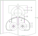
fig. 3 is a schematic structural view of the top view of fig. 1 in a partial use state according to the present invention;
FIG. 4 is a schematic view showing a usage state of the Y-shaped dust suction hose of the present invention;
in the drawings, the components represented by the respective reference numerals are listed below:
1-bearing platform, 2-baffle cover, 3-cylinder column, 4-dust-removing fiber cylinder brush, 5-first rotating shaft, 6-supporting plate, 7-supporting leg column, 8-driving motor, 9-dust collector, 10-gear, 11-vertical plate, 12-cylinder, 13-cross plate, 14-cloth rolling roller, 15-second rotating shaft, 16-baffle disc, 17-cloth rolling motor, 18-Y-shaped dust collecting hose, 19-dust inlet window, 20-baffle plate, 21-avoiding groove and 22-dust guiding box cover.
Detailed Description
The technical solutions in the embodiments of the present invention will be described clearly and completely with reference to the accompanying drawings in the embodiments of the present invention, and it is obvious that the described embodiments are only some embodiments of the present invention, not all embodiments. Based on the embodiments of the present invention, all other embodiments obtained by a person of ordinary skill in the art without creative efforts belong to the protection scope of the present invention.
Referring to fig. 1-4, a cloth rolling machine for automatically removing dust specially used for processing cotton flannelette comprises a bearing platform 1, wherein baffle covers 2 are symmetrically and fixedly connected to the left and right sides of the rear side of the top of the bearing platform 1, the adjacent sides of the inner cavities of the two groups of baffle covers 2 are respectively provided with a cylinder 3, the outer walls of the two groups of cylinder 3 are respectively provided with a dust-removing fiber cylinder brush 4, the upper and lower ends of the two groups of cylinder 3 are respectively fixedly connected with a first rotating shaft 5, the top of the first rotating shaft 5 at the upper end is connected with the baffle covers 2 in a switching manner, the first rotating shaft 5 at the lower end is connected with the bearing platform 1 in a switching manner, the bottom of the first rotating shaft 5 at the lower end penetrates through the bottom of the bearing platform 1, the bottom of the bearing platform 1 is provided with a supporting plate 6, the left and right ends of the front side wall and the left and right ends of the rear side wall of the supporting plate 6 are respectively, the anti-skidding support leg column 7 on the ground is facilitated, the top of the support plate 6 is provided with a driving motor 8 and a dust collector 9, the driving motor 8 is positioned at the front side of the dust collector 9, the top power output end of the driving motor 8 is connected with one end, penetrating through the bottom of the bearing platform 1, of the first rotating shaft 5 at the left side of the lower end, gears 10 are fixedly connected to one end, penetrating through the bottom of the bearing platform 1, of the two groups of first rotating shafts 5 at the lower end, the two groups of gears 10 are meshed with each other, the right side input end of the dust collector 9 is communicated with a Y-shaped dust collection hose 18, the top left side of the bearing platform 1 is fixedly connected with a vertical plate 11, the front end and the rear end of the bottom of the left side wall of the vertical plate 11 are symmetrically fixedly connected with support rib plates, the bottoms of the support rib plates are fixedly connected with the bearing platform 1, the stabilization of, the right end of the horizontal bar plate 13 penetrates through the right side wall of the vertical plate 11, the horizontal bar plate 13 is connected with the vertical plate 11 in a sliding manner, the top of the vertical plate 11 is provided with an accommodating groove matched with the horizontal bar plate 13, the front side wall and the rear side wall of an inner cavity of the accommodating groove are symmetrically provided with guide grooves, the front side wall and the rear side wall of the horizontal bar plate 13 are symmetrically and fixedly connected with guide blocks matched with the guide grooves, so as to guide the horizontal bar plate 13 to move on the vertical plate 11, the joint between the guide blocks and the guide grooves is smooth, so as to reduce friction, so as to facilitate the guide blocks to slide in the guide grooves, the right side of the vertical plate 11 is provided with a cloth rolling roller 14, the cloth rolling roller 14 is positioned at the front side of the blocking cover 2, the upper end and the lower end of the cloth rolling roller 14 are symmetrically inserted with second rotating shafts 15, the top of the second rotating shaft 15 at the upper end is connected with the horizontal bar plate 13 in, two groups of second rotating shafts 15 are fixedly connected with baffle plates 16, the two groups of baffle plates 16 are respectively positioned at the upper side and the lower side of the cloth rolling roller 14, the left side and the right side of the bottom of the cloth rolling roller 14 are symmetrically provided with limiting concave holes, the left side and the right side of the top of the lower baffle plate 16 are symmetrically provided with limiting bulges matched with the limiting concave holes so as to limit the cloth rolling roller 14 between the two groups of baffle plates 16, the front side of the bottom of the bearing platform 1 is provided with a cloth rolling motor 17, the power output end of the top of the cloth rolling motor 17 is connected with one end of the lower second rotating shaft 15 penetrating through the bottom of the bearing platform 1, the ends of the inner cavities of the two groups of baffle covers 2 close to each other are provided with dust inlet windows 19, the ends of the front sides of the two groups of dust inlet windows 19, which are far away from each other, are symmetrically provided with baffle plates 20, the rear side walls of, avoid the fender stream board 20 to form interference and hinder to dust removal fibre section of thick bamboo brush 4 to be favorable to the rotation of dust removal fibre section of thick bamboo brush 4, the upper surface rear side of plummer 1 is opened and is equipped with and dodges groove 21 with Y shape dust absorption hose 18 matched with, and dodges the inner chamber lower surface in groove 21 and run through the lower surface of plummer 1, the input of the left and right sides of Y shape dust absorption hose 18 all communicates dust box cover 22, and the inner chamber of dust box cover 22 corresponds through dust inlet window 19 and fender cover 2 and is linked together.
One specific application of this embodiment is: the utility model has the advantages of reasonable design, through the flexible adjustment effect of cylinder 12, drive horizontal bar board 13 slide adjusting from top to bottom on riser 11, be convenient for make two sets of fender dish 16 keep away from each other or be close to, and then be convenient for to batching cylinder 14 installation and dismantlement between two sets of fender dish 16, after the installation is accomplished, preliminarily wind the one end of cotton flannel on fixed batching cylinder 14, drive second pivot 15 through batching motor 17 and rotate and make batching cylinder 14 carry out the rolling work to the cotton flannel that gets rid of the dust, simultaneously to the cotton flannel before the rolling, make the cotton flannel pass through vertical two sets of dust removal fibre section of thick bamboo brushes 4 between, through the meshing transmission between two sets of gears 10, under the drive power effect of driving motor 8, drive two sets of section of thick bamboo posts 3 and rotate to the inboard, thereby make the dust removal fibre section of thick bamboo brushes 4 on two sets of section of thick bamboo posts 3 brush the two sides of cotton flannel brush to carry out the brush cleaning, make the dust break away, the dust separated and dropped is concentrated at the dust inlet window 19, and is absorbed by the dust collector 9 under the matching of the dust collection box cover 22 and the Y-shaped dust collection hose 18, so that the dust attached to the flannelette can be conveniently removed, the processing efficiency of the flannelette is improved, and the labor intensity of operators is reduced.
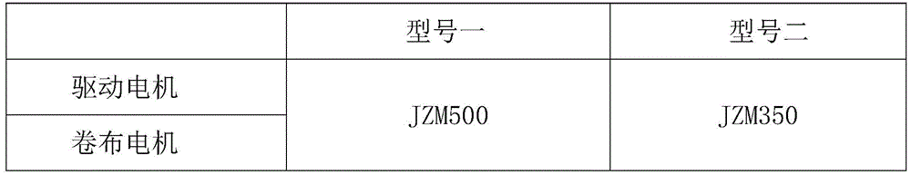
The electric appliance model in the above table is only two kinds of scheme selection that this embodiment can use, and other electric elements that accord with this embodiment operation requirement are all can, and cylinder, batching motor and driving motor all are provided with rather than supporting control switch, and cylinder, batching motor and driving motor are respectively through supporting control switch and external power electric connection, and control switch's mounted position can select according to the in-service use needs.
In the description herein, references to the description of "one embodiment," "an example," "a specific example," etc., mean that a particular feature, structure, material, or characteristic described in connection with the embodiment or example is included in at least one embodiment or example of the invention. In this specification, the schematic representations of the terms used above do not necessarily refer to the same embodiment or example. Furthermore, the particular features, structures, materials, or characteristics described may be combined in any suitable manner in any one or more embodiments or examples.
The preferred embodiments of the present invention disclosed above are intended only to help illustrate the present invention. The preferred embodiments are not intended to be exhaustive or to limit the invention to the precise embodiments disclosed. Obviously, many modifications and variations are possible in light of the above teaching. The embodiments were chosen and described in order to best explain the principles of the invention and its practical applications, to thereby enable others skilled in the art to best understand the invention for and utilize the invention. The present invention is limited only by the claims and their full scope and equivalents.
Claims (7)
1. The utility model provides a dedicated automatic cloth rewinder that removes dust of all cotton flannel processing, includes plummer (1), its characterized in that: the dust removal device is characterized in that baffle covers (2) are symmetrically and fixedly connected to the left side and the right side of the rear side of the top of the bearing platform (1), two groups of baffle covers (2) are arranged on one side, close to each other, of an inner cavity of each baffle cover (2), drum columns (3) are arranged on the outer walls of the two groups of drum columns (3), first rotating shafts (5) are fixedly connected to the upper ends and the lower ends of the two groups of drum columns (3), the top of each first rotating shaft (5) at the upper end is connected with the corresponding baffle cover (2) in a switching mode, the lower ends of the first rotating shafts (5) are connected with the bearing platform (1) in a switching mode, the bottoms of the first rotating shafts (5) at the lower ends penetrate through the bottom of the bearing platform (1), a supporting plate (6) is arranged at the bottom of the bearing platform (1), supporting leg columns (7) are fixedly connected to the left end and the right end of the front side wall and the left, a driving motor (8) and a dust collector (9) are arranged at the top of the supporting plate (6), the driving motor (8) is located on the front side of the dust collector (9), the power output end of the top of the driving motor (8) is connected with one end, penetrating through the bottom of the bearing table (1), of the first rotating shaft (5) on the left side of the lower end of the driving motor (8), gears (10) are fixedly connected to one ends, penetrating through the bottom of the bearing table (1), of the two groups of first rotating shafts (5) on the lower end of the lower end;
a vertical plate (11) is fixedly connected to the left side of the top of the bearing table (1), a cylinder (12) is arranged on the left side wall of the vertical plate (11), a cross plate (13) is fixedly connected to the top power telescopic end of the cylinder (12), the right end of the cross plate (13) penetrates through the right side wall of the vertical plate (11), the cross plate (13) is in sliding connection with the vertical plate (11), a cloth rolling roller (14) is arranged on the right side of the vertical plate (11), the cloth rolling roller (14) is located on the front side of the baffle cover (2), second rotating shafts (15) are symmetrically inserted into the upper end and the lower end of the cloth rolling roller (14), the top of each second rotating shaft (15) at the upper end is in switching connection with the corresponding cross plate (13), the bottom of each second rotating shaft (15) at the lower end is in switching connection with the bearing table (1), the bottom of each second rotating shaft (15) at the lower end penetrates through the bottom of the bearing table (1), and baffle discs (16) are fixedly connected, two groups of baffle discs (16) are respectively positioned at the upper side and the lower side of the cloth rolling roller (14), a cloth rolling motor (17) is arranged at the front side of the bottom of the bearing table (1), and the power output end at the top of the cloth rolling motor (17) is connected with one end of a second rotating shaft (15) at the lower end, which penetrates through the bottom of the bearing table (1);
two sets of keep off the one end that the inner chamber rear side wall of cover (2) was pressed close to each other and has all been seted up into dirt window (19), and is two sets of the one end symmetry that the front side of advancing dirt window (19) was kept away from each other is provided with and keeps off a class board (20), and keeps off the rear side wall of class board (20) and keep off cover (2) looks rigid coupling, the upper surface rear side of plummer (1) is seted up and is dodged groove (21) with Y shape dust absorption hose (18) matched with, and dodges the inner chamber lower surface of groove (21) and runs through the lower surface of plummer (1), the input of the left and right sides of Y shape dust absorption hose (18) all communicates has dust guiding box cover (22), and the inner chamber of dust guiding box cover (22) corresponds with the inner chamber that keeps off cover (2) through advancing dirt window.
2. The automatic dust-removing cloth rolling machine special for processing all-cotton flannelette as claimed in claim 1, is characterized in that: the dust removal fiber drum brush (4) is in clearance fit with the flow baffle plate (20).
3. The automatic dust-removing cloth rolling machine special for processing all-cotton flannelette as claimed in claim 1, is characterized in that: supporting rib plates are symmetrically and fixedly connected to the front end and the rear end of the bottom of the left side wall of the vertical plate (11), and the bottoms of the supporting rib plates are fixedly connected with the bearing table (1).
4. The automatic dust-removing cloth rolling machine special for processing all-cotton flannelette as claimed in claim 1, is characterized in that: the top of riser (11) is seted up with horizontal board (13) matched with holding tank, the guide way has been seted up to both sides wall symmetry around the inner chamber of holding tank, the both sides wall symmetry rigid coupling has the guide block with guide way matched with around horizontal board (13).
5. The automatic dust-removing cloth rolling machine special for processing all-cotton flannelette as claimed in claim 4, wherein: the connecting part between the guide block and the guide groove is subjected to smoothing treatment.
6. The automatic dust-removing cloth rolling machine special for processing all-cotton flannelette as claimed in claim 1, is characterized in that: limiting concave holes are symmetrically formed in the left side and the right side of the bottom of the cloth rolling roller (14), and limiting protrusions matched with the limiting concave holes are symmetrically arranged on the left side and the right side of the top of the baffle disc (16) at the lower end of the cloth rolling roller.
7. The automatic dust-removing cloth rolling machine special for processing all-cotton flannelette as claimed in claim 1, is characterized in that: the bottoms of the four groups of supporting leg columns (7) are provided with non-slip mats.
Priority Applications (1)
| Application Number | Priority Date | Filing Date | Title |
|---|---|---|---|
| CN202020726256.1U CN212334081U (en) | 2020-05-02 | 2020-05-02 | Cloth rewinder that dedicated automation of all cotton flannel processing removed dust |
Applications Claiming Priority (1)
| Application Number | Priority Date | Filing Date | Title |
|---|---|---|---|
| CN202020726256.1U CN212334081U (en) | 2020-05-02 | 2020-05-02 | Cloth rewinder that dedicated automation of all cotton flannel processing removed dust |
Publications (1)
| Publication Number | Publication Date |
|---|---|
| CN212334081U true CN212334081U (en) | 2021-01-12 |
Family
ID=74079156
Family Applications (1)
| Application Number | Title | Priority Date | Filing Date |
|---|---|---|---|
| CN202020726256.1U Active CN212334081U (en) | 2020-05-02 | 2020-05-02 | Cloth rewinder that dedicated automation of all cotton flannel processing removed dust |
Country Status (1)
| Country | Link |
|---|---|
| CN (1) | CN212334081U (en) |
-
2020
- 2020-05-02 CN CN202020726256.1U patent/CN212334081U/en active Active
Similar Documents
| Publication | Publication Date | Title |
|---|---|---|
| CN110790059B (en) | Adjustable cloth feeding brush device for spinning and using method | |
| CN213358037U (en) | Setting machine of moisture absorption sweat-releasing antibacterial sportswear fabric | |
| CN212334081U (en) | Cloth rewinder that dedicated automation of all cotton flannel processing removed dust | |
| CN206755817U (en) | A kind of fabric drying unit for clothes processing | |
| CN112404039A (en) | A leftover bits recovery unit for fabrics production | |
| CN210238110U (en) | Textile fabric finishing equipment with ironing function | |
| CN116926807A (en) | Efficient washing system for jean fabric spinning and washing process thereof | |
| CN216404867U (en) | Polyester fabric production and processing is with dust collecting equipment that removes hair | |
| CN109023886A (en) | A kind of spinning dust collector | |
| CN213208375U (en) | Textile fabric drying device for spinning | |
| CN213951705U (en) | Textile surface treatment device | |
| CN212895478U (en) | Dust removal device of fiber sanding machine | |
| CN108211552A (en) | A kind of weaving dust removal device | |
| CN212714058U (en) | Textile fabric cleaning device | |
| CN107326637A (en) | A kind of textile cloth dust arrester | |
| CN207913405U (en) | Weaving dust removal device | |
| CN113494015A (en) | Two-sided defeathering dust collecting equipment is used in dacron surface fabric production and processing | |
| CN112281287A (en) | Equipment for absorbing and treating textile dust of textile machine | |
| CN219586396U (en) | Pressing machine for fabric processing | |
| CN217005126U (en) | High-efficient drying and shaping device is used in polypropylene fiber processing | |
| CN107442477A (en) | One kind weaving frame dust arrester | |
| CN218722902U (en) | Drying mechanism for silk processing | |
| CN217052539U (en) | Fly frame fine hair cleaning device | |
| CN214496775U (en) | Energy-saving box type dyeing machine | |
| CN115948904B (en) | Collecting device is got rid of to fabrics hair ball |
Legal Events
| Date | Code | Title | Description |
|---|---|---|---|
| GR01 | Patent grant | ||
| GR01 | Patent grant |