CN212322897U - Load switch for clean and dry air insulated metal-enclosed switchgear - Google Patents
Load switch for clean and dry air insulated metal-enclosed switchgear Download PDFInfo
- Publication number
- CN212322897U CN212322897U CN202021002121.7U CN202021002121U CN212322897U CN 212322897 U CN212322897 U CN 212322897U CN 202021002121 U CN202021002121 U CN 202021002121U CN 212322897 U CN212322897 U CN 212322897U
- Authority
- CN
- China
- Prior art keywords
- vacuum
- main
- vacuum arc
- chamber
- static contact
- Prior art date
- Legal status (The legal status is an assumption and is not a legal conclusion. Google has not performed a legal analysis and makes no representation as to the accuracy of the status listed.)
- Active
Links
Images


Abstract
A load switch for clean and dry air insulated metal enclosed switchgear, it is a technical field of power switch, overcome the problem that the clean and dry air insulated switchgear is poor in arc extinguishing ability and complicated in structure, high in cost, many components, bulky among the prior art, the characteristic is to install the stop pin on the upper stationary contact, fixedly connect with the arc extinguish chamber drive plate on the main knife, fixedly install the auxiliary knife on the upper portion of the vacuum arc extinguish chamber assembly, the vacuum arc extinguish chamber assembly is installed between two main knives in parallel and can rotate relative to two main knives, install the sliding pin on the inferior part of the vacuum arc extinguish chamber assembly, the beneficial effects are, simple in construction, low in cost, small, and because the vacuum arc extinguish chamber only finishes breaking the load current, the bearing of the load current and closing of the short-circuit current are finished by the main knife, therefore cancel the internal shielding tube and internal magnetic field system used for short-circuit current breaking, the external dimensions of the vacuum interrupter are reduced by 70% compared to the prior art.
Description
Technical Field
The utility model belongs to the technical field of power switch, in particular to a load switch for clean and dry air insulation metal-enclosed switchgear.
Background
The load switch is an important electrical element on the inflatable ring network switch cabinet, and the functions of the load switch comprise the switching of load current and the switching of short-circuit current, so that the load switch plays an important role in the whole power supply system. In the prior art, load switches for gas-insulated metal-enclosed switchgear are divided into three types, the first type being SF6Knife switch type load switch with gas as insulating and arc extinguishing medium, wherein electric arc generated in switch opening and closing process is SF6The gas is extinguished, completing the opening and closing of the circuit, but due to the SF6The load switch product is greenhouse effect gas which is emission reduction gas specified by the Kyoto protocol, has the problems of pollution and damage to the environment, and brings adverse effects to the normal operation of electrical equipment and the health of people. The second type is a pneumatic load switch, in the switching-on and switching-off process of the switch, high-pressure gas generated by the movement of a piston per se blows out electric arcs, the structure is complex, the cost is high, the sealing problem of the high-pressure gas and the burning problem of an arc extinguishing contact are difficult to solve, and the arc extinguishing contact needs to be maintained or replaced regularly; the third is a vacuum load switch, which utilizes the vacuum arc extinguishing principle to extinguish electric arcs in the switching-on and switching-off process, the fracture of the vacuum arc extinguishing chamber of the load switch can not be used as a safety fracture, a disconnecting switch is required to be connected in series to be used as the safety fracture, and the vacuum load switch has the advantages of more elements, large volume, complex structure and high cost.
The utility model with application number of CN201620690543.5 (CN 205811405U) provides an environment-friendly dry air insulation ring main unit, the utility model comprises a ring main body, a cable chamber arranged in the ring main body, a white steel gas tank arranged in the ring main body, a three-position isolating switch arranged in the ring main body, wherein the cable chamber is arranged at the inner bottom of the ring main body, a pressure relief chamber is arranged at the inner bottom of the ring main body at the rear side of the cable chamber, a vacuum load switch is arranged at the upper part of the pressure relief chamber, the three-position isolating switch is arranged at the upper part of the vacuum load switch, and is connected with a vacuum load switch, a first push-out wire sleeve is arranged at the upper part of the ring main body, the first push-out wire sleeve extends into the ring main body, and is matched with a three-station isolating switch, one side of the ring main body is provided with an operating mechanism for controlling a vacuum load switch, the lower part of the vacuum load switch is connected with a conductive connecting rod, and the lower part of the conductive connecting rod is connected with a second wire ejection sleeve. The utility model discloses an adopt compressed dry air as insulating medium, have green's characteristics. However, this utility model discloses seal primary member such as vacuum load switch, circuit breaker and three-station isolator in the casing that uses dry air as insulating medium, all high-pressure parts all seal in the white steel gas tank promptly, and used three-station isolator establishes ties in the gas tank with vacuum load switch in the looped netowrk cabinet, and three-station isolator and vacuum load switch are operated by the outside mechanism of gas tank respectively, and the structure is complicated, and is with high costs.
The invention with the application number of CN200710019229.X (CN 101030500A) discloses a vacuum load switch for a high-voltage fixed switch cabinet, which comprises an upper outgoing line of a disconnecting link, an isolation tool apron, a vacuum arc-extinguishing chamber, a lower moving contact, a lower outgoing line seat, a connecting bus, a cable outgoing board, an isolation tool insulating pull rod assembly, an arc-extinguishing chamber insulating pull rod assembly, an operating mechanism and a grounding device, wherein the isolation disconnecting link is connected with the vacuum arc-extinguishing chamber in series, the isolation tool insulating pull rod assembly and the arc-extinguishing chamber insulating pull rod assembly are both in transmission connection with the operating mechanism, the isolation tool apron, the vacuum arc-extinguishing chamber and the lower outgoing line seat are fixedly sealed together, a hinged end of the isolation disconnecting link is provided with a contact finger spring, the contact finger springs are respectively contacted with the isolation disconnecting link and the isolation tool apron, and a movable end of the vacuum arc-extinguishing chamber is provided with. The invention meets the requirement of environmental protection, has better insulating capability, but has more complex structure, large size and high cost, and is not beneficial to the miniaturization of products.
The utility model discloses a utility model with application number CN201220171659.X (CN 202957217U) "isolator and vacuum circuit breaker combined system", isolator and vacuum circuit breaker cascade connection constitute the combined switch system that isolation fracture and vacuum interrupter fracture are correlated with, keep apart the fracture and separate the dead zone for one between isolator's isolation switch and vacuum circuit breaker's the moving contact tail end, the vacuum interrupter fracture separates the dead zone for another between vacuum circuit breaker's moving contact and the static contact. According to the record of this utility model specification is visible, this utility model vacuum circuit breaker is equipped with the limiting plate, and is equipped with the separating brake spring between limiting plate and moving contact, and this utility model is an utilize separating brake spring drive vacuum interrupter separating brake, at vacuum interrupter separating brake in-process simultaneous drive isolator moving contact synchronous motion, after vacuum interrupter separating brake targets in place, the separating brake spring stops external acting, and the isolator moving contact relies on inertia separating brake to target in place. The vacuum interrupter has the requirement of switching-off speed, when the switching-off spring drives the moving contact of the vacuum interrupter and the moving contact of the isolating switch to move at the same speed, the switching-off spring is required to provide energy larger than that of the moving contact of the vacuum interrupter which is only operated, and the energy of the switching-off spring is provided and stored by the isolating switch mechanism in the switching-on process, so that the operating mechanism of the isolating switch is more complex and the cost is higher. Because the brake-separating speed and the friction force can be different every time, the moving contact of the isolating switch is difficult to ensure that the synchronous brake-separating can be reliably carried out in place every time and every phase by means of inertia brake-separating, and the insulating capability of an isolating fracture can be reduced due to the difference until breakdown discharge accidents are caused. In addition, this utility model the structure be that isolator and vacuum interrupter establish ties in the isolator outside, utilize the linear motion drive vacuum interrupter's of isolator moving contact linear motion, realize the return circuit combined floodgate, the problem of existence is, because vacuum interrupter will accomplish the arc extinguishing function, it is very fast to closing a floodgate speed requirement, this will lead to isolator to both export great stroke, will have very high speed again, isolator's operating device will become very complicated, the cost improves.
SUMMERY OF THE UTILITY MODEL
The utility model aims to solve the problem overcome prior art weak point and defect, provide one kind and both accorded with the environmental protection requirement, can improve clean and dry air insulated switchgear's arc extinguishing ability again, and simple structure, with low costs and do benefit to the miniaturized load switch who is used for clean and dry air insulated metal enclosed switchgear of product.
The load switch of the utility model is of a three-phase structure, each phase comprises an upper static contact, a main knife, a vacuum arc-extinguishing chamber component, a lower static contact and a fixed insulating bracket, the upper static contact and the lower static contact are connected with the fixed insulating bracket, a main driving shaft is arranged in the round holes of 3 lower static contacts, a locking pin is arranged on the upper static contact, an arc-extinguishing chamber driving plate is arranged on the main knife, the arc-extinguishing chamber driving plate is fixedly connected with the main knife, the main knife is tightly pressed on the upper static contact through an upper tension spring and is tightly pressed on the lower static contact through a lower tension spring, an auxiliary knife is fixedly arranged on the upper part of the vacuum arc-extinguishing chamber component, the vacuum arc-extinguishing chamber component is arranged between 2 main knives in parallel and can rotate relative to the 2 main knives, a sliding pin is arranged on the lower part of the vacuum arc-extinguishing chamber, when the vacuum arc extinguish chamber component rotates along with the main driving shaft under the driving of the 2 main cutters, the sliding pin slides back and forth along the curve guide groove on the arc extinguish chamber driving plate, so that the vacuum arc extinguish chamber component is respectively positioned at the closing position of the vacuum arc extinguish chamber or the separating position of the vacuum arc extinguish chamber.
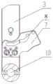
The vacuum arc extinguish chamber component comprises encapsulated silica gel, a vacuum arc extinguish chamber, a reset spring hanging plate, a movable end wire outlet seat, a vacuum arc extinguish chamber static contact and a vacuum arc extinguish chamber moving contact, wherein the upper end of the vacuum arc extinguish chamber is connected with an auxiliary knife, the lower end of the vacuum arc extinguish chamber is connected with a sliding pin through the movable end wire outlet seat, and a reset spring is hung on the reset spring hanging plate.
The main cutter and the auxiliary cutter are both processed by copper plates.
The diameters of the static contact and the moving contact of the vacuum arc extinguish chamber are 12-14 mm, the distance between the static contact and the moving contact of the vacuum arc extinguish chamber is 5-6 mm,
the outer diameter of the vacuum arc-extinguishing chamber is 37mm, and the height of the vacuum arc-extinguishing chamber is 64 mm.
Compared with the prior art, the beneficial effects of the utility model are that
(1) The utility model discloses a parallelly connected combination of main sword and vacuum interrupter becomes load switch, realizes separately solving load switch's the problem of closing of short-circuit current and load current's the problem of breaking, and closing of short-circuit current is accomplished to main sword, and vacuum interrupter accomplishes the breaking of load current, has avoided electric arc among the clean dry air to ablate the contact problem, and does not have SF6The use of gas, the product simple structure, it is with low costs.
(2) The utility model discloses every looks vacuum interrupter installs between two main swoves, vacuum interrupter and 2 main swoves are parallelly connected, during the combined floodgate, main sword and vacuum interrupter rotate in step, accomplish and close the operation, main sword parts earlier and reaches safe distance during the separating brake, because the circuit is put through by vacuum interrupter, main sword and last static contact room can not produce electric arc, part behind the vacuum interrupter, the electric arc is extinguished to the vacuum interrupter part of the in-process, electric arc extinguishes the back, vacuum interrupter gets back to between two main swoves, the outside operating device who is connected rather than only need provide the rotatory energy of main sword, therefore simple structure, and is low in cost.
(3) The utility model discloses the same main shaft of three-phase sharing of main sword is by the outside operating device synchronous operation rather than being connected, and the divide-shut brake position all has fixed spacing part in outside operating device, and the three-phase synchronism is good, can guarantee reliable, accurate be in the divide-shut brake position.
(4) Because vacuum interrupter only accomplishes the load current that opens and shuts, load current's the inside magnetic field system who bears and short-circuit current is broken by main sword completion, consequently vacuum interrupter compares with prior art, has cancelled an internal shield section of thick bamboo and is used for short-circuit current to open and shut, has reduced the diameter of the inside sound contact of vacuum interrupter, has reduced the opening range of the inside sound contact of vacuum interrupter, has consequently reduced vacuum interrupter's overall size, vacuum interrupter's external diameter is 37mm, highly is 64mm, compares the volume with prior art and has reduced 70%, consequently, the vacuum interrupter subassembly is the vacuum interrupter who miniaturizes and the structure simplification, simple structure, with low costs, small, does benefit to the miniaturization of product.
Drawings
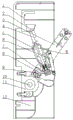
Fig. 1 is a schematic structural diagram of the present invention;
FIG. 2 is a schematic structural diagram of the main blade switching-on position and the vacuum arc-extinguishing chamber switching-on position of the present invention,
FIG. 3 is a schematic structural view of the middle position of the main knife and the switch-off position of the vacuum arc-extinguishing chamber of the present invention,
FIG. 4 is a schematic structural diagram of the main blade opening position and the vacuum interrupter closing position of the present invention,
FIG. 5 is a schematic diagram of a vacuum interrupter chamber assembly;
fig. 6 is an assembly schematic of the main knife, arc chute drive plate and spindle.
In the figure:
1. an upper static contact is arranged on the upper static contact,
2. a locking pin is arranged on the base plate,
3. the main knife is a main knife, and the main knife,
4. an auxiliary knife is arranged on the knife body,
5. a vacuum arc-extinguishing chamber component is arranged on the vacuum arc-extinguishing chamber component,
5-1, encapsulating silica gel, 5-2, a vacuum arc-extinguishing chamber,
5-2-1, a static contact of the vacuum arc-extinguishing chamber, 5-2-2, a moving contact of the vacuum arc-extinguishing chamber,
5-3, a reset spring hanging plate, 5-4 a movable end outgoing line seat,
6. a return spring is arranged on the upper end of the shell,
7. an arc extinguish chamber drive plate is arranged on the arc extinguish chamber,
8. a curved guide groove is formed on the upper surface of the guide groove,
9. a sliding pin is arranged on the sliding block,
10. a main drive shaft is provided on the main drive shaft,
11. a lower static contact is arranged on the lower static contact,
12. the insulating bracket is fixed on the base plate,
13. an upper tension spring is arranged on the upper side of the frame,
14. a lower tension spring is arranged on the lower part of the lower part,
A. the vacuum arc-extinguishing chamber is closed,
B. and (4) separating the vacuum arc extinguish chambers.
Detailed Description
As shown in fig. 1 to 6, the load switch of the present invention is a three-phase structure, each phase includes an upper static contact 1, 2 main blades 3, a vacuum arc-extinguishing chamber assembly 5, a main driving shaft 10 and a lower static contact 11, the upper static contact 1 and the lower static contact 11 are connected to a fixed insulating support 12 through screws, the main driving shaft 10 is installed in a circular hole of the 3 lower static contacts 11, the main driving shaft 10 is a hexagonal shaft, one end of the main driving shaft 10 extends out and is connected to an operating mechanism, the main driving shaft 10 can freely rotate in the circular holes of the 3 lower static contacts 11, a locking pin 2 is installed on the upper static contact 1, an arc-extinguishing chamber driving plate 7 is fixedly connected to the 2 main blades 3 through rivets, the arc-extinguishing chamber driving plate 7 and the main blades 3 are correspondingly processed with hexagonal holes and are sleeved on the main driving shaft 10 together and rotate together with the main driving shaft 10, the 2 main knives 3 are tightly pressed on the upper static contact 1 through an upper tension spring 13 and are also tightly pressed on the lower static contact 11 through a lower tension spring 14, and the vacuum arc extinguish chamber component 5 comprises encapsulated silica gel 5-1, a vacuum arc extinguish chamber 5-2, a reset spring hanging plate 5-3, a movable end wire outlet base 5-4, a vacuum arc extinguish chamber static contact 5-2-1 and a vacuum arc extinguish chamber movable contact 5-2-2; the upper end of the vacuum arc extinguish chamber 5-2 is connected with an auxiliary knife 4, a reset spring 6 is hung on a reset spring hanging plate 5-3, the vacuum arc extinguish chamber component 5 is installed between 2 main knives 3 and can rotate relative to the two main knives 3, a sliding pin 9 is connected on a lower movable end wire outlet seat 5-4 of the vacuum arc extinguish chamber component 5, a curve guide groove 8 is formed in an arc extinguish chamber drive plate 7, the vacuum arc extinguish chamber component 5 rotates relative to the main knives 3 under the action of the reset spring 6 and a locking pin 2, the sliding pin 9 slides back and forth along the curve guide groove 8 in the arc extinguish chamber drive plate 7, and the vacuum arc extinguish chamber 5-2 is enabled to be respectively located in a vacuum arc extinguish chamber combination position A or a vacuum arc extinguish chamber division position B.
The vacuum arc extinguish chamber component 5 of the utility model is an arc extinguish chamber which is miniaturized and simplified in structure, has simple structure and low cost, and the main functions of the load switch in the power system can be load bearing and open and close load current and close short circuit current, the vacuum arc extinguish chamber component 5 only completes the on-off load current, and the load bearing of the load current and the close and close of the short circuit current are completed by the main knife, therefore, compared with the prior art, the vacuum arc extinguish chamber 5-2 of the utility model cancels an internal shielding cylinder and an internal magnetic field system for the on-off of the short circuit current, and simultaneously reduces the diameters of an internal vacuum arc extinguish chamber static contact 5-2-1 and a vacuum moving contact 5-2-2 of the vacuum arc extinguish chamber, the diameters of the vacuum arc extinguish chamber static contact 5-2-1 and the vacuum moving contact 5-2-2 are 12-14 mm, the opening distance between the static contact 5-2-1 of the vacuum arc extinguish chamber and the movable contact 5-2-2 of the vacuum arc extinguish chamber is 5-6 mm, so that the overall size of the vacuum arc extinguish chamber 5-2 is reduced, the diameter of the vacuum arc extinguish chamber is only 37mm, the height of the vacuum arc extinguish chamber is 64mm, and the volume of the vacuum arc extinguish chamber is reduced by 70 percent compared with the prior art; the main knife 3 is formed by processing a copper plate, and the load current bearing and the short circuit current closing are completed in the structure of the utility model; the auxiliary knife 4 is also formed by processing a copper plate, and the structure of the utility model is matched with a vacuum arc extinguish chamber 5-2 to complete the on-off of the load current.
As shown in fig. 2, during a closing operation, 2 main blades 3 drive the vacuum interrupter chamber assembly 5 to rapidly move to a closing position in a counterclockwise direction, and are pressed and contacted with the upper stationary contact 1 under the action of the upper tension spring 13, and in this process, if a short circuit occurs in a loop, the main blades 3 complete closing of a short-circuit current; if no short circuit occurs in the loop, the main knife 3 completes the closing of the load current; after closing, the load current flows through a loop formed by the upper static contact 1, the main knife 3 and the lower static contact 11, and no load current flows through the vacuum arc-extinguishing chamber component 5; the auxiliary knife 4 on the upper part of the vacuum arc-extinguishing chamber assembly 5 moves along with the vacuum arc-extinguishing chamber assembly 5, and when the switch is closed, the auxiliary knife 4 goes over the locking pin 2 on the upper static contact 1 and is locked by the locking pin 2.
As shown in fig. 3, during the opening operation, the main drive shaft 10 drives the main knife 3 to rotate clockwise, and after the main knife 3 is separated from the upper static contact 1, the load current briefly flows through a loop formed by the upper static contact 1, the locking pin 2, the auxiliary knife 4, the vacuum arc extinguishing chamber assembly 5, the main knife 3 and the lower static contact 11; the locking pin 2 blocks the vacuum arc extinguish chamber component 5 to move together with the main knife 3, so that the vacuum arc extinguish chamber component 5 rotates relative to the main knife 3, the sliding pin 9 at the lower part of the vacuum arc extinguish chamber component 5 slides along the curve guide groove 8 on the arc extinguish chamber driving sheet 7, the vacuum arc extinguish chamber 5-2 is separated to the vacuum arc extinguish chamber separation position B, and load current is cut off.
As shown in fig. 4, the main driving shaft 10 continues to operate the main knife 3 to rotate, the vacuum interrupter chamber assembly 5 continues to rotate relative to the main knife 3, the auxiliary knife 4 gradually slides away from the locking pin 2, the vacuum interrupter chamber assembly 5 rotates in the opposite direction relative to the main knife 3 under the action of the return spring 6, returns to the middle of the 2 main knives 3 and reaches the switching-off position along with the main knife 3, in the process, the sliding pin 9 at the lower part of the vacuum interrupter 5 slides in the opposite direction along the curved guide groove 8 on the interrupter driving piece, so that the vacuum interrupter 5-2 is switched on to the vacuum interrupter combination position a to prepare for switching off the load current at the next time.
Claims (5)
1. A load switch for a clean and dry air insulated metal enclosed switchgear, the load switch is of a three-phase structure, each phase comprises an upper static contact (1), a main knife (3), a vacuum arc-extinguishing chamber component (5), a lower static contact (11) and a fixed insulating support (12), the upper static contact (1) and the lower static contact (11) are connected with the fixed insulating support (12), and a main driving shaft (10) is installed in a circular hole of the 3 lower static contacts (11), the load switch is characterized in that a locking pin (2) is installed on the upper static contact (1), an arc-extinguishing chamber driving plate (7) is installed on the main knife (3), the arc-extinguishing chamber driving plate (7) is fixedly connected with the main knife (3), the main knife (3) is tightly pressed on the upper static contact (1) through an upper tension spring (13) and is tightly pressed on the lower static contact (11) through a lower tension spring (14), the utility model discloses a vacuum arc extinguishing chamber, including vacuum arc extinguishing chamber subassembly (5), the upper portion fixed mounting of vacuum arc extinguishing chamber subassembly (5) has auxiliary knife (4), vacuum arc extinguishing chamber subassembly (5) parallel mount between 2 main knives (3) and can rotate for 2 main knives (3), installs sliding pin (9) in the lower part of vacuum arc extinguishing chamber subassembly (5) be equipped with curve guide way (8) on explosion chamber drive plate (7), when vacuum arc extinguishing chamber subassembly (5) rotate along with main drive shaft (10) under the drive of 2 main knives (3), sliding pin (9) make a round trip to slide along curve guide way (8) on explosion chamber drive plate (7), make vacuum arc extinguishing chamber subassembly (5) be in vacuum arc extinguishing chamber closed position (A) or vacuum arc extinguishing chamber branch position (B) respectively.
2. The load switch for the clean and dry air-insulated metal-enclosed switchgear according to claim 1, wherein the vacuum interrupter chamber assembly (5) comprises encapsulated silica gel (5-1), a vacuum interrupter (5-2), a reset spring hanging plate (5-3), a movable terminal outlet base (5-4), a static contact (5-2-1) of the vacuum interrupter chamber and a movable contact (5-2-2) of the vacuum interrupter chamber, the upper end of the vacuum interrupter chamber (5-2) is connected with an auxiliary knife (4), the lower end of the vacuum interrupter chamber (5-2) is connected with a sliding pin (9) through the movable terminal outlet base (5-4), and a reset spring (6) is hung on the reset spring hanging plate (5-3).
3. The load switch for clean and dry air insulated metal enclosed switchgear according to claim 1 or 2, wherein the main blade (3) and the auxiliary blade (4) are both machined from copper plate.
4. The load switch for the clean and dry air insulated metal enclosed switchgear according to claim 2, wherein the diameter of the vacuum interrupter static contact (5-2-1) and the vacuum interrupter moving contact (5-2-2) is 12-14 mm, and the distance between the vacuum interrupter static contact (5-2-1) and the vacuum interrupter moving contact (5-2-2) is 5-6 mm.
5. The load switch for clean dry air insulated metal enclosed switchgear according to claim 2, characterized in that the vacuum interrupter (5-2) has an outer diameter of 37mm and a height of 64 mm.
Priority Applications (1)
| Application Number | Priority Date | Filing Date | Title |
|---|---|---|---|
| CN202021002121.7U CN212322897U (en) | 2020-06-04 | 2020-06-04 | Load switch for clean and dry air insulated metal-enclosed switchgear |
Applications Claiming Priority (1)
| Application Number | Priority Date | Filing Date | Title |
|---|---|---|---|
| CN202021002121.7U CN212322897U (en) | 2020-06-04 | 2020-06-04 | Load switch for clean and dry air insulated metal-enclosed switchgear |
Publications (1)
| Publication Number | Publication Date |
|---|---|
| CN212322897U true CN212322897U (en) | 2021-01-08 |
Family
ID=74026819
Family Applications (1)
| Application Number | Title | Priority Date | Filing Date |
|---|---|---|---|
| CN202021002121.7U Active CN212322897U (en) | 2020-06-04 | 2020-06-04 | Load switch for clean and dry air insulated metal-enclosed switchgear |
Country Status (1)
| Country | Link |
|---|---|
| CN (1) | CN212322897U (en) |
Cited By (1)
| Publication number | Priority date | Publication date | Assignee | Title |
|---|---|---|---|---|
| CN115603217A (en) * | 2022-12-12 | 2023-01-13 | 石家庄科林电气设备有限公司(Cn) | Load switch and environment-friendly gas-insulated combined electrical appliance ring main unit |
-
2020
- 2020-06-04 CN CN202021002121.7U patent/CN212322897U/en active Active
Cited By (2)
| Publication number | Priority date | Publication date | Assignee | Title |
|---|---|---|---|---|
| CN115603217A (en) * | 2022-12-12 | 2023-01-13 | 石家庄科林电气设备有限公司(Cn) | Load switch and environment-friendly gas-insulated combined electrical appliance ring main unit |
| CN115603217B (en) * | 2022-12-12 | 2023-03-24 | 石家庄科林电气设备有限公司 | Load switch and environment-friendly gas-insulated combined electrical appliance ring main unit |
Similar Documents
| Publication | Publication Date | Title |
|---|---|---|
| CN104145318B (en) | A kind of vacuum interrupter with fixing fracture | |
| CN106384961A (en) | Gas insulated bus grounding device | |
| CN107359068B (en) | Moulded case circuit breaker with compound arc extinguishing performance | |
| CN115602480B (en) | Three-position switch and three-position environment-friendly gas combined electrical appliance ring main unit | |
| CN112216550B (en) | Column circuit breaker with built-in isolating switch | |
| CN111463061A (en) | Vacuum arc-extinguishing chamber and vacuum circuit breaker | |
| CN212322897U (en) | Load switch for clean and dry air insulated metal-enclosed switchgear | |
| CN115967037A (en) | Rotary and direct-acting combined pneumatic type environment-friendly gas load switch cabinet | |
| CN109659190B (en) | Built-in isolated vacuum arc-extinguishing chamber device and vacuum circuit breaker | |
| US5750949A (en) | Metal-encapsulated, gas-insulated high-voltage circuit-breaker | |
| CN111540641A (en) | Load switch for clean and dry air insulated metal-enclosed switchgear | |
| CN115603217B (en) | Load switch and environment-friendly gas-insulated combined electrical appliance ring main unit | |
| US4000387A (en) | Puffer-type gas circuit-interrupter | |
| CN217934787U (en) | Arc extinguish chamber for gas insulation switch cabinet | |
| CN216353930U (en) | GIS is with two break isolator | |
| CN114783816B (en) | Circuit breaker | |
| CN104465256B (en) | Arc extinguishing chamber for isolation breaker and isolation breaker comprising same | |
| CN211879293U (en) | Isolation integrated switch of air insulation circuit breaker | |
| CN109786172B (en) | Built-in isolated vacuum arc-extinguishing chamber component and vacuum circuit breaker | |
| CN109524912B (en) | Integrated circuit breaker and switch cabinet | |
| CN109755065B (en) | Arc extinguishing mechanism for load switch | |
| CN107342196B (en) | Arc extinguishing device of high-breaking plastic casing type circuit breaker | |
| CN112071719A (en) | Circuit breaker opening and closing contact mechanism and circuit breaker | |
| CN217691037U (en) | Breaking device, circuit breaker and electrical equipment | |
| CN218384969U (en) | 10kV dry air load switch |
Legal Events
| Date | Code | Title | Description |
|---|---|---|---|
| GR01 | Patent grant | ||
| GR01 | Patent grant |