CN115602480B - Three-position switch and three-position environment-friendly gas combined electrical appliance ring main unit - Google Patents
Three-position switch and three-position environment-friendly gas combined electrical appliance ring main unit Download PDFInfo
- Publication number
- CN115602480B CN115602480B CN202211587709.7A CN202211587709A CN115602480B CN 115602480 B CN115602480 B CN 115602480B CN 202211587709 A CN202211587709 A CN 202211587709A CN 115602480 B CN115602480 B CN 115602480B
- Authority
- CN
- China
- Prior art keywords
- arc
- main
- grounding
- contact
- auxiliary
- Prior art date
- Legal status (The legal status is an assumption and is not a legal conclusion. Google has not performed a legal analysis and makes no representation as to the accuracy of the status listed.)
- Active
Links
Images


Classifications
-
- H—ELECTRICITY
- H01—ELECTRIC ELEMENTS
- H01H—ELECTRIC SWITCHES; RELAYS; SELECTORS; EMERGENCY PROTECTIVE DEVICES
- H01H31/00—Air-break switches for high tension without arc-extinguishing or arc-preventing means
- H01H31/02—Details
-
- H—ELECTRICITY
- H01—ELECTRIC ELEMENTS
- H01H—ELECTRIC SWITCHES; RELAYS; SELECTORS; EMERGENCY PROTECTIVE DEVICES
- H01H3/00—Mechanisms for operating contacts
- H01H3/32—Driving mechanisms, i.e. for transmitting driving force to the contacts
- H01H3/38—Driving mechanisms, i.e. for transmitting driving force to the contacts using spring or other flexible shaft coupling
-
- H—ELECTRICITY
- H01—ELECTRIC ELEMENTS
- H01H—ELECTRIC SWITCHES; RELAYS; SELECTORS; EMERGENCY PROTECTIVE DEVICES
- H01H31/00—Air-break switches for high tension without arc-extinguishing or arc-preventing means
- H01H31/003—Earthing switches
-
- H—ELECTRICITY
- H01—ELECTRIC ELEMENTS
- H01H—ELECTRIC SWITCHES; RELAYS; SELECTORS; EMERGENCY PROTECTIVE DEVICES
- H01H33/00—High-tension or heavy-current switches with arc-extinguishing or arc-preventing means
- H01H33/60—Switches wherein the means for extinguishing or preventing the arc do not include separate means for obtaining or increasing flow of arc-extinguishing fluid
- H01H33/66—Vacuum switches
- H01H33/664—Contacts; Arc-extinguishing means, e.g. arcing rings
-
- H—ELECTRICITY
- H01—ELECTRIC ELEMENTS
- H01H—ELECTRIC SWITCHES; RELAYS; SELECTORS; EMERGENCY PROTECTIVE DEVICES
- H01H33/00—High-tension or heavy-current switches with arc-extinguishing or arc-preventing means
- H01H33/60—Switches wherein the means for extinguishing or preventing the arc do not include separate means for obtaining or increasing flow of arc-extinguishing fluid
- H01H33/66—Vacuum switches
- H01H33/666—Operating arrangements
- H01H33/6661—Combination with other type of switch, e.g. for load break switches
-
- H—ELECTRICITY
- H02—GENERATION; CONVERSION OR DISTRIBUTION OF ELECTRIC POWER
- H02B—BOARDS, SUBSTATIONS OR SWITCHING ARRANGEMENTS FOR THE SUPPLY OR DISTRIBUTION OF ELECTRIC POWER
- H02B13/00—Arrangement of switchgear in which switches are enclosed in, or structurally associated with, a casing, e.g. cubicle
- H02B13/02—Arrangement of switchgear in which switches are enclosed in, or structurally associated with, a casing, e.g. cubicle with metal casing
- H02B13/035—Gas-insulated switchgear
- H02B13/0354—Gas-insulated switchgear comprising a vacuum switch
-
- H—ELECTRICITY
- H02—GENERATION; CONVERSION OR DISTRIBUTION OF ELECTRIC POWER
- H02B—BOARDS, SUBSTATIONS OR SWITCHING ARRANGEMENTS FOR THE SUPPLY OR DISTRIBUTION OF ELECTRIC POWER
- H02B13/00—Arrangement of switchgear in which switches are enclosed in, or structurally associated with, a casing, e.g. cubicle
- H02B13/02—Arrangement of switchgear in which switches are enclosed in, or structurally associated with, a casing, e.g. cubicle with metal casing
- H02B13/035—Gas-insulated switchgear
- H02B13/075—Earthing arrangements
Abstract
The invention provides a three-position switch and a three-position environment-friendly gas combined electrical appliance ring main unit, which belong to the technical field of high-voltage electrical equipment and comprise a frame, a swinging mechanism, a disconnecting link mechanism and a track mechanism, wherein the frame comprises a front plate and a rear plate which are parallel to each other; the swing mechanism comprises a swing frame and main shafts arranged at the front end and the rear end of the swing frame, and the swing frame realizes reciprocating swing by means of the operating mechanism; the main shaft is connected to the front plate and the rear plate; the disconnecting link mechanism is limited on the swing frame; the track mechanism comprises two parallel support rods and an arc-shaped guide rail, two ends of the arc-shaped guide rail are respectively fixed on the two support rods, and two ends of the support rods are supported on the front plate and the rear plate; the swing mechanism drives the knife switch mechanism to slide along the arc-shaped guide rail, so that the three-station switch is in a closing state, an isolation state and a grounding state. The main switch adopts a linkage scheme, has simple structure, can realize the opening and closing action of the arc extinguish chamber and the action of the three-position switch by only one operating mechanism, and is easy to operate.
Description
Technical Field
The invention belongs to the technical field of high-voltage electrical equipment, and particularly relates to a three-position switch and a three-position environment-friendly gas combined electrical appliance ring main unit.
Background
In recent years, SF is used 6 The application of load switch-fuse combined electrical apparatus (hereinafter referred to as combined electrical apparatus) using gas as insulating medium in power distribution system is becoming more and more extensive. The combined electrical apparatus has the technical advantages of simple electrical wiring, rapid protection action, convenient maintenance work and the like, and economic advantages of high cost performance and the like, and is widely applied to medium and small-capacity transformer users. But SF 6 The gas is a greenhouse gas with serious harm and is limited in use and emission, so that a combined electrical cabinet taking environment-friendly gas as an insulating medium is needed to replace SF 6 A combined electrical appliance cabinet.
The existing combined electrical cabinet taking environment-friendly gas as an insulating medium needs two operating shafts and two sets of operating mechanisms, one set of operating mechanisms is responsible for the closing and opening actions of an arc extinguish chamber, the other set of operating mechanisms is responsible for the closing and opening actions of an isolating switch, and the actions of the two operating mechanisms are required to be sequential, so that a three-position switch can be operated after the vacuum arc extinguish chamber breaks a circuit, the three-position switch does not allow live operation, and the operation is complex.
Disclosure of Invention
The embodiment of the invention provides a three-station environment-friendly gas combined electrical appliance ring main unit which is simple in structure, can realize the opening and closing actions of an arc extinguish chamber and the three-station switch actions by only one operating mechanism and is easy to operate.
In order to achieve the above object, in a first aspect, the present invention adopts the following technical solutions: there is provided a three-position switch comprising:
a frame including a front plate and a rear plate parallel to each other;
the swinging mechanism comprises a swinging frame and main shafts arranged at the front end and the rear end of the swinging frame, and the swinging frame realizes reciprocating swinging by means of the operating mechanism; the main shaft is connected to the front plate and the rear plate;
the disconnecting link mechanism is limited on the swinging frame; and
the track mechanism comprises two parallel supporting rods and an arc-shaped guide rail, two ends of the arc-shaped guide rail are respectively fixed on the two supporting rods, and two ends of the supporting rods are supported on the front plate and the rear plate; the swinging mechanism drives the disconnecting link mechanism to slide along the arc-shaped guide rail, so that the three-station switch is in a closing state, an isolating state and a grounding state.
With reference to the first aspect, in one possible implementation manner, the disconnecting link mechanism includes a disconnecting link support, a duckbill contact, a vacuum arc-extinguishing chamber, an outgoing line copper bar, a separating gate spring, an over-travel assembly, an adjusting rod and a roller;
the knife switch bracket comprises vertical plates which are parallel to each other, and a first fixing plate, a second fixing plate, a third fixing plate and a fourth fixing plate which are vertically connected among the vertical plates from top to bottom;
the vacuum arc-extinguishing chamber is limited between the first fixing plate and the second fixing plate; the duckbilled contact is connected to the static end of the vacuum arc extinguish chamber, the overtravel assembly is connected to the movable end of the vacuum arc extinguish chamber, and the outgoing copper bar is fixed to the movable end of the vacuum arc extinguish chamber and moves along with the movable end; the overtravel assembly is limited between the third fixing plate and the fourth fixing plate, and the opening spring is sleeved on the overtravel assembly and compressed between the third fixing plate and the overtravel assembly; the adjusting rod is connected to one end, far away from the vacuum arc extinguish chamber, of the over travel assembly, and the roller is connected to the lower end of the adjusting rod;
the knife switch mechanism slides along the arc-shaped guide rail through the roller, the switching-off spring stretches, the vacuum arc extinguish chamber is switched on or switched off, the main loop circuit is switched on or switched off, and the three-station switch is in a switching-on state, an isolation state and a grounding state.
With reference to the first aspect, in a possible implementation manner, a lower boss is disposed at a lower end of the arc-shaped guide rail, an upper boss is disposed at an upper end of the arc-shaped guide rail, the roller is in a closing state when abutting against the lower boss, the roller is in a grounding state when abutting against the upper boss, and the roller is in an isolation state when being between the upper boss and the lower boss.
With reference to the first aspect, in a possible implementation manner, the swing frame includes two parallel support plates and a plurality of connecting rods connected between the two support plates, and a vertical plate of the disconnecting link mechanism is fixed between the connecting rods that are bilaterally symmetric; the main shaft is assembled on the supporting plate.
With reference to the first aspect, in a possible implementation manner, a protruding positioning block is disposed on the vertical plate, and the positioning block is matched with the positioning hole on the connecting rod.
In a second aspect, an embodiment of the present invention further provides a three-position ring main unit for an environment-friendly gas combined electrical apparatus, including the three-position switch.
With reference to the second aspect, in a possible implementation manner, the electric connector further includes a cabinet, side expansion sleeves, a three-position switch, a fuse assembly, a main grounding contact, a main grounding copper bar, a wire outlet sleeve and an auxiliary grounding mechanism, wherein the side expansion sleeves are symmetrically arranged on left and right side plates of the cabinet, a main bus is connected between two symmetrical side expansion sleeves, and the duckbill contact is in contact with the main bus; the fuse component is arranged below the three-position switch, the outgoing copper bar is connected with the fuse component through a flexible connecting copper wire and a branch bus, and the fuse component is connected with the outgoing sleeve through an outgoing bus; the main grounding contact is mounted on one side plate of the cabinet body, and the main grounding copper bar is connected with the main grounding contact and the lower end of the cabinet body; when the disconnecting link mechanism slides to a grounding state, the duckbill contact leaves the main bus to be in contact with the main grounding contact; the auxiliary grounding mechanism is connected between the main shaft and the fuse assembly.
With reference to the second aspect, in one possible implementation manner, the flexible connecting copper wire and the branch bus bar are fixed on the arc-shaped guide rail at an intersection point.
With reference to the second aspect, in a possible implementation manner, the auxiliary grounding mechanism includes a connecting rod assembly, an auxiliary shaft, an auxiliary disconnecting link and an auxiliary grounding contact, an upper end of the connecting rod assembly is connected to the main shaft, and a lower end of the connecting rod assembly is connected to the auxiliary shaft; the auxiliary disconnecting link is connected to the auxiliary shaft, and the auxiliary grounding contact is mounted on the fuse assembly; and the main shaft rotates to enable the connecting rod assembly to drive the auxiliary disconnecting link to be in contact with or separate from the auxiliary grounding contact.
With reference to the second aspect, in one possible implementation manner, the connecting rod assembly includes an upper crank arm, a first connecting rod, a second connecting rod, a transmission rod and a lower crank arm, which are sequentially hinged, and the upper crank arm is connected to the spindle; the lower crank arm is connected to the auxiliary shaft, a first track groove and a second track groove are formed in the rear plate, a first hinge shaft between the first connecting rod and the second connecting rod is limited on the first track groove, and a second hinge shaft between the second connecting rod and the transmission rod is limited on the second track groove; the first track groove comprises an upper arc-shaped groove and a lower arc-shaped groove, and the radius of the lower arc-shaped groove is equal to that of the second connecting rod; the second track groove is a straight line groove in the vertical direction.
Compared with the prior art, the three-position switch and the three-position environment-friendly gas combined electric appliance ring main unit provided by the invention have the beneficial effects that: the main switch adopts a linkage scheme, has a simple structure, can realize the opening and closing action of the arc extinguish chamber and the action of the three-station switch by only one operating mechanism, and is easy to operate.
Drawings
Fig. 1 is a first schematic structural diagram of a three-station environment-friendly gas combined electrical appliance ring main unit according to an embodiment of the present invention;
fig. 2 is a schematic structural diagram ii of a three-station environment-friendly gas combined electrical appliance ring main unit according to an embodiment of the present invention;
fig. 3 is a third schematic structural diagram of a three-station environment-friendly gas combined electrical appliance ring main unit according to an embodiment of the present invention;
fig. 4 is a schematic structural diagram of a ring main unit of a three-station environment-friendly gas combined electrical appliance according to an embodiment of the present invention;
fig. 5 is a schematic structural diagram five of the three-station environment-friendly gas combined electrical appliance ring main unit provided in the embodiment of the present invention;
fig. 6 is a schematic structural diagram six of a three-station environment-friendly gas combined electrical appliance ring main unit provided in the embodiment of the present invention;
fig. 7 is a first schematic structural diagram of a three-position switch according to an embodiment of the present invention;
fig. 8 is a schematic structural diagram ii of a three-position switch according to an embodiment of the present invention;
fig. 9 is a schematic structural diagram three of a three-position switch provided in the embodiment of the present invention;
fig. 10 is a schematic structural diagram of a three-position switch according to an embodiment of the present invention;
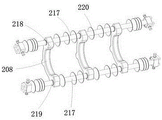
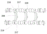
fig. 11 is a first schematic structural diagram of a track mechanism of a three-position switch according to an embodiment of the present invention;
fig. 12 is a second schematic structural diagram of a track mechanism of a three-position switch according to an embodiment of the present invention;
FIG. 13 is a schematic structural view of a three-position switch with a track-off mechanism according to an embodiment of the present invention;
fig. 14 is a schematic structural diagram of a disconnecting link mechanism of a three-position switch according to an embodiment of the present invention;
fig. 15 is a schematic structural diagram of a swing mechanism of a three-position switch according to an embodiment of the present invention;
fig. 16 is a schematic structural diagram of a back plate of a three-position switch according to an embodiment of the present invention;
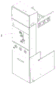
fig. 17 is a first schematic view of an appearance structure of a three-station environment-friendly gas combined electrical appliance ring main unit according to an embodiment of the present invention;
fig. 18 is a schematic view of an appearance structure of a ring main unit of a three-station environment-friendly gas combined electrical appliance according to an embodiment of the present invention;
fig. 19 is a third schematic view of an appearance structure of the three-station environment-friendly gas combined electrical appliance ring main unit according to the embodiment of the invention;
description of the reference numerals:
1. a cabinet body; 2. a three-position switch; 201. a back plate; 202. a main shaft; 203. a first track groove; 204. a second track groove; 205. a duckbill contact; 206. a front plate; 207. a support plate; 208. an arc-shaped guide rail; 209. a roller; 210. a connecting rod; 211. a vacuum arc-extinguishing chamber; 212. a brake separating spring; 213. adjusting a rod; 214. a flexible connection copper wire; 215. an outgoing line copper bar; 216. an over-travel assembly; 217. a support bar; 218. an upper boss; 219. a lower boss; 220. a silica gel umbrella; 221. a first fixing plate; 222. a second fixing plate; 223. a third fixing plate; 224. a fourth fixing plate; 225. a vertical plate; 226. positioning blocks; 3. a transmission rod; 4. a fuse assembly; 5. an auxiliary ground contact; 6. an auxiliary knife switch; 7. an outgoing line bus; 8. a wire outlet sleeve; 9. an interlocking mechanism; 10. an operating mechanism; 11. a branch bus; 12. laterally expanding a sleeve; 13. a main bus; 14. an auxiliary shaft; 15. a first hinge shaft; 16. a second hinge shaft; 17. an upper crank arm; 18. a first link; 19. a second link; 20. a main ground contact; 21. a lower crank arm; 22. a main ground copper bar.
Detailed Description
In order to make the technical problems, technical solutions and advantageous effects to be solved by the present invention more clearly apparent, the present invention is further described in detail below with reference to the accompanying drawings and embodiments. It should be understood that the specific embodiments described herein are merely illustrative of the invention and are not intended to limit the invention.
In the description of the present invention, it should be noted that, if terms indicating orientation or positional relationship such as "front", "rear", "left", "right", "up", "down", etc. appear, they are orientation or positional relationship based on the use state of the ring main unit, and the front direction refers to the direction toward the operation panel, which is only for convenience of describing the present invention and simplifying the description, but does not indicate or imply that the device or element referred to must have a specific orientation, be configured and operated in a specific orientation, and thus, should not be construed as limiting the present invention.
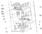
Referring to fig. 1 to 19 together, a ring main unit of a three-station environmental protection gas combination appliance provided by the present invention will be described. The three-station environment-friendly gas combined electric appliance ring main unit comprises a frame, a swinging mechanism, a disconnecting link mechanism and a track mechanism, wherein the frame comprises a front plate 206 and a rear plate 201 which are parallel to each other; the swing mechanism comprises a swing frame and main shafts 202 arranged at the front end and the rear end of the swing frame, and the swing frame realizes reciprocating swing by means of the operating mechanism 10; the main shaft 202 is connected to the front plate 206 and the rear plate 201; the disconnecting link mechanism is limited on the swing frame; the track mechanism comprises two parallel supporting rods 217 and an arc-shaped guide rail 208, two ends of the arc-shaped guide rail 208 are respectively fixed on the two supporting rods 217, and two ends of the supporting rods 217 are supported on the front plate 206 and the rear plate 201; the swing mechanism drives the knife switch mechanism to slide along the arc-shaped guide rail 208, so that the three-position switch 2 is in a closing state, an isolation state and a grounding state.
Compared with the prior art, the three-position switch 2 and the three-position environment-friendly gas combined electrical appliance ring main unit provided by the invention have the beneficial effects that: the main switch adopts a linkage scheme, has a simple structure, can realize the opening and closing actions of the arc extinguish chamber and the actions of the three-position switch 2 only by one operating mechanism 10, and is easy to operate.
It should be noted that the three-position switch 2 provided in this embodiment needs to be coordinated with other mechanisms of the cabinet 1 in the opening and closing actions to clearly explain the action relationship, and therefore, the actions of the embodiments are not separately explained herein, but the operation process is finally explained in the text in a unified manner, so as to improve the continuity and intelligibility of the actions.
It should also be noted that the present disclosure is only illustrative of a three-position switch. For the ring main unit, the ring main unit further comprises an air box, an operating mechanism and an interlocking mechanism 9 in the main unit body, which are conventional designs of the ring main unit and are not described herein again.
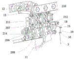
In some embodiments, as shown in fig. 1 to 16, the disconnecting link mechanism comprises a disconnecting link bracket, a duckbill contact 205, a vacuum arc extinguish chamber 211, an outlet copper bar 215, a separating link spring 212, an over travel assembly 216, an adjusting rod 213 and a roller 209; the knife switch bracket comprises vertical plates 225 which are parallel to each other, and a first fixing plate 221, a second fixing plate 222, a third fixing plate 223 and a fourth fixing plate 224 which are vertically connected among the vertical plates 225 from top to bottom; the vacuum arc-extinguishing chamber 211 is limited between the first fixing plate 221 and the second fixing plate 222; the duckbilled contact 205 is connected to the static end of the vacuum arc extinguish chamber 211, the over travel assembly 216 is connected to the moving end of the vacuum arc extinguish chamber 211, and the outgoing copper bar 215 is fixed to the moving end of the vacuum arc extinguish chamber 211 and moves along with the moving end; the overtravel assembly 216 is limited between the third fixing plate 223 and the fourth fixing plate 224, and the opening spring 212 is sleeved on the overtravel assembly 216 and compressed between the third fixing plate 223 and the overtravel assembly 216; the adjusting rod 213 is connected to one end of the over travel assembly 216 far away from the vacuum arc-extinguishing chamber 211, and the roller 209 is connected to the lower end of the adjusting rod 213; the knife switch mechanism slides along the arc-shaped guide rail 208 through the roller 209, the switching-off spring 212 stretches, the vacuum arc extinguish chamber 211 is switched on or switched off, the main loop circuit is switched on or switched off, and the three-station switch 2 is in a switching-on state, an isolation state and a grounding state.
The opening spring 212 is in a compressed state, the opening spring 212 pushes the over travel assembly 216, and the over travel assembly 216 pulls the movable end of the arc extinguish chamber, so that the interior of the arc extinguish chamber is in an opening state. The adjustment lever 213 is in contact with the arc guide 208, and the arc guide 208 restricts the position of the adjustment lever 213.
In some embodiments, as shown in fig. 11 to 12, a lower boss 219 is disposed at a lower end of the arc-shaped guide rail 208, an upper boss 218 is disposed at an upper end of the arc-shaped guide rail 208, the roller 209 is in a closed state when abutting against the lower boss 219, the roller 209 is in a grounded state when abutting against the upper boss 218, and the roller 209 is in an isolated state when being between the upper boss 218 and the lower boss 219.
In some embodiments, as shown in fig. 1 to 16, the swing frame includes two parallel support plates 207 and a plurality of connecting rods 210 connected between the two support plates 207, and the vertical plate 225 of the disconnecting link mechanism is fixed between the connecting rods 210 which are symmetrical left and right; the main shaft 202 is mounted on a support plate 207.
In some embodiments, as shown in fig. 13 to 15, a protruding positioning block 226 is disposed on the vertical plate 225, and the positioning block 226 is engaged with the positioning hole of the connecting rod 210. Still be equipped with silica gel umbrella 220 on the connecting rod 210, increased creepage distance.
In the above embodiments, the descriptions of the respective embodiments have respective emphasis, and reference may be made to the related descriptions of other embodiments for parts that are not described or illustrated in a certain embodiment.
Based on the same inventive concept, the embodiment of the application also provides a three-station environment-friendly gas combined electrical appliance ring main unit, which comprises the three-station switch 2.
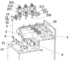
The embodiment of the application also provides a three-station environment-friendly gas combined electrical appliance ring main unit, as shown in fig. 1 to 19, the three-station environment-friendly gas combined electrical appliance ring main unit further comprises a cabinet body 1, side expansion sleeves 12, a three-station switch 2, a fuse assembly 4, a main grounding contact 20, a main grounding copper bar 22, an outlet sleeve 8 and an auxiliary grounding mechanism, wherein the side expansion sleeves 12 are symmetrically arranged on the left side plate and the right side plate of the cabinet body 1, a main bus 13 is connected between the two symmetrical side expansion sleeves 12, and a duckbilled contact 205 is in contact with the main bus 13; the fuse component 4 is arranged below the three-position switch 2, the outgoing copper bar 215 is connected with the fuse component 4 through a flexible connecting copper line 214 and a branch bus 11, and the fuse component 4 is connected with the outgoing sleeve 8 through an outgoing bus 7; the main grounding contact 20 is arranged on one side plate of the cabinet body 1, when the disconnecting link mechanism slides to a grounding state, the duckbill contact 205 leaves the main bus 13 to be in contact with the main grounding contact 20, and the main grounding copper bar is connected with the main grounding contact and the lower end of the cabinet body; the auxiliary grounding mechanism is connected between the main shaft 202 and the fuse assembly 4.
During operation, electric energy enters the three-position switch 2 through the main bus 13, then enters the fuse assembly 4, and finally flows out through the outgoing line sleeve 8.
The cabinet body 1 is also internally provided with an air box, an operating mechanism 10 and an interlocking mechanism, the side expanding sleeve 12, the three-position switch 2, the fuse component 4, the main grounding contact 20, the outgoing line sleeve 8 and the auxiliary grounding mechanism are positioned in the air box, and the operating mechanism 10 and the interlocking mechanism are externally arranged outside the air box. The operating mechanism 10 is connected with a main shaft 202 of the three-position switch 2 through a dynamic seal. And an interlock mechanism for providing an interlock function to prevent a malfunction. The bottom of the cabinet body 1 is a cable chamber.
The working principle of the ring main unit provided by the invention is as follows:
when the three-position switch 2 is in a switching-on position, the disconnecting link mechanism is in a vertical state, the duckbilled contact 205 is in contact with the main bus 13 in the air box, the roller 209 slides to the lower boss 219 of the arc-shaped guide rail 208, the adjusting rod 213 moves upwards to drive the over-travel assembly 216 to overcome the resistance of the switching-off spring 212, so that the vacuum arc extinguish chamber 211 is switched on, and the main circuit is switched on and is in a switching-on state.
When the three-station switch 2 moves from the switching-on position to the isolation position, the operating mechanism 10 drives the main shaft 202 to rotate, the main shaft 202 drives the swing frame to rotate, the swing frame drives the disconnecting link mechanism to rotate, the roller 209 leaves the lower boss 219 and moves along the arc-shaped guide rail 208, the disconnecting link spring 212 extends to drive the over-travel assembly 216 to move downwards, the vacuum arc-extinguishing chamber 211 is subjected to tripping first under the action of the disconnecting link spring 212, the main circuit is disconnected, at the moment, the duckbilled contact 205 has a certain width, the duckbilled contact 205 is still connected with the main bus 13, the disconnecting link mechanism continues to rotate, the adjusting rod 213 moves along the arc-shaped part of the arc-shaped guide rail 208, and the vacuum arc-extinguishing chamber 211 keeps tripping until the duckbilled contact 205 is separated from the main bus 13 and is in an isolation state.
When the three-position switch 2 moves from the isolation position to the grounding position, the duckbill contact 205 has a certain width and contacts with the main grounding contact 20 first, at this time, the vacuum arc-extinguishing chamber 211 is still in the switching-off state, the knife-switch mechanism continues to rotate, the adjusting rod 213 moves from the arc part of the arc guide rail 208 to the upper boss 218 of the arc guide rail 208, and under the action of the upper boss 218, the adjusting rod 213 moves inwards to overcome the acting force of the switching-off spring 212, so that the arc-extinguishing chamber is switched on and is in the grounding state. At this time, the auxiliary grounding mechanism is grounded.
The operation mechanism 10 operates in the reverse direction to drive the main shaft 202 to rotate in the reverse direction, the duckbill contact 205 moves from the grounding position to the isolation position in the reverse direction, and then moves from the isolation position to the switching-on position in the reverse direction, and the movement process is performed in the reverse direction.
When in a closing state, high-voltage current enters from the main bus 13, passes through the three-position switch 2 and the fuse component 4 in sequence, and finally flows out from the outlet sleeve 8. The high-voltage loop can generate electric arcs in the brake separating process, and the electric arcs can not be extinguished and explode due to the fact that the duckbill contact 205 is directly used for separating the circuit, so that the electric arcs need to be extinguished through the vacuum arc extinguishing chamber 211 in the brake separating process, and the duckbill contact 205 and the main bus 13 are separated after the loop is cut off; high-voltage circuit is when closing a floodgate, if there is short circuit fault in the downstream circuit, very big short circuit current can appear in the circuit, when using duckbill contact 205 directly to close a floodgate, can produce a large amount of heats, make duckbill contact 205 and main bus 13 fusion welding together, unable separating brake, can explode when serious, so before closing a floodgate, duckbill contact 205 just contacts main bus 13 when, because vacuum interrupter 211 is in the separating brake state, no electric current passes through in the circuit, after duckbill contact 205 and main bus 13 complete contact, vacuum interrupter 211 adjusts pole 213 and reaches arc guide rail 208's last boss 218, under last boss 218 effect, vacuum interrupter 211 closes a floodgate.
Therefore, no matter the disconnecting link mechanism is switched on or switched on to ground from an isolation position to a switching-on position or a grounding position, the motion sequence is that the duckbill contact 205 is firstly contacted with the main bus 13 (grounding contact), and the vacuum arc-extinguishing chamber 211 is switched on after the duckbill contact is in place; from the switching-on position (grounding position) to the isolation position, the switching-off of the vacuum arc extinguish chamber 211 is firstly carried out, and the duckbill contact 205 is separated from the main bus 13 (grounding contact).
In some embodiments, as shown in fig. 8, the intersection of the flexible connecting copper wire 214 and the branch bus bar 11 is fixed on the arc-shaped guide rail 208.
In some embodiments, as shown in fig. 1 to 10, the auxiliary grounding mechanism includes a link assembly, an auxiliary shaft 14, an auxiliary knife-switch 6 and an auxiliary grounding contact 5, the upper end of the link assembly is connected to the main shaft 202, and the lower end is connected to the auxiliary shaft 14; the auxiliary knife switch 6 is connected to the auxiliary shaft 14, and the auxiliary grounding contact 5 is arranged on the fuse component 4; the main shaft 202 rotates, so that the connecting rod assembly drives the auxiliary knife switch 6 to contact or separate from the auxiliary grounding contact 5. The auxiliary shaft 14 is a square shaft, which is convenient for driving the lower crank arm 21 and the auxiliary knife switch 6 to rotate in a follow-up manner.
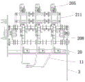
In some embodiments, as shown in fig. 1 to 10 and 16, the connecting rod assembly comprises an upper crank arm 17, a first connecting rod 18, a second connecting rod 19, a transmission rod 3 and a lower crank arm 21 which are hinged in sequence, wherein the upper crank arm 17 is connected to a main shaft 202; the lower crank arm 21 is connected to the auxiliary shaft 14, the rear plate 201 is provided with a first track groove 203 and a second track groove 204, a first hinge shaft 15 between the first connecting rod 18 and the second connecting rod 19 is limited on the first track groove 203, and a second hinge shaft 16 between the second connecting rod 19 and the transmission rod 3 is limited on the second track groove 204; wherein, the first track groove 203 comprises an upper arc-shaped groove and a lower arc-shaped groove, and the radius of the lower arc-shaped groove is the second connecting rod 19; the second track groove 204 is a straight groove in the vertical direction.
Through the crank arms, the connecting rods, the track grooves, the transmission rod 3 and other components, the three-station movement (grounding-isolation-closing) of the main shaft 202 is converted into two stations of an auxiliary grounding switch (grounding-isolation), and the auxiliary grounding switch does not act in the process of the isolation and closing conversion of the main shaft 202. The auxiliary grounding switch is arranged to increase the safety in the maintenance process.
Supplementary ground mechanism is along with the action of three station switch 2, sees from cabinet body operation face, and the process is as follows:
when the main shaft 202 of the three-position switch 2 rotates from the isolation position to the closing position, the upper crank arm 17 rotates clockwise to drive the first connecting rod 18 and the first hinge shaft 15 to move rightwards, and due to the limitation of the angle of the upper crank arm 17 and the first track groove 203, the second connecting rod 19 moves clockwise by taking the second hinge shaft 16 as the center of a circle, the second hinge shaft 16 does not move, and the transmission rod 3 does not move.
When the main shaft 202 of the three-position switch 2 rotates from the isolation position to the grounding position, the upper crank arm 17 rotates counterclockwise to drive the first connecting rod 18 and the first hinge shaft 15 to move upward leftward, so as to drive the second connecting rod 19 to move upward, the second connecting rod 19 drives the transmission rod 3 to move upward, the transmission rod 3 drives the lower crank arm 21 to rotate, the lower crank arm 21 drives the auxiliary shaft 14 to rotate, and the auxiliary shaft 14 drives the auxiliary knife switch 6 to rotate toward the auxiliary grounding contact and to contact with the auxiliary grounding contact, so that the auxiliary grounding function is realized.
When the three-position switch 2 is located at the isolation position, the transmission rod 3 drives the lower crank arm 21 to enable the auxiliary disconnecting link 6 and the auxiliary grounding contact to be in a separated state. When the three-position switch 2 rotates from the isolation position to the switching-on position, the auxiliary grounding switch does not act and is still in a separated state because the transmission rod 3 is not moved. When the three-position switch 2 rotates from the isolation position to the grounding position, the transmission rod 3 moves upwards to drive the auxiliary shaft 14 to rotate, and the auxiliary disconnecting link 6 rotates to be in contact with the auxiliary grounding contact, so that the auxiliary grounding function is realized.
The above description is only for the purpose of illustrating the preferred embodiments of the present invention and is not to be construed as limiting the invention, and any modifications, equivalents and improvements made within the spirit and principle of the present invention are intended to be included within the scope of the present invention.
Claims (9)
1. A three-position switch, comprising:
a frame comprising a front plate (206) and a rear plate (201) parallel to each other;
the swinging mechanism comprises a swinging frame and main shafts (202) arranged at the front end and the rear end of the swinging frame, and the swinging frame realizes reciprocating swinging by means of an operating mechanism (10); the main shaft (202) is connected to the front plate (206) and the rear plate (201);
the disconnecting link mechanism is limited on the swinging frame; and
the track mechanism comprises two parallel supporting rods (217) and an arc-shaped guide rail (208), two ends of the arc-shaped guide rail (208) are respectively fixed on the two supporting rods (217), and two ends of the supporting rods (217) are supported on the front plate (206) and the rear plate (201); the swinging mechanism drives the disconnecting link mechanism to slide along the arc-shaped guide rail (208), so that the three-station switch is in a closing state, an isolating state and a grounding state;
the disconnecting link mechanism comprises a disconnecting link bracket, a duckbilled contact (205), a vacuum arc-extinguishing chamber (211), an outgoing line copper bar (215), a switching-off spring (212), an over-travel assembly (216), an adjusting rod (213) and a roller (209);
the knife switch bracket comprises vertical plates (225) which are parallel to each other, and a first fixing plate (221), a second fixing plate (222), a third fixing plate (223) and a fourth fixing plate (224) which are vertically connected between the vertical plates (225) from top to bottom;
the vacuum arc-extinguishing chamber (211) is limited between the first fixing plate (221) and the second fixing plate (222); the duckbilled contact (205) is connected to the static end of the vacuum arc-extinguishing chamber (211), the over-travel assembly (216) is connected to the moving end of the vacuum arc-extinguishing chamber (211), and the outgoing line copper bar (215) is fixed to the moving end of the vacuum arc-extinguishing chamber (211) and moves along with the moving end; the overtravel assembly (216) is limited between the third fixing plate (223) and the fourth fixing plate (224), and the opening spring (212) is sleeved on the overtravel assembly (216) and compressed between the third fixing plate (223) and the overtravel assembly (216); the adjusting rod (213) is connected to one end, away from the vacuum arc-extinguishing chamber (211), of the over-travel assembly (216), and the roller (209) is connected to the lower end of the adjusting rod (213);
the knife switch mechanism slides along the arc-shaped guide rail (208) through the roller (209), the switching-off spring (212) stretches, the vacuum arc extinguish chamber (211) is switched on or switched off, a main loop circuit is switched on or switched off, and the three-station switch is in a switching-on state, an isolation state and a grounding state.
2. The three-position switch of claim 1, wherein a lower boss (219) is disposed at a lower end of the arc-shaped guide rail (208), an upper boss (218) is disposed at an upper end of the arc-shaped guide rail (208), the roller (209) is in a switch-on state when abutting against the lower boss (219), the roller (209) is in a ground state when abutting against the upper boss (218), and the roller (209) is in an isolation state when being positioned between the upper boss (218) and the lower boss (219).
3. The three-position switch according to claim 1, characterized in that said oscillating frame comprises two parallel supporting plates (207) and a plurality of connecting rods (210) connected between said two supporting plates (207), the vertical plates (225) of said disconnecting link mechanism being fixed between said connecting rods (210) which are bilaterally symmetrical; the main shaft (202) is mounted on the support plate (207).
4. The three-position switch according to claim 3, wherein the vertical plate (225) is provided with a protruding positioning block (226), and the positioning block (226) is matched with a positioning hole on the connecting rod (210).
5. A three-position environment-friendly gas combined electrical appliance ring main unit is characterized by comprising the three-position switch as claimed in any one of claims 1 to 4.
6. The three-station environment-friendly gas combined electric appliance ring main unit as claimed in claim 5, further comprising a main body (1), side expanding sleeves (12), a three-station switch, a fuse assembly (4), a main grounding contact (20), a main grounding copper bar (22), an outlet sleeve (8) and an auxiliary grounding mechanism, wherein the side expanding sleeves (12) are symmetrically arranged on left and right side plates of the main body (1), a main bus (13) is connected between two symmetrical side expanding sleeves (12), and the duckbill contact (205) is in contact with the main bus (13); the fuse component (4) is installed below the three-position switch, the outgoing copper bar (215) is connected with the fuse component (4) through a flexible connecting copper wire (214) and a branch bus (11), and the fuse component (4) is connected with the outgoing sleeve (8) through an outgoing bus (7); the main grounding contact (20) is mounted on one side plate of the cabinet body (1), and the main grounding copper bar (22) is connected with the main grounding contact (20); when the disconnecting link mechanism slides to a grounding state, the duckbill contact (205) leaves the main bus (13) to be in contact with the main grounding contact (20); the auxiliary grounding mechanism is connected between the main shaft (202) and the fuse assembly (4).
7. The ring main unit of the three-station environment-friendly gas combined electrical appliance according to claim 6, wherein the intersection point of the flexible connecting copper wire (214) and the branch bus (11) is fixed on the arc-shaped guide rail (208).
8. The ring main unit of the three-station environment-friendly gas combined electrical appliance according to claim 6, wherein the auxiliary grounding mechanism comprises a connecting rod assembly, an auxiliary shaft (14), an auxiliary disconnecting link (6) and an auxiliary grounding contact (5), the upper end of the connecting rod assembly is connected with the main shaft (202), and the lower end of the connecting rod assembly is connected with the auxiliary shaft (14); the auxiliary disconnecting link (6) is connected to the auxiliary shaft (14), and the auxiliary grounding contact (5) is installed on the fuse component (4); the main shaft (202) rotates, so that the connecting rod assembly drives the auxiliary disconnecting link (6) to be in contact with or separate from the auxiliary grounding contact (5).
9. The ring main unit of the three-station environment-friendly gas combined electrical appliance according to claim 8, wherein the connecting rod assembly comprises an upper crank arm (17), a first connecting rod (18), a second connecting rod (19), a transmission rod (3) and a lower crank arm (21) which are sequentially hinged, and the upper crank arm (17) is connected to the main shaft (202); the lower crank arm (21) is connected to the auxiliary shaft (14), a first track groove (203) and a second track groove (204) are formed in the rear plate (201), a first hinge shaft (15) between the first connecting rod (18) and the second connecting rod (19) is limited on the first track groove (203), and a second hinge shaft (16) between the second connecting rod (19) and the transmission rod (3) is limited on the second track groove (204); wherein the first track slot (203) comprises an upper arc-shaped slot and a lower arc-shaped slot, and the radius of the lower arc-shaped slot is the second connecting rod (19); the second track groove (204) is a straight groove in the vertical direction.
Priority Applications (1)
| Application Number | Priority Date | Filing Date | Title |
|---|---|---|---|
| CN202211587709.7A CN115602480B (en) | 2022-12-12 | 2022-12-12 | Three-position switch and three-position environment-friendly gas combined electrical appliance ring main unit |
Applications Claiming Priority (1)
| Application Number | Priority Date | Filing Date | Title |
|---|---|---|---|
| CN202211587709.7A CN115602480B (en) | 2022-12-12 | 2022-12-12 | Three-position switch and three-position environment-friendly gas combined electrical appliance ring main unit |
Publications (2)
| Publication Number | Publication Date |
|---|---|
| CN115602480A CN115602480A (en) | 2023-01-13 |
| CN115602480B true CN115602480B (en) | 2023-02-28 |
Family
ID=84853313
Family Applications (1)
| Application Number | Title | Priority Date | Filing Date |
|---|---|---|---|
| CN202211587709.7A Active CN115602480B (en) | 2022-12-12 | 2022-12-12 | Three-position switch and three-position environment-friendly gas combined electrical appliance ring main unit |
Country Status (1)
| Country | Link |
|---|---|
| CN (1) | CN115602480B (en) |
Families Citing this family (2)
| Publication number | Priority date | Publication date | Assignee | Title |
|---|---|---|---|---|
| CN116031766B (en) * | 2023-03-29 | 2023-06-20 | 石家庄科林电气设备有限公司 | Ring main unit capable of realizing in-place monitoring |
| CN116316242B (en) * | 2023-05-24 | 2023-08-08 | 江苏洛凯智能科技有限公司 | Isolated looped netowrk cabinet cubical switchboard |
Citations (9)
| Publication number | Priority date | Publication date | Assignee | Title |
|---|---|---|---|---|
| EP1739802A1 (en) * | 2005-06-29 | 2007-01-03 | Hitachi, Ltd. | Vacuum insulated switchgear |
| JP2007014087A (en) * | 2005-06-29 | 2007-01-18 | Hitachi Ltd | Vacuum insulation switchgear |
| CN109698089A (en) * | 2019-01-28 | 2019-04-30 | 广东安恒铁塔钢构有限公司 | A kind of tri-station isolating switch and atmospheric closed permanent-magnet breaker cabinet |
| CN110729657A (en) * | 2019-10-29 | 2020-01-24 | 江苏云峰科技股份有限公司 | Environment-friendly inflating cabinet |
| CN110854731A (en) * | 2019-11-13 | 2020-02-28 | 珠海许继电气有限公司 | Gas insulation switch equipment |
| CN210628176U (en) * | 2019-11-06 | 2020-05-26 | 厦门顾德益电器有限公司 | High-voltage switch |
| CN112382526A (en) * | 2020-10-22 | 2021-02-19 | 北京龙源开关设备有限责任公司 | Three station isolator integration circuit breakers on environment-friendly |
| CN113328370A (en) * | 2021-06-04 | 2021-08-31 | 长园电力技术有限公司 | Upper isolation upper grounding environment-friendly gas insulation ring main unit |
| CN115347495A (en) * | 2022-08-24 | 2022-11-15 | 王东 | Environment-friendly gas-insulated vacuum-opening-closing power distribution switch cabinet |
Family Cites Families (1)
| Publication number | Priority date | Publication date | Assignee | Title |
|---|---|---|---|---|
| CN215933459U (en) * | 2021-05-27 | 2022-03-01 | 默飓电气有限公司 | Three-position switch |
-
2022
- 2022-12-12 CN CN202211587709.7A patent/CN115602480B/en active Active
Patent Citations (9)
| Publication number | Priority date | Publication date | Assignee | Title |
|---|---|---|---|---|
| EP1739802A1 (en) * | 2005-06-29 | 2007-01-03 | Hitachi, Ltd. | Vacuum insulated switchgear |
| JP2007014087A (en) * | 2005-06-29 | 2007-01-18 | Hitachi Ltd | Vacuum insulation switchgear |
| CN109698089A (en) * | 2019-01-28 | 2019-04-30 | 广东安恒铁塔钢构有限公司 | A kind of tri-station isolating switch and atmospheric closed permanent-magnet breaker cabinet |
| CN110729657A (en) * | 2019-10-29 | 2020-01-24 | 江苏云峰科技股份有限公司 | Environment-friendly inflating cabinet |
| CN210628176U (en) * | 2019-11-06 | 2020-05-26 | 厦门顾德益电器有限公司 | High-voltage switch |
| CN110854731A (en) * | 2019-11-13 | 2020-02-28 | 珠海许继电气有限公司 | Gas insulation switch equipment |
| CN112382526A (en) * | 2020-10-22 | 2021-02-19 | 北京龙源开关设备有限责任公司 | Three station isolator integration circuit breakers on environment-friendly |
| CN113328370A (en) * | 2021-06-04 | 2021-08-31 | 长园电力技术有限公司 | Upper isolation upper grounding environment-friendly gas insulation ring main unit |
| CN115347495A (en) * | 2022-08-24 | 2022-11-15 | 王东 | Environment-friendly gas-insulated vacuum-opening-closing power distribution switch cabinet |
Also Published As
| Publication number | Publication date |
|---|---|
| CN115602480A (en) | 2023-01-13 |
Similar Documents
| Publication | Publication Date | Title |
|---|---|---|
| CN115602480B (en) | Three-position switch and three-position environment-friendly gas combined electrical appliance ring main unit | |
| CN102568910B (en) | 1100kV extra-high voltage series complement bypass switch | |
| CN109166747B (en) | DC load switch | |
| CN216750969U (en) | Gas insulation switch equipment | |
| CN100459008C (en) | Vacuum switch with up and low isolations | |
| CN202454479U (en) | 1100kV extra-high-voltage series-compensation by-pass switch | |
| EP2927926B1 (en) | Medium voltage switchgear comprising two switches per phase | |
| CN115603217B (en) | Load switch and environment-friendly gas-insulated combined electrical appliance ring main unit | |
| CN110233082B (en) | Permanent magnet vacuum circuit breaker and inflatable cabinet | |
| CN212322897U (en) | Load switch for clean and dry air insulated metal-enclosed switchgear | |
| CN106921122B (en) | Environment-friendly gas all-insulation all-sealed miniaturized switch cabinet | |
| CN104465256B (en) | Arc extinguishing chamber for isolation breaker and isolation breaker comprising same | |
| CN211879293U (en) | Isolation integrated switch of air insulation circuit breaker | |
| CN205230859U (en) | Be applied to plug -in type switching device's explosion chamber | |
| CN210296215U (en) | Permanent magnet vacuum circuit breaker and gas-filled cabinet | |
| CN111540641A (en) | Load switch for clean and dry air insulated metal-enclosed switchgear | |
| CN211957535U (en) | Transmission mechanism of side-mounted circuit breaker | |
| CN215009272U (en) | General type quick arc extinguisher that can move open | |
| CN205282365U (en) | Three station vacuum load switch - fuse combined electrical apparatuses of unit compartment cross -over connection formula | |
| CN219180459U (en) | Double-breakpoint frame circuit breaker | |
| CN217427473U (en) | Combined electrical switch equipment | |
| CN211296186U (en) | Movable type rapid arc extinguishing device and rapid arc extinguishing cabinet | |
| CN214227362U (en) | Ring main unit and three-position switch thereof | |
| CN202134455U (en) | Combined type high voltage change-over switch | |
| CN216389232U (en) | Circuit breaker |
Legal Events
| Date | Code | Title | Description |
|---|---|---|---|
| PB01 | Publication | ||
| PB01 | Publication | ||
| SE01 | Entry into force of request for substantive examination | ||
| SE01 | Entry into force of request for substantive examination | ||
| GR01 | Patent grant | ||
| GR01 | Patent grant |