CN212264244U - Straightening device for producing stainless steel pipe fitting for anastomat - Google Patents
Straightening device for producing stainless steel pipe fitting for anastomat Download PDFInfo
- Publication number
- CN212264244U CN212264244U CN202020380249.0U CN202020380249U CN212264244U CN 212264244 U CN212264244 U CN 212264244U CN 202020380249 U CN202020380249 U CN 202020380249U CN 212264244 U CN212264244 U CN 212264244U
- Authority
- CN
- China
- Prior art keywords
- fixedly connected
- stainless steel
- threaded
- steel pipe
- pipe fitting
- Prior art date
- Legal status (The legal status is an assumption and is not a legal conclusion. Google has not performed a legal analysis and makes no representation as to the accuracy of the status listed.)
- Active
Links
Images


Landscapes
- Supports For Pipes And Cables (AREA)
Abstract
The utility model discloses a, straightener is used in stainless steel pipe fitting production for anastomat, including the bottom plate, its characterized in that: the last fixed surface of bottom plate is connected with driving motor, driving motor's output fixedly connected with screw thread pivot, the surface threaded connection of screw thread pivot has the threaded sleeve, the hollow a plurality of installation pieces of the inside of threaded sleeve's last fixed surface is connected with, rotate through the bearing on the inside lateral wall of installation piece and be connected with first threaded rod, first threaded rod is kept away from the one end fixedly connected with second threaded rod of installation piece inner wall, first threaded rod with the equal threaded connection in surface of second threaded rod has the nut, the first conical gear of the fixed surface of first threaded rod is connected with. This straightener is used in stainless steel pipe fitting production for anastomat can be used to the pipe fitting of multiple model, can correct a plurality of pipe fittings simultaneously, has reduced the waste of material, has certain economic benefits, simple structure facilitates the use.
Description
Technical Field
The utility model belongs to the technical field of stainless steel capillary processing, concretely relates to straightener is used in production of stainless steel pipe fitting for anastomat.
Background
The stainless steel capillary tube is widely applied to the medical instrument industry, particularly, along with continuous innovation and breakthrough of a minimally invasive medical technology in recent years, the requirement of the stainless steel capillary tube is more and more extensive, but in the process of customizing surgical instruments in China, the manufacturing of key parts is an important restriction point for clamping the product market, and particularly, the stainless steel capillary tube is one of the stainless steel tube parts for the anastomat.
The stainless steel pipe fitting for anastomat consists of two parts, including straight casing and casing opening carving, and the casing has skeleton function and opening carving function.
When stainless steel pipe spare for the anastomat was produced, can produce crooked wastrel, to this, often do the waste product processing after collecting it, caused the waste of resource, perhaps straighten through the manual work, waste time and energy, and the working effect is poor, when tensile moreover, easily because of the centre gripping is not firm, lead to the pipe fitting to drop and break.
SUMMERY OF THE UTILITY MODEL
An object of the utility model is to provide a straightener is used in stainless steel pipe fitting production for anastomat to solve the problem that provides among the above-mentioned background art.
In order to achieve the above object, the utility model provides a following technical scheme: including the bottom plate, its characterized in that: the upper surface of the bottom plate is fixedly connected with a driving motor, the output end of the driving motor is fixedly connected with a threaded rotating shaft, the outer surface of the threaded rotating shaft is in threaded connection with a threaded sleeve, the upper surface of the threaded sleeve is fixedly connected with a plurality of mounting blocks with hollow interiors, the inner side wall of each mounting block is rotatably connected with a first threaded rod through a bearing, one end of each first threaded rod, far away from the inner wall of the corresponding mounting block, is fixedly connected with a second threaded rod, the outer surfaces of the first threaded rod and the second threaded rod are in threaded connection with nuts, the outer surface of the first threaded rod is fixedly connected with a first bevel gear, short rods are arranged on the outer surface of each mounting block in an inserting manner, the mounting blocks are rotatably connected with the short rods through bearings, one end of each short rod is fixedly connected with a second bevel gear, and the second bevel gears, two the equal fixedly connected with riser of upper surface of nut, two one side that the riser is relative all is provided with a plurality of splint, the last fixed surface of bottom plate is connected with C shape mounting bracket, fixedly connected with rectangular plate on the inside diapire of C shape mounting bracket, the surface of rectangular plate is rotated through the bearing and is connected with the wire winding pole, the surface cover of wire winding pole is equipped with clockwork spring, the surface winding of wire winding pole has the cloth, the other end of cloth with the surface fixed connection of installation piece, the equal fixedly connected with jack board of upper surface of C shape mounting bracket, the surface of jack board is provided with a plurality of jacks, the inside of jack is provided with stainless steel pipe spare.
Preferably, the upper surface of the bottom plate is fixedly connected with a motor base, and the upper surface of the motor base is connected with the driving motor through a bolt.
Preferably, the first threaded rod and the second threaded rod are identical in length and are designed in an integrated mode, and the thread directions of the first threaded rod and the second threaded rod are opposite.
Preferably, a sliding rod is fixedly connected between the inner walls of the mounting blocks, two sliding sleeves are sleeved on the outer surface of the sliding rod, and the outer surfaces of the sliding sleeves are fixedly connected with the nuts.
Preferably, the upper surface of the bottom plate is provided with a sliding groove, the inside of the sliding groove is connected with a sliding block in a sliding manner, and the sliding block is fixedly connected with the threaded sleeve.
Preferably, one end of the short rod, which is far away from the second bevel gear, is fixedly connected with a rotating disc.
Preferably, a leather sheath is fixedly connected between the outer surface of the long plate and the inner wall of the mounting block.
Preferably, the number of the mounting blocks is three, the mounting blocks are sequentially connected, three clamping plates are arranged on the upper surface of each long plate, each clamping plate is semicircular, and the clamping plates corresponding to the mounting blocks are directly and sequentially increased from left to right.
Preferably, the number of the jacks is nine, the jacks are uniformly distributed on the outer surface of the jack plate and correspond to the clamping plate.
Compared with the prior art, the beneficial effects of the utility model are that:
this straightener is used in stainless steel pipe fitting production for anastomat can be used to the pipe fitting of multiple model, can correct a plurality of pipe fittings simultaneously, has reduced the waste of material, has certain economic benefits, simple structure facilitates the use.
This straightener is used in stainless steel pipe spare production for anastomat, when the steel pipe spare is not repaired in the aligning, the installation piece pulling cloth removes, under clockwork spring's elastic action, the cloth is in the state of tightening, when the centre gripping is not firm appearing in splint, avoids appearing the phenomenon appearance that the not firm stainless steel pipe spare of centre gripping drops and breaks, has improved the security of device.
Drawings
Fig. 1 is a schematic structural view of the present invention;
fig. 2 is an enlarged view of the structure of fig. 1 at a;
FIG. 3 is a schematic front view of the structure of the present invention;
FIG. 4 is a schematic side view of the mounting block of the present invention;
fig. 5 is a schematic structural view of the jack plate of the present invention.
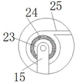
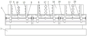
In the figure: 1. a base plate; 2. a drive motor; 3. a threaded shaft; 4. a threaded sleeve; 5. mounting blocks; 6. A first threaded rod; 7. a second threaded rod; 8. a nut; 9. a first bevel gear; 10. a short bar; 11. a second bevel gear; 12. a vertical plate; 13. a splint; 14. a mounting frame; 15. a long plate; 16. a jack plate; 17. A jack; 18. stainless steel pipe fittings; 19. a slide rod; 20. a sliding sleeve; 21. a chute; 22. a slider; 23. a wire winding rod; 24. a clockwork spring; 25. and (4) cloth strips.
Detailed Description
The technical solutions in the embodiments of the present invention will be described clearly and completely with reference to the accompanying drawings in the embodiments of the present invention, and it is obvious that the described embodiments are only some embodiments of the present invention, not all embodiments. Based on the embodiments in the present invention, all other embodiments obtained by a person skilled in the art without creative work belong to the protection scope of the present invention.
Referring to fig. 1-5, the present invention provides a straightening device for producing stainless steel pipe fittings for anastomat, which comprises: including bottom plate 1, its characterized in that: the upper surface of the bottom plate 1 is fixedly connected with a driving motor 2, the output end of the driving motor 2 is fixedly connected with a threaded rotating shaft 3, the outer surface of the threaded rotating shaft 3 is in threaded connection with a threaded sleeve 4, the upper surface of the threaded sleeve 4 is fixedly connected with a plurality of mounting blocks 5 which are hollow inside, the inner side walls of the mounting blocks 5 are rotatably connected with first threaded rods 6 through bearings, one ends of the first threaded rods 6 far away from the inner walls of the mounting blocks 5 are fixedly connected with second threaded rods 7, the outer surfaces of the first threaded rods 6 and the second threaded rods 7 are in threaded connection with nuts 8, the outer surface of the first threaded rods 6 is fixedly connected with first conical gears 9, short rods 10 are arranged on the outer surfaces of the mounting blocks 5 in an inserting mode, the mounting blocks 5 are rotatably connected with the short rods 10 through bearings, one ends of the short rods 10 are fixedly connected with second conical gears, the equal fixedly connected with riser 12 of upper surface of two nuts 8, one side that two risers 12 are relative all is provided with a plurality of splint 13, the last fixed surface of bottom plate 1 is connected with C shape mounting bracket 14, fixedly connected with rectangular plate 15 on the inside diapire of C shape mounting bracket 14, the surface of rectangular plate 15 rotates through the bearing and is connected with winding rod 23, the surface cover of winding rod 23 is equipped with clockwork spring 24, the surface winding of winding rod 23 has cloth 25, the other end of cloth 25 is connected with the surface fixed connection of installation piece 5, the equal fixedly connected with jack board 16 of upper surface of C shape mounting bracket 14, jack board 16's surface is provided with a plurality of jacks 17, the inside of jack 17 is provided with stainless steel pipe spare 18.
The supporting force is provided for the driving motor 2, the model number of the driving motor 2 is Y160M-4, and the peripheral circuit of the driving motor 2 adopts a common forward and reverse rotation circuit.
In order to move the two nuts 8 in the same direction or in opposite directions, in this embodiment, the first threaded rod 6 and the second threaded rod 7 are preferably of the same length and are of one-piece design, the threads of the first threaded rod 6 and the second threaded rod 7 being in opposite directions.
In order to enable the nut 8 to move stably in the horizontal direction, in the present embodiment, preferably, a slide rod 19 is fixedly connected between the inner walls of the mounting block 5, two sliding sleeves 20 are sleeved on the outer surface of the slide rod 19, and the outer surface of the sliding sleeve 20 is fixedly connected with the nut 8.
Play spacing effect, guarantee that thread bush 4 can stabilize the horizontal direction along spout 21 and remove, in this embodiment, preferred, spout 21 has been seted up to bottom plate 1's upper surface, and the inside sliding connection of spout 21 has slider 22, slider 22 and threaded sleeve 4 fixed connection.
For the effect of convenient use, in the present embodiment, preferably, a rotating disc is fixedly connected to one end of the short rod 10 far away from the second bevel gear 11.
The dust is prevented from entering the inside of the mounting block 5 through the gap between the long plate 15 and the mounting block 5, and in the embodiment, preferably, a leather sheath is fixedly connected between the outer surface of the long plate 15 and the inner wall of the mounting block 5.
A plurality of stainless steel pipes 18 can be processed simultaneously, in this embodiment, preferably, the number of the insertion holes 17 is nine, and the nine insertion holes are uniformly distributed on the outer surface of the insertion hole plate 16 and correspond to the clamping plate 13
The utility model discloses a theory of operation and use flow: when the straightening device is used, the stainless steel pipe 18 is inserted into the corresponding jack 17 according to the type, the short rod 10 is rotated through the arranged short rod 10, the short rod 10 drives the first threaded rod 6 and the second threaded rod 7 to synchronously rotate through the first bevel gear 9 and the second bevel gear 11, and the two nuts 8 drive the vertical plate 12 and the clamping plate 13 to relatively move due to opposite thread directions of the two threaded rods, so that the effect of clamping the stainless steel pipe 18 is achieved;
through the driving motor 2 who sets up, driving motor 2 drives the screw thread and changes 3 rotations, makes threaded sleeve 4 drive installation piece 5 and removes, and installation piece 5 drives stainless steel pipe fitting 18 through splint 13 and removes, passes through jack board 16 with it, and is corresponding rather than the model because of jack 17, and threaded sleeve 4 drives installation piece 5 and is rectilinear movement to reach the effect with stainless steel pipe fitting 18 aligning.
When the steel pipe fitting 18 is straightened and not repaired, the mounting block 5 pulls the cloth strip 25 to move, the cloth strip 25 is in a tightening state under the elastic action of the clockwork spring 24, and when the clamping of the clamping plate 13 is not firm, the phenomenon that the stainless steel pipe fitting 18 with the non-firm clamping falls and breaks is avoided, so that the safety of the device is improved.
Although embodiments of the present invention have been shown and described, it will be appreciated by those skilled in the art that changes, modifications, substitutions and alterations can be made in these embodiments without departing from the principles and spirit of the invention, the scope of which is defined in the appended claims and their equivalents.
Claims (9)
1. The utility model provides a straightener is used in production of stainless steel pipe fitting for anastomat, includes bottom plate (1), its characterized in that: the upper surface of the bottom plate (1) is fixedly connected with a driving motor (2), the output end of the driving motor (2) is fixedly connected with a threaded rotating shaft (3), the outer surface of the threaded rotating shaft (3) is in threaded connection with a threaded sleeve (4), the upper surface of the threaded sleeve (4) is fixedly connected with a plurality of mounting blocks (5) with hollow interiors, the inner side wall of each mounting block (5) is rotatably connected with a first threaded rod (6) through a bearing, one end, far away from the inner wall of each mounting block (5), of each first threaded rod (6) is fixedly connected with a second threaded rod (7), the outer surfaces of the first threaded rods (6) and the second threaded rods (7) are in threaded connection with nuts (8), the outer surface of each first threaded rod (6) is fixedly connected with a first bevel gear (9), and short rods (10) are arranged on the outer surface of each mounting block (5), the installation block (5) is connected with the short rod (10) in a rotating mode through a bearing, a second bevel gear (11) is fixedly connected to one end of the short rod (10), the second bevel gear (11) is meshed with the first bevel gear (9), two vertical plates (12) are fixedly connected to the upper surface of the nut (8), a plurality of clamping plates (13) are arranged on one side, opposite to the vertical plates (12), of the bottom plate (1), a C-shaped installation frame (14) is fixedly connected to the upper surface of the bottom plate, a long plate (15) is fixedly connected to the inner bottom wall of the C-shaped installation frame (14), a winding rod (23) is rotatably connected to the outer surface of the long plate (15) through a bearing, a clockwork spring (24) is sleeved on the outer surface of the winding rod (23), a cloth strip (25) is wound on the outer surface of the winding rod (23), and the other end of the cloth strip (25) is fixedly connected with the outer surface of the, the upper surface of the C-shaped mounting frame (14) is fixedly connected with a jack plate (16), a plurality of jacks (17) are arranged on the outer surface of the jack plate (16), and stainless steel pipe fittings (18) are arranged inside the jacks (17).
2. The straightening device for producing the stainless steel pipe fitting for the anastomat according to the claim 1, which is characterized in that: the upper surface of the bottom plate (1) is fixedly connected with a motor base, and the upper surface of the motor base is connected with the driving motor (2) through bolts.
3. The straightening device for producing the stainless steel pipe fitting for the anastomat according to the claim 1, which is characterized in that: the first threaded rod (6) and the second threaded rod (7) are the same in length and are designed in an integrated mode, and the thread directions of the first threaded rod (6) and the second threaded rod (7) are opposite.
4. The straightening device for producing the stainless steel pipe fitting for the anastomat according to the claim 1, which is characterized in that: fixedly connected with litter (19) between the inner wall of installation piece (5), the surface cover of litter (19) is equipped with two sliding sleeves (20), the surface of sliding sleeve (20) with nut (8) fixed connection.
5. The straightening device for producing the stainless steel pipe fitting for the anastomat according to the claim 1, which is characterized in that: the upper surface of the bottom plate (1) is provided with a sliding groove (21), the sliding groove (21) is connected with a sliding block (22) in a sliding mode, and the sliding block (22) is fixedly connected with the threaded sleeve (4).
6. The straightening device for producing the stainless steel pipe fitting for the anastomat according to the claim 1, which is characterized in that: one end of the short rod (10) far away from the second bevel gear (11) is fixedly connected with a rotary table.
7. The straightening device for producing the stainless steel pipe fitting for the anastomat according to the claim 1, which is characterized in that: a leather sleeve is fixedly connected between the outer surface of the long plate (15) and the inner wall of the mounting block (5).
8. The straightening device for producing the stainless steel pipe fitting for the anastomat according to the claim 1, which is characterized in that: the installation piece (5) quantity is three, and connects gradually, every the upper surface of long board (15) has threely splint (13), every splint (13) semicircular in shape, the directness of splint (13) that installation piece (5) correspond from a left side to the right side, increases gradually in proper order.
9. The straightening device for producing the stainless steel pipe fitting for the anastomat according to the claim 1, which is characterized in that: the number of the jacks (17) is nine, the jacks are uniformly distributed on the outer surface of the jack plate (16), and the jacks correspond to the clamping plates (13).
Priority Applications (1)
| Application Number | Priority Date | Filing Date | Title |
|---|---|---|---|
| CN202020380249.0U CN212264244U (en) | 2020-03-24 | 2020-03-24 | Straightening device for producing stainless steel pipe fitting for anastomat |
Applications Claiming Priority (1)
| Application Number | Priority Date | Filing Date | Title |
|---|---|---|---|
| CN202020380249.0U CN212264244U (en) | 2020-03-24 | 2020-03-24 | Straightening device for producing stainless steel pipe fitting for anastomat |
Publications (1)
| Publication Number | Publication Date |
|---|---|
| CN212264244U true CN212264244U (en) | 2021-01-01 |
Family
ID=73884398
Family Applications (1)
| Application Number | Title | Priority Date | Filing Date |
|---|---|---|---|
| CN202020380249.0U Active CN212264244U (en) | 2020-03-24 | 2020-03-24 | Straightening device for producing stainless steel pipe fitting for anastomat |
Country Status (1)
| Country | Link |
|---|---|
| CN (1) | CN212264244U (en) |
-
2020
- 2020-03-24 CN CN202020380249.0U patent/CN212264244U/en active Active
Similar Documents
| Publication | Publication Date | Title |
|---|---|---|
| CN215314831U (en) | Straightening mechanism for producing high-precision threaded stainless steel seamless steel pipe | |
| CN212264244U (en) | Straightening device for producing stainless steel pipe fitting for anastomat | |
| CN212070035U (en) | Aluminum product equipment of bending | |
| CN211052333U (en) | Pipe bending device convenient to carry | |
| CN210498106U (en) | Direction-adjustable straightening auxiliary device for wire harness processing | |
| CN109794656B (en) | Screw rod production and processing tapping machine | |
| CN209095399U (en) | Electronic component positioning device | |
| CN216442369U (en) | Machining clamp capable of improving roundness of die | |
| CN220880154U (en) | Aluminum alloy profile stamping device | |
| CN219358733U (en) | Positioning device for steel processing | |
| CN211615403U (en) | Hardware wrench | |
| CN210231101U (en) | Bending machine convenient to control bending angle | |
| CN210789014U (en) | Steel bar straightening machine | |
| CN208417828U (en) | Double-wall pipe guiding device | |
| CN220111979U (en) | Channel steel straightener | |
| CN214639961U (en) | Precise screw thread rolling die for pcb (printed circuit board) | |
| CN209121724U (en) | A kind of exhibit rack, display rack component connecting device | |
| CN213102113U (en) | A blending device for lubricating oil production | |
| CN219338637U (en) | Sponge cloth bonding press for underwear production | |
| CN214025459U (en) | Connecting device convenient to change electric drill batch head | |
| CN213990396U (en) | Direct-connected titanium pump connecting device | |
| CN220880052U (en) | Steel construction cold roll forming machine | |
| CN220592455U (en) | Metal processing sweeps clearance structure | |
| CN219900006U (en) | Spacing swager of air conditioner fin constructs | |
| CN214188040U (en) | Twisted tooth core-pulling mechanism |
Legal Events
| Date | Code | Title | Description |
|---|---|---|---|
| GR01 | Patent grant | ||
| GR01 | Patent grant |