CN212188127U - Improved rainwater purification device - Google Patents
Improved rainwater purification device Download PDFInfo
- Publication number
- CN212188127U CN212188127U CN202020556653.9U CN202020556653U CN212188127U CN 212188127 U CN212188127 U CN 212188127U CN 202020556653 U CN202020556653 U CN 202020556653U CN 212188127 U CN212188127 U CN 212188127U
- Authority
- CN
- China
- Prior art keywords
- box
- rainwater
- purification
- plate
- filter
- Prior art date
- Legal status (The legal status is an assumption and is not a legal conclusion. Google has not performed a legal analysis and makes no representation as to the accuracy of the status listed.)
- Expired - Fee Related
Links
Images

Landscapes
- Filtration Of Liquid (AREA)
Abstract
The utility model provides an improved generation rainwater purifier, including purifying box, guide tube, first backup pad, plugboard, the rainwater hole, connecting groove can filter rotatory purification frame structure, can float and promote box structure, socket and impurity collection box, guide tube bolted connection at the lower extreme intermediate position of purifying box. The utility model discloses the setting of first filter frame, rotor plate, first inlet opening, purifying box, guide pipe, rainwater hole and connecting groove is favorable to carrying out the rainwater primary purification work through first filter frame and first inlet opening and the filter screen inside the first inlet opening in the course of work, gets rid of impurity such as leaf weeds in the rainwater; the setting of falling L type connecting plate, the case connects the rope, promotes gasbag and hollow box is favorable to promoting the second at the in-process of work and crosses filter stand rebound, drives the right side rebound that first crosses filter stand, conveniently carries out the lift work at the in-process that purifies the rainwater.
Description
Technical Field
The utility model belongs to the technical field of the rainwater purifier, especially, relate to an improved generation rainwater purifier.
Background
Road runoff rainwater contains a large amount of pollutants, and pollutants carried by initial runoff rainwater are the most serious. The control of initial runoff is very critical for urban road rainwater utilization systems and runoff pollution control. Roads are the impermeable surfaces with the largest area in cities, and road runoff water is the main component of urban runoff water. Due to the deposit on the road surface, the garbage of pedestrians, the aging of the road surface, the waste gas discharged by vehicles, the abrasion of tires and the like, the pollution degree of the rainwater runoff on the road is higher than that of the rainwater runoff on other places such as roofs, greenbelts and the like, but the rainwater can carry a large amount of impurities in the flowing process and needs to be purified by a rainwater purification device.
But current rainwater purifier still has the in-process that carries out work and is inconvenient to carry out impurity cleaning work, and inconvenient in the in-process that purifies the rainwater to purifier carry out the lift work and inconvenient in the in-process that clears up impurity shelters from the inside problem of impurity entering water purification unit.
Therefore, it is necessary to invent an improved rainwater purification device.
SUMMERY OF THE UTILITY MODEL
In order to solve the technical problem, the utility model provides an improved generation rainwater purifier to there is the in-process inconvenient work of carrying out work that carries on in solving current rainwater purifier, inconvenient in the in-process that purifies the rainwater to purifier carry out the lift work and inconvenient in the in-process of clearance impurity shelters from the problem that impurity got into water purification unit inside. An improved rainwater purification device comprises a purification box, a guide pipe, a first support plate, an insertion plate, a rainwater hole, a connecting groove, a filterable rotary purification frame structure, a floatable push box structure, an insertion seat and an impurity collection box, wherein the guide pipe is connected to the middle position of the lower end of the purification box through a bolt; the first supporting plates are respectively welded at the four corners of the purifying box; the plugboards are respectively welded in the middle positions of the left side and the right side of the lower end of the first supporting plate; the rainwater hole is formed in the middle of the upper end of the purification box; the connecting grooves are respectively arranged in front of the left inner wall and behind the left inner wall of the rainwater hole; the filterable rotary purification frame structure is arranged inside the rainwater hole; the floatable push box structure is arranged at the lower end of the filterable rotary purification frame structure; the plug socket is connected to the middle position of the left side of the purifying box through a bolt; the impurity collecting box is inserted in the middle of the upper inner part of the inserting seat; the filterable rotary purification frame structure comprises a first filter frame, a rotating plate, a first water inlet hole, a lifting hole, a second support plate, a second filter frame and a second water inlet hole, wherein the rotating plate is welded on the front side and the back side of the left side of the first filter frame respectively; the first water inlet holes are sequentially formed in the first filter frame from left to right; the lifting hole is formed in the middle of the inner part of the right side of the first filter frame; the second supporting plate is welded on the rear side of the right side and the front side of the right side of the first filter frame respectively; the upper end of the second filter frame is connected to the right side of the lower end of the first filter frame through a bolt; and the second water inlet holes are sequentially arranged in the second filter frame from top to bottom.
Preferably, the floatable push box structure comprises an inverted L-shaped connecting plate, a storage box, a connecting rope, a push airbag and a hollow box, wherein the storage box is connected to the right side of the lower end of the inverted L-shaped connecting plate through a bolt; one end of the connecting rope is glued to the left side of the bottom end inside the storage box; the other end of the connecting rope is glued to the left side of the pushing air bag; the hollow box is connected with the lower end of the storage box through a bolt.
Preferably, the purification box is a rectangular stainless steel box; the purification box is communicated with the guide pipe; the lower end of the inserting plate is a conical stainless steel plate.
Preferably, the first filter frame and the second filter frame are respectively stainless steel frames; the rotating plate and the second supporting plate are respectively made of stainless steel plates.
Preferably, the rotating plates are respectively pivoted at the middle position inside the right side of the connecting groove; the first filter frame is inserted in the rainwater hole; the second supporting plates are respectively arranged on the right side of the upper end of the purifying box.
Preferably, the pushing air bag is a rubber bag filled with air; the storage box is a PVC box; the hollow box adopts a PPC box which is hollow inside and sealed.
Preferably, the inverted L-shaped connecting plate is connected to the lower end of the second filter frame through a bolt; the inverted L-shaped connecting plate, the storage box and the hollow box are arranged on the right side of the interior of the purifying box.
Compared with the prior art, the beneficial effects of the utility model are that:
1. the utility model discloses in, first filter frame, the rotor plate, first inlet opening, the purifying box, the guide pipe, rainwater hole and coupling groove's setting is favorable to carrying out the elementary purification work of rainwater through first filter frame and the inside filter screen of first inlet opening and first inlet opening at the in-process of work, gets rid of impurity such as leaf weeds in the rainwater.
2. The utility model discloses in, the type of falling L connecting plate, the case, connect the rope, promote the setting of gasbag and hollow box, be favorable to promoting the second at the in-process of work and filter the frame rebound, drive the right side rebound that first filtration put up, the convenient in-process that purifies the rainwater carries out the lift work.
3. The utility model discloses in, first filter frame, the rotor plate, first inlet opening, the setting of filter frame and second inlet opening is crossed to the second, is favorable to filtering the inside that frame and second inlet opening prevent that impurity in the rainwater from getting into the purifying box through the second in-process of work, conveniently carries out impurity and shelters from work.
4. The utility model discloses in, first filter frame, the rotor plate, the setting of first inlet opening and second backup pad is favorable to supporting first filter frame at the in-process of work, conveniently carries out the primary purification work of rainwater.
5. The utility model discloses in, purifying box, guide pipe, first backup pad, the setting in plugboard and rainwater hole is favorable to fixing purifying box when using, prevents to remove at the in-process purifying box that purifies the rainwater and influences the rainwater purification work.
6. The utility model discloses in, purifying box, the setting of box is collected to bayonet socket and impurity, be favorable to collecting impurity such as leaf, weeds through the box at the in-process that purifies the rainwater, conveniently carry out the impurity cleaning work.
Drawings
Fig. 1 is a schematic structural diagram of the present invention.
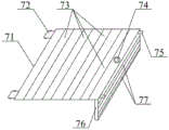
Fig. 2 is a schematic structural view of the filterable rotating purification frame structure of the present invention.
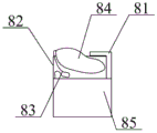
Fig. 3 is a schematic structural view of the floatable push box structure of the present invention.
In the figure:
1. a purification box; 2. a delivery pipe; 3. a first support plate; 4. a plugboard; 5. a rainwater hole; 6. a connecting groove; 7. a filterable rotary purification rack structure; 71. a first filter frame; 72. a rotating plate; 73. a first water inlet hole; 74. lifting and pulling the hole; 75. a second support plate; 76. a second filter frame; 77. a second water inlet hole; 8. a floatable push box structure; 81. an inverted L-shaped connecting plate; 82. a storage box; 83. connecting ropes; 84. pushing the air bag; 85. a hollow box; 9. a socket; 10. and an impurity collecting box.
Detailed Description
The utility model is described in detail with reference to the accompanying drawings, as shown in fig. 1 and fig. 2, an improved rainwater purification device comprises a purification box 1, a guiding and conveying pipe 2, a first support plate 3, an insertion plate 4, a rainwater hole 5, a connecting groove 6, a filterable rotary purification frame structure 7, a floatable push box structure 8, an insertion seat 9 and an impurity collecting box 10, wherein the guiding and conveying pipe 2 is connected with the middle position of the lower end of the purification box 1 through a bolt; the first supporting plates 3 are respectively welded at the four corners of the purifying box 1; the plugboard 4 is respectively welded at the middle positions of the left side and the right side of the lower end of the first supporting plate 3; the rainwater hole 5 is formed in the middle of the upper end of the purifying box 1; the connecting grooves 6 are respectively arranged in front of the left inner wall and behind the left inner wall of the rainwater hole 5; the filterable rotary purification frame structure 7 is arranged inside the rainwater hole 5; the floatable push box structure 8 is arranged at the lower end of the filterable rotary purification frame structure 7; the plug socket 9 is connected with the middle position of the left side of the purifying box 1 through a bolt; the impurity collecting box 10 is inserted in the middle of the upper inside of the inserting seat 9; the filterable rotary purification frame structure 7 comprises a first filter frame 71, a rotating plate 72, a first water inlet 73, a lifting hole 74, a second support plate 75, a second filter frame 76 and a second water inlet 77, wherein the rotating plate 72 is welded at the front and the back of the left side of the first filter frame 71 respectively; the first water inlet holes 73 are sequentially formed in the first filter frame 71 from left to right; the lifting hole 74 is arranged in the middle of the inner part of the right side of the first filter frame 71; the second supporting plate 75 is welded at the rear right side and the front right side of the first filter frame 71 respectively; the upper end of the second filter frame 76 is connected with the right side of the lower end of the first filter frame 71 through bolts; the second water inlet hole 77 is sequentially formed in the second filter frame 76 from top to bottom; when using, install purifying box 1 in suitable position, then use guide pipe 2 to connect rainwater collection equipment or treatment facility, make the rainwater get into purifying box 1's inside through the first inlet opening 73 that first filter bracket 71 upper end was seted up when purifying, impurity such as leaf weeds in the stainless steel net filtration rainwater through the inside setting of first inlet opening 73 purifies the work.
In this embodiment, referring to fig. 3, the floatable push box structure 8 includes an inverted L-shaped connection plate 81, a storage box 82, a connection rope 83, a push airbag 84 and a hollow box 85, wherein the storage box 82 is bolted to the right side of the lower end of the inverted L-shaped connection plate 81; one end of the connecting rope 83 is glued to the left side of the bottom end inside the storage box 82; the other end of the connecting rope 83 is glued to the left side of the pushing air bag 84; the hollow box 85 is connected with the lower end of the storage box 82 through bolts; the rainwater enters the inside of the purifying box 1 in the purifying process, then the air bag 84 and the hollow box 85 are pushed upwards by the buoyancy of the rainwater, and then the second filter frame 76 is pushed, so that the impurities at the upper end of the first filter frame 71 enter the inside of the impurity collecting box 10, and the rainwater is conveniently subjected to primary purifying work.
In this embodiment, specifically, the purification box 1 is a rectangular stainless steel box; the purifying box 1 is communicated with the guide pipe 2; the plugboard 4 is a stainless steel plate with a conical lower end.
In this embodiment, specifically, the first filter rack 71 and the second filter rack 76 are respectively made of stainless steel frames; the rotating plate 72 and the second supporting plate 75 are made of stainless steel plates, respectively.
In this embodiment, specifically, the rotating plates 72 are respectively coupled to the middle positions inside the right sides of the connecting grooves 6; the first filter frame 71 is inserted in the rainwater hole 5; the second supporting plates 75 are respectively disposed at the right side of the upper end of the purification box 1.
In this embodiment, specifically, the pushing air bag 84 is a rubber bag filled with air; the storage box 82 is a PVC box; the hollow box 85 is a PPC box which is hollow and sealed.
In this embodiment, specifically, the inverted L-shaped connecting plate 81 is bolted to the lower end of the second filter frame 76; the inverted-L-shaped connecting plate 81, the storage box 82, and the hollow box 85 are disposed on the right side of the inside of the purification box 1.
Principle of operation
The utility model discloses in, when using, install purifying box 1 in suitable position, then use guide pipe 2 to connect rainwater collection equipment or treatment facility, make the rainwater get into the inside of purifying box 1 through the first inlet opening 73 that first filter frame 71 upper end was seted up when purifying, impurity such as leaf weeds in the stainless steel net filtration rainwater that sets up through first inlet opening 73 is inside, carry out purification work, get into the inside of purifying box 1 through the rainwater at the in-process that purifies, then the buoyancy through the rainwater promotes promotion gasbag 84 and hollow box 85 upwards promotes, then promote second filter frame 76, make the impurity of first filter frame 71 upper end get into the inside that the box 10 was collected to impurity, the convenience is carried out primary purification work to the rainwater.
Utilize technical scheme, or technical personnel in the field are in the utility model discloses under technical scheme's the inspiration, design similar technical scheme, and reach above-mentioned technological effect, all fall into the utility model discloses a protection scope.
Claims (7)
1. An improved rainwater purification device is characterized by comprising a purification box (1), a guiding and conveying pipe (2), a first support plate (3), an insertion plate (4), a rainwater hole (5), a connecting groove (6), a filtering and rotating purification frame structure (7), a floatable push box structure (8), an insertion base (9) and an impurity collecting box (10), wherein the guiding pipe (2) is in bolted connection with the middle position of the lower end of the purification box (1); the first supporting plates (3) are respectively welded at the four corners of the purifying box (1); the plugboard (4) is respectively welded at the middle positions of the left side and the right side of the lower end of the first supporting plate (3); the rainwater hole (5) is formed in the middle of the upper end of the purifying box (1); the connecting grooves (6) are respectively arranged in front of the left inner wall and behind the left inner wall of the rainwater hole (5); the filterable rotary purification frame structure (7) is arranged inside the rainwater hole (5); the floatable push box structure (8) is arranged at the lower end of the filterable rotary purification frame structure (7); the plug socket (9) is connected to the middle position of the left side of the purifying box (1) through a bolt; the impurity collecting box (10) is inserted in the middle of the upper inner part of the inserting seat (9); the filterable rotary purification rack structure (7) comprises a first filter rack (71), a rotating plate (72), a first water inlet hole (73), a lifting hole (74), a second support plate (75), a second filter rack (76) and a second water inlet hole (77), wherein the rotating plate (72) is welded on the front side of the left side and the back side of the left side of the first filter rack (71) respectively; the first water inlet holes (73) are sequentially formed in the first filter frame (71) from left to right; the lifting hole (74) is formed in the middle of the inner part of the right side of the first filter frame (71); the second supporting plate (75) is respectively welded at the rear right side and the front right side of the first filter frame (71); the upper end of the second filter frame (76) is connected to the right side of the lower end of the first filter frame (71) through bolts; the second water inlet holes (77) are sequentially formed in the second filter rack (76) from top to bottom.
2. An improved rainwater purification device according to claim 1, wherein said floatable push box structure (8) comprises an inverted L-shaped connection plate (81), a storage box (82), a connection rope (83), a push airbag (84) and a hollow box (85), said storage box (82) is bolted to the right side of the lower end of the inverted L-shaped connection plate (81); one end of the connecting rope (83) is glued to the left side of the bottom end inside the storage box (82); the other end of the connecting rope (83) is glued to the left side of the pushing air bag (84); the hollow box (85) is connected with the lower end of the storage box (82) through bolts.
3. An improved rainwater purification device as defined in claim 1, characterized in that said purification box (1) is a rectangular parallelepiped stainless steel box; the purification box (1) is communicated with the guide pipe (2); the plugboard (4) adopts a stainless steel plate with the lower end set to be conical.
4. An improved rainwater purification device as defined in claim 1, wherein said first filtering rack (71) and said second filtering rack (76) are made of stainless steel frames; the rotating plate (72) and the second supporting plate (75) are respectively made of stainless steel plates.
5. An improved rainwater purification device as defined in claim 1, wherein said rotation plates (72) are respectively pivoted at the right inner middle position of the connection groove (6); the first filter frame (71) is inserted in the rainwater hole (5); the second supporting plates (75) are respectively arranged on the right side of the upper end of the purifying box (1).
6. An improved rainwater purification device as defined in claim 2, wherein said push air bag (84) is a rubber bag filled with gas; the storage box (82) is a PVC box; the hollow box (85) adopts a PPC box which is hollow inside and sealed.
7. An improved rainwater purification device as claimed in claim 2, wherein said inverted L-shaped connection plate (81) is bolted to the lower end of the second filter frame (76); the inverted L-shaped connecting plate (81), the storage box (82) and the hollow box (85) are arranged on the right side in the purifying box (1).
Priority Applications (1)
| Application Number | Priority Date | Filing Date | Title |
|---|---|---|---|
| CN202020556653.9U CN212188127U (en) | 2020-04-15 | 2020-04-15 | Improved rainwater purification device |
Applications Claiming Priority (1)
| Application Number | Priority Date | Filing Date | Title |
|---|---|---|---|
| CN202020556653.9U CN212188127U (en) | 2020-04-15 | 2020-04-15 | Improved rainwater purification device |
Publications (1)
| Publication Number | Publication Date |
|---|---|
| CN212188127U true CN212188127U (en) | 2020-12-22 |
Family
ID=73832794
Family Applications (1)
| Application Number | Title | Priority Date | Filing Date |
|---|---|---|---|
| CN202020556653.9U Expired - Fee Related CN212188127U (en) | 2020-04-15 | 2020-04-15 | Improved rainwater purification device |
Country Status (1)
| Country | Link |
|---|---|
| CN (1) | CN212188127U (en) |
-
2020
- 2020-04-15 CN CN202020556653.9U patent/CN212188127U/en not_active Expired - Fee Related
Similar Documents
| Publication | Publication Date | Title |
|---|---|---|
| CN205975797U (en) | Rainwater collecting and processing device | |
| CN208327621U (en) | A kind of sewage treatment ozone air-float device | |
| CN113443727B (en) | Sludge and wastewater filter-pressing treatment device for car washing tank | |
| CN212188127U (en) | Improved rainwater purification device | |
| CN112299601A (en) | Organic wastewater and sewage treatment equipment and sewage treatment method | |
| CN216023495U (en) | Urban rainfall flood wastewater treatment device | |
| CN215388017U (en) | Municipal administration sewage treatment device | |
| CN214714994U (en) | Ecological purifier of drinking water source ground bypass | |
| CN205216391U (en) | Mobile sewage treatment device | |
| CN205936766U (en) | Automobile emission purification device | |
| CN214319557U (en) | High-efficient ultrasonic dust collector | |
| CN209957489U (en) | Lifting type rainwater and sewage tail end ecological treatment device | |
| CN204824436U (en) | High -efficient advanced wastewater treatment complete set is made up and is put | |
| CN209011201U (en) | A kind of rainwater recycle reuse means | |
| CN106895514A (en) | A kind of air purifier | |
| CN207227174U (en) | Integrated apparatus is collected in a kind of sliding back of the body formula dmp filter purification | |
| CN207356928U (en) | Modular electrical minor dedusting and purifying device | |
| CN209957488U (en) | Terminal ecological treatment device of rain sewage | |
| CN217202442U (en) | Industrial sewage microbial degradation device fast in installation | |
| CN212198777U (en) | Rural domestic sewage treatment device | |
| CN219033381U (en) | Rainwater collection and utilization device for green road construction | |
| CN220432379U (en) | Sewage treatment purifying mechanism of hydraulic engineering | |
| CN220223871U (en) | Domestic sewage denitrification treatment device | |
| CN212984103U (en) | But one-level highway curb drainage device of recycle water resource | |
| CN213834742U (en) | Energy-saving purifier for sewage treatment |
Legal Events
| Date | Code | Title | Description |
|---|---|---|---|
| GR01 | Patent grant | ||
| GR01 | Patent grant | ||
| CF01 | Termination of patent right due to non-payment of annual fee |
Granted publication date: 20201222 |
|
| CF01 | Termination of patent right due to non-payment of annual fee |