CN212174618U - Industrial waste water filters recovery unit - Google Patents
Industrial waste water filters recovery unit Download PDFInfo
- Publication number
- CN212174618U CN212174618U CN202020424080.4U CN202020424080U CN212174618U CN 212174618 U CN212174618 U CN 212174618U CN 202020424080 U CN202020424080 U CN 202020424080U CN 212174618 U CN212174618 U CN 212174618U
- Authority
- CN
- China
- Prior art keywords
- box body
- baffle
- filter screen
- fixedly connected
- box
- Prior art date
- Legal status (The legal status is an assumption and is not a legal conclusion. Google has not performed a legal analysis and makes no representation as to the accuracy of the status listed.)
- Active
Links
Images

Abstract
The utility model discloses an industrial wastewater filtering and recycling device in the technical field of wastewater filtering and recycling, which comprises a box body, wherein a motor and a charging pipe are arranged at one side of the outer surface at the upper end of the box body, the motor is arranged at one side of the charging pipe, a connecting block is movably connected at the middle position at the upper end of the box body, a filter screen is fixedly connected at the outer surface at the lower end of the connecting block, a limiting block is fixedly connected at the lower end of the filter screen, a stirring shaft is arranged in the box body, blades are arranged at the outer surface of the stirring shaft, the upper end and the lower end of the outer surface of the stirring shaft are movably connected with the box body, a baffle is fixedly connected at one side of the inner part of the box body, and a baffle is fixedly connected at the outer surface at the lower end of the box body, the efficiency of sewage treatment recycle is improved.
Description
Technical Field
The utility model relates to a waste water filters recovery technical field, specifically is an industrial waste water filters recovery unit.
Background
In the wastewater treatment, the wastewater is treated by physical, chemical and biological methods, so that the wastewater is purified, the pollution is reduced, the wastewater is recycled and reused, and the water resource is fully utilized.
For example, chinese patent application No. CN201920482004.6 is a wastewater filtering and recycling device, which comprises the following components: during the use, start driving motor to throw in sewage and purifying agent simultaneously in to the rose box, sewage falls to the bottom of rose box with the purifying agent together after the filtration of filter screen, and driving motor can drive dwang and puddler when starting, in time cleans solid-state impurity on the filter screen, improves filtration efficiency, and waste water and purifying agent that the device also can filter simultaneously mix the stirring, improve waste water treatment recovery efficiency.
This kind of waste water filters recovery unit can not give the sufficient settling time of sewage for the impurity precipitation effect of sewage is good enough, has consequently increased the burden among the subsequent sewage treatment process, can't effectively improve sewage filtration efficiency, and based on this, the utility model designs an industrial waste water filters recovery unit in order to solve above-mentioned problem.
SUMMERY OF THE UTILITY MODEL
An object of the utility model is to provide an industrial waste water filters recovery unit to the settling time that can not give sewage is enough that proposes in solving above-mentioned background art, makes the impurity precipitation effect of sewage good inadequately, has consequently increased the problem of burden among the subsequent sewage treatment process.
In order to achieve the above object, the utility model provides a following technical scheme: an industrial wastewater filtering and recycling device comprises a box body, wherein a motor and a feed pipe are arranged on one side of the outer surface of the upper end of the box body, the motor is positioned on one side of the feed pipe, a connecting block is movably connected to the middle position of the upper end of the box body, a filter screen is fixedly connected to the outer surface of the lower end of the connecting block, a limiting block is fixedly connected to the lower end of the filter screen, a stirring shaft is arranged in the box body, blades are arranged on the outer surface of the stirring shaft, the upper end and the lower end of the outer surface of the stirring shaft are movably connected with the box body, a baffle is fixedly connected to one side of the inner part of the box body, a baffle plate is fixedly connected to the outer surface of the lower end of the box body, a connecting shaft penetrates through the inner, and a sewage discharge pipe is arranged below the water inlet pipe, and a filter screen is arranged on the outer surface of the other side of the box body.
Preferably, the direction fan fixed connection is at the surface of connecting axle, the one end of connecting axle is provided with the motor, a plurality of all be parallel arrangement between the baffle.
Preferably, the outer surface of the lower end of the box body is fixedly connected with a collecting box, and the collecting box is positioned on one side of the filter screen.
Preferably, the baffle is located one side of inlet tube, and the baffle is the slope setting.
Preferably, the filter screen is located the inside upper end position of box, stopper swing joint is in the inside of box.
Compared with the prior art, the beneficial effects of the utility model are that:
1. the sewage can be approximately statically precipitated in the cavity at one side of the box body, and can flow into the cavity at the other side in the box body through the filter screen when reaching the height of the filter screen, so that the sewage can be precipitated for a long time, the sewage treatment effect is ensured, the connecting block is connected with the box body through screws, a worker can regularly take out and clean the filter screen, the stability of mounting the filter screen can be ensured under the action of the limiting block, the baffle can introduce the sewage discharged in real time into the box body, the newly discharged sewage is effectively prevented from directly entering the cavity at the other side of the box body through the filter screen, and a better guiding effect is achieved;
2. the impurity that deposits can deposit in the inside of box, the staff can regularly clear up bottom half, starter motor drives the connecting axle and the direction fan rotates, the direction fan can be stirred bottom half's impurity to blow off pipe department discharge, better effect of shifting impurity has, the bottom excessive deposit that can not make impurity accumulation heap is inside the box, better cleaning action has, can effectual reduction under the effect of baffle because rivers flow the condition of raising impurity here, the effect that sewage impurity deposits has been guaranteed, better impurity fixity has, make sewage treatment's effect better, the efficiency of sewage treatment recycle has been improved, and convenient to use.
Of course, it is not necessary for any particular product to achieve all of the above-described advantages at the same time.
Drawings
In order to more clearly illustrate the technical solutions of the embodiments of the present invention, the drawings used in the description of the embodiments will be briefly introduced below, and it is obvious that the drawings in the following description are only some embodiments of the present invention, and it is obvious for those skilled in the art that other drawings can be obtained according to these drawings without creative efforts.
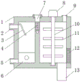
FIG. 1 is a schematic view of the overall structure of the present invention;
FIG. 2 is a combined view of the filter screen and the connecting block of the present invention;
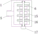
FIG. 3 is a combined view of the sewage draining pipe and the partition board of the present invention;
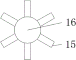
fig. 4 is a combined view of the guiding fan and the connecting shaft of the present invention.
In the drawings, the components represented by the respective reference numerals are listed below:
1. a box body; 2. a water inlet pipe; 3. a baffle plate; 4. a filter screen; 5. a blow-off pipe; 6. a partition plate; 7. connecting blocks; 8. a motor; 9. a feed tube; 10. a stirring shaft; 11. a blade; 12. filtering with a screen; 13. a collection box; 14. a limiting block; 15. a guide fan; 16. a connecting shaft; 17. an electric motor.
Detailed Description
The technical solutions in the embodiments of the present invention will be described clearly and completely with reference to the accompanying drawings in the embodiments of the present invention, and it is obvious that the described embodiments are only some embodiments of the present invention, not all embodiments. Based on the embodiments of the present invention, all other embodiments obtained by a person of ordinary skill in the art without creative efforts belong to the protection scope of the present invention.
Referring to fig. 1 to 4, the present invention provides a technical solution of an industrial wastewater filtering and recycling device: an industrial wastewater filtering and recycling device comprises a box body 1, wherein a motor 8 and a feed pipe 9 are arranged at one side of the outer surface of the upper end of the box body 1, the motor 8 is positioned at one side of the feed pipe 9, a connecting block 7 is movably connected at the middle position of the upper end of the box body 1, a filter screen 4 is fixedly connected at the outer surface of the lower end of the connecting block 7, a limiting block 14 is fixedly connected at the lower end of the filter screen 4, a stirring shaft 10 is arranged inside the box body 1, blades 11 are arranged on the outer surface of the stirring shaft 10, the upper end and the lower end of the outer surface of the stirring shaft 10 are movably connected with the box body 1, a baffle 3 is fixedly connected at one side of the inner position of the box body 1, a baffle 6 is fixedly connected at the outer surface of the lower end of the box body 1, a connecting shaft 16 penetrates through, the utility model discloses a sewage treatment device, including box 1, connecting axle 16, baffle 3, and baffle 3, one side surface of box 1 is provided with inlet tube 2, and the below of inlet tube 2 is provided with blow off pipe 5, the opposite side surface of box 1 is provided with filter screen 12, 15 fixed connection of direction fan are at the surface of connecting axle 16, the one end of connecting axle 16 is provided with motor 17, a plurality of all be parallel arrangement between the baffle 6, the outer fixed surface of lower extreme of box 1 is connected with collecting box 13, and collecting box 13 is located one side of filter screen 12, baffle 3 is located one side of inlet tube 2, and baffle 3 is the slope setting, filter screen 4 is located the inside upper end position of box 1, 14.
One specific application of this embodiment is: the working personnel can connect the motor 8 and the motor 17 with an external power supply, sewage is discharged through the water inlet pipe 2, the sewage can be close to static sedimentation in a cavity on one side of the box body 1, when the sewage reaches the height of the filter screen 4, the sewage can flow into a cavity on the other side in the box body 1 through the filter screen 4, the connecting block 7 is connected with the box body 1 through a screw, the working personnel can regularly take out the filter screen 4 for cleaning, the stability of installing the filter screen 4 can be ensured under the action of the limiting block 14, the motor 8 drives the stirring shaft 10 and the blade 11 to rotate, further sewage in the other cavity can be stirred, a purifying agent is added through the feeding pipe 9, the sewage can be further treated, then the sewage is discharged out of the box body 1 through the filter screen 12, part of impurities which can not pass through the filter screen 12 can fall into the collecting box 13, and the bottom of the collecting, when sewage is discharged into the box body 1, the baffle 3 can introduce the sewage which is discharged in real time into the box body 1, the sewage which is newly discharged is effectively prevented from directly entering a cavity at the other side of the box body 1 through the filter screen 4, precipitated impurities can be deposited in the box body 1, a worker can clean the bottom of the box body 1 at regular time, the starting motor 17 drives the connecting shaft 16 and the guide fan 15 to rotate, the guide fan 15 can stir the impurities at the bottom of the box body 1 to the blow-off pipe 5 to be discharged, the effect of better transferring the impurities is achieved, the bottom of an impurity accumulation pile is not excessively deposited in the box body 1, the cleaning effect is better, the condition that the impurities are raised due to water flow can be effectively reduced under the effect of the baffle 6, the effect of precipitating the sewage impurities is ensured, the impurity fixing performance is better, and the sewage treatment effect is better, the efficiency of sewage treatment recycle is improved, the model of the motor 8 is Y112M, and the model of the motor 17 is XD-3420-2.
The utility model discloses the use of mutually supporting between the water purifying agent and relation of connection all adopt the utility model provides a background data is given, and cooperate the utility model discloses a description of specification, the technical field personnel that belong to can reach its use to obtain corresponding result of use, the event does not have the one-to-one and discloses.
The utility model provides a product model is only for the use that this technical scheme goes on according to the structural feature of product, and its product can be adjusted and reform transform after purchasing, makes it match more and accord with the utility model belongs to technical scheme, it is the technical scheme of an optimal application of this technical scheme, and the model of its product can be replaced and reform transform according to the technical parameter of its needs, and it is familiar for technical staff that belongs to in the field, consequently, what technical staff that belongs to in the field can be clear passes through the utility model provides a technical scheme obtains corresponding result of use.
In the description herein, references to the description of "one embodiment," "an example," "a specific example," etc., mean that a particular feature, structure, material, or characteristic described in connection with the embodiment or example is included in at least one embodiment or example of the invention. In this specification, the schematic representations of the terms used above do not necessarily refer to the same embodiment or example. Furthermore, the particular features, structures, materials, or characteristics described may be combined in any suitable manner in any one or more embodiments or examples.
The preferred embodiments of the present invention disclosed above are intended only to help illustrate the present invention. The preferred embodiments are not intended to be exhaustive or to limit the invention to the precise embodiments disclosed. Obviously, many modifications and variations are possible in light of the above teaching. The embodiments were chosen and described in order to best explain the principles of the invention and its practical applications, to thereby enable others skilled in the art to best understand the invention for and utilize the invention. The present invention is limited only by the claims and their full scope and equivalents.
Claims (5)
1. The utility model provides an industrial waste water filters recovery unit, includes box (1), its characterized in that: the automatic feeding device is characterized in that a motor (8) and a feeding pipe (9) are arranged on one side of the outer surface of the upper end of the box body (1), the motor (8) is located on one side of the feeding pipe (9), a connecting block (7) is movably connected to the middle position of the upper end of the box body (1), a filter screen (4) is fixedly connected to the outer surface of the lower end of the connecting block (7), a limiting block (14) is fixedly connected to the lower end of the filter screen (4), a stirring shaft (10) is arranged inside the box body (1), blades (11) are arranged on the outer surface of the stirring shaft (10), the upper end and the lower end of the outer surface of the stirring shaft (10) are movably connected with the box body (1), a baffle (3) is fixedly connected to one side of the inside of the box body (1), a baffle (6) is fixedly connected, the quantity of baffle (6) is a plurality of, two be provided with direction fan (15) between baffle (6), one side surface of box (1) is provided with inlet tube (2), and the below of inlet tube (2) is provided with blow off pipe (5), the opposite side surface of box (1) is provided with filter screen (12).
2. The industrial wastewater filtering and recycling device according to claim 1, wherein: the direction fan (15) fixed connection is in the surface of connecting axle (16), the one end of connecting axle (16) is provided with motor (17), a plurality of all be parallel arrangement between baffle (6).
3. The industrial wastewater filtering and recycling device according to claim 1, wherein: the outer surface of the lower end of the box body (1) is fixedly connected with a collecting box (13), and the collecting box (13) is positioned on one side of the filter screen (12).
4. The industrial wastewater filtering and recycling device according to claim 1, wherein: the baffle (3) is positioned on one side of the water inlet pipe (2), and the baffle (3) is obliquely arranged.
5. The industrial wastewater filtering and recycling device according to claim 1, wherein: the filter screen (4) is positioned at the upper end of the interior of the box body (1), and the limiting block (14) is movably connected to the interior of the box body (1).
Priority Applications (1)
| Application Number | Priority Date | Filing Date | Title |
|---|---|---|---|
| CN202020424080.4U CN212174618U (en) | 2020-03-30 | 2020-03-30 | Industrial waste water filters recovery unit |
Applications Claiming Priority (1)
| Application Number | Priority Date | Filing Date | Title |
|---|---|---|---|
| CN202020424080.4U CN212174618U (en) | 2020-03-30 | 2020-03-30 | Industrial waste water filters recovery unit |
Publications (1)
| Publication Number | Publication Date |
|---|---|
| CN212174618U true CN212174618U (en) | 2020-12-18 |
Family
ID=73772218
Family Applications (1)
| Application Number | Title | Priority Date | Filing Date |
|---|---|---|---|
| CN202020424080.4U Active CN212174618U (en) | 2020-03-30 | 2020-03-30 | Industrial waste water filters recovery unit |
Country Status (1)
| Country | Link |
|---|---|
| CN (1) | CN212174618U (en) |
-
2020
- 2020-03-30 CN CN202020424080.4U patent/CN212174618U/en active Active
Similar Documents
| Publication | Publication Date | Title |
|---|---|---|
| CN211283995U (en) | Purification sedimentation tank for environmental protection engineering sewage treatment | |
| CN210915467U (en) | Municipal administration sewage recovery processing apparatus | |
| CN214087990U (en) | Waste water treatment device based on papermaking processing usefulness | |
| CN213569989U (en) | Sewage treatment equipment for steel plant | |
| CN210505855U (en) | Towards version hydrologic cycle filter equipment | |
| CN212174618U (en) | Industrial waste water filters recovery unit | |
| CN211896388U (en) | Novel industrial sewage treatment device | |
| CN208049553U (en) | A kind of filter device of connection municipal sewers | |
| CN210796042U (en) | Wash a pigment waste water impurity filter equipment | |
| CN212356920U (en) | Industrial sewage treatment device | |
| CN216549942U (en) | Filter for sewage precipitation treatment | |
| CN220335018U (en) | Papermaking wastewater zero discharge system | |
| CN219689441U (en) | Electrochemical water treatment device with filtering function | |
| CN218145995U (en) | Efficient sewage flocculation clarification device | |
| CN220467689U (en) | Sewage treatment's filter equipment | |
| CN218910093U (en) | Water quality purifying device | |
| CN217780926U (en) | Domestic sewage treatment device | |
| CN219341869U (en) | Water purifier capable of collecting impurities | |
| CN218709272U (en) | Water treatment device for refuse dump | |
| CN217794871U (en) | Domestic sewage filtering and collecting device | |
| CN220070849U (en) | Papermaking sewage purification equipment | |
| CN220537514U (en) | Filter equipment of industrial wastewater purification device | |
| CN219384929U (en) | Sewage water circulation treatment equipment | |
| CN219526382U (en) | Integrated SMBR sewage treatment equipment | |
| CN214158632U (en) | Sedimentation tank for sludge treatment with high sedimentation rate |
Legal Events
| Date | Code | Title | Description |
|---|---|---|---|
| GR01 | Patent grant | ||
| GR01 | Patent grant |