CN212166340U - Ultrasound Therapy Equipment - Google Patents
Ultrasound Therapy Equipment Download PDFInfo
- Publication number
- CN212166340U CN212166340U CN201790001581.8U CN201790001581U CN212166340U CN 212166340 U CN212166340 U CN 212166340U CN 201790001581 U CN201790001581 U CN 201790001581U CN 212166340 U CN212166340 U CN 212166340U
- Authority
- CN
- China
- Prior art keywords
- transducer
- guide
- ultrasonic
- ultrasonic treatment
- window
- Prior art date
- Legal status (The legal status is an assumption and is not a legal conclusion. Google has not performed a legal analysis and makes no representation as to the accuracy of the status listed.)
- Active
Links
Images


Classifications
-
- A—HUMAN NECESSITIES
- A61—MEDICAL OR VETERINARY SCIENCE; HYGIENE
- A61N—ELECTROTHERAPY; MAGNETOTHERAPY; RADIATION THERAPY; ULTRASOUND THERAPY
- A61N7/00—Ultrasound therapy
- A61N7/02—Localised ultrasound hyperthermia
-
- A—HUMAN NECESSITIES
- A61—MEDICAL OR VETERINARY SCIENCE; HYGIENE
- A61N—ELECTROTHERAPY; MAGNETOTHERAPY; RADIATION THERAPY; ULTRASOUND THERAPY
- A61N7/00—Ultrasound therapy
- A61N2007/0082—Scanning transducers
-
- A—HUMAN NECESSITIES
- A61—MEDICAL OR VETERINARY SCIENCE; HYGIENE
- A61N—ELECTROTHERAPY; MAGNETOTHERAPY; RADIATION THERAPY; ULTRASOUND THERAPY
- A61N7/00—Ultrasound therapy
- A61N2007/0086—Beam steering
- A61N2007/0091—Beam steering with moving parts, e.g. transducers, lenses, reflectors
-
- A—HUMAN NECESSITIES
- A61—MEDICAL OR VETERINARY SCIENCE; HYGIENE
- A61N—ELECTROTHERAPY; MAGNETOTHERAPY; RADIATION THERAPY; ULTRASOUND THERAPY
- A61N7/00—Ultrasound therapy
Landscapes
- Health & Medical Sciences (AREA)
- Engineering & Computer Science (AREA)
- Biomedical Technology (AREA)
- Nuclear Medicine, Radiotherapy & Molecular Imaging (AREA)
- Radiology & Medical Imaging (AREA)
- Life Sciences & Earth Sciences (AREA)
- Animal Behavior & Ethology (AREA)
- General Health & Medical Sciences (AREA)
- Public Health (AREA)
- Veterinary Medicine (AREA)
- Surgical Instruments (AREA)
Abstract
本实用新型涉及一种超声波外科设备,其中,盒包括填充有介质的内部空白空间的盒外壳;可移动地设置于所述盒外壳的内部并包括用于产生聚焦超声波的换能器的超声波治疗部;使由所述换能器产生的超声波从其穿过的窗口;以及使所述超声波治疗部在所述盒外壳内部移动的驱动部,其中,当所述换能器向一方向移动时,从所述窗口至所述换能器之间的隔开距离被重复地增大和减小。
This utility model relates to an ultrasonic surgical device, wherein the device includes a housing comprising an outer shell filled with an internal blank space of a medium; an ultrasonic therapy unit movably disposed inside the housing and including a transducer for generating focused ultrasonic waves; a window through which the ultrasonic waves generated by the transducer pass; and a drive unit for moving the ultrasonic therapy unit inside the housing, wherein, when the transducer moves in one direction, the distance between the window and the transducer is repeatedly increased and decreased.
Description
技术领域technical field
本实用新型的一实施例涉及一种超声波治疗设备。An embodiment of the present invention relates to an ultrasonic therapy device.
背景技术Background technique
目前正在开发改善皮肤弹性、减少皱纹等改善皮肤状态的治疗技术或减少皮下脂肪的各种治疗技术。这种治疗技术大致分为侵入性方法和非侵入性方法,并且提供了超声波治疗设备,该治疗设备能够将强聚焦超声波(Intensity focused ultrasound:IFU)照射于皮肤内部后在规定的肌肉或脂肪层等组织形成热焦点,从而再生或移除组织的方式而进行治疗。Currently, various treatments are being developed to improve skin condition, such as improving skin elasticity and reducing wrinkles, or to reduce subcutaneous fat. This treatment technique is roughly classified into an invasive method and a non-invasive method, and provides an ultrasonic treatment device capable of irradiating the inside of the skin with Intensity Focused Ultrasound (IFU) in a prescribed muscle or fat layer. Treatment is done by waiting for the tissue to form a thermal focus, thereby regenerating or removing the tissue.
实用新型内容Utility model content
技术问题technical problem
根据本实用新型的一实施例,可以提供一种超声波治疗设备,其特征在于,利用超声波提高治疗技术的效率性和稳定性。According to an embodiment of the present invention, an ultrasonic treatment device can be provided, which is characterized in that the efficiency and stability of the treatment technique are improved by using ultrasonic waves.
技术方案Technical solutions
根据本实用新型涉及一种超声波治疗设备,其特征在于,包括盒,所述盒包括填充于内部空白空间填充有介质的盒外壳;可移动地设置于所述盒外壳的内部并包括用于产生聚焦超声波的换能器的超声波治疗部;使在所述换能器产生的超声波穿过的窗口;以及使所述超声波治疗部在所述盒外壳内部移动的驱动部,其中,当所述换能器向一方向移动时,从所述窗口至所述换能器之间的隔开距离被重复地增大和减小。The utility model relates to an ultrasonic therapy device, which is characterized in that it includes a box, and the box includes a box shell filled with a medium in the inner empty space; an ultrasonic treatment part of a transducer that focuses ultrasonic waves; a window through which ultrasonic waves generated in the transducer pass; and a drive part that moves the ultrasonic treatment part inside the cartridge case, wherein when the replacement As the transducer moves in one direction, the separation distance from the window to the transducer is repeatedly increased and decreased.
可选地,所述驱动部形成为圆柱形并且包括偏心驱动凸轮,所述偏心驱动凸轮的旋转轴与所述圆柱形的中心轴被隔开;所述超声波治疗部包括连杆和连接器,所述连杆的一侧结合于偏心驱动凸轮外面的一侧并且所述连杆的另一侧结合于所述连接器,所述换能器可以随着所述偏心驱动凸轮的旋转而移动。Optionally, the driving part is formed in a cylindrical shape and includes an eccentric driving cam, and the rotation axis of the eccentric driving cam is spaced apart from the central axis of the cylindrical shape; the ultrasonic treatment part includes a connecting rod and a connector, One side of the link is coupled to a side outside the eccentric drive cam and the other side of the link is coupled to the connector, and the transducer can move as the eccentric drive cam rotates.
可选地,所述一方向是从所述盒外壳的一端向另一端的方向,并且若所述偏心驱动凸轮顺时针旋转,则所述换能器向所述一方向移动;若所述偏心驱动凸轮沿逆时针方向旋转,则所述换能器从盒外壳另一端向一端的方向移动,从所述窗口至所述换能器之间的隔开距离可以被重复地增大和减小。Optionally, the one direction is a direction from one end of the box shell to the other end, and if the eccentric drive cam rotates clockwise, the transducer moves in the one direction; if the eccentric drive cam rotates clockwise When the driving cam rotates in a counterclockwise direction, the transducer moves from the other end of the cartridge housing to one end, and the separation distance from the window to the transducer can be repeatedly increased and decreased.
可选地,所述超声波治疗设备还包括引导臂,所述引导臂在所述换能器的下部所指向的方向相对于所述窗口保持恒定时引导所述超声波治疗部向前运动、向后运动、上升和下降,所述连杆可旋转地结合于所述连接器,并且所述连接器通过引导臂的接触面被支撑的同时可以上升或下降。Optionally, the ultrasonic treatment device further includes a guide arm that guides the ultrasonic treatment part to move forward and backward when the direction in which the lower part of the transducer points is kept constant relative to the window. Moving, ascending and descending, the link is rotatably coupled to the connector, and the connector can ascend or descend while being supported by the contact surface of the guide arm.
可选地,所述超声波治疗设备还包括引导臂,所述引导臂在所述换能器的下部所指向的方向相对于所述窗口保持恒定时引导所述超声波治疗部向前运动、向后运动、上升和下降;所述设备还设置向所述换能器上方向突出的导针,并且在所述引导臂还设置收容所述导针的导针孔,当所述导针被支撑于导向针孔的内壁时所述换能器上升或下降,从而所述换能器的下部所指向的方向可以相对于所述窗口保持恒定。Optionally, the ultrasonic treatment device further includes a guide arm that guides the ultrasonic treatment part to move forward and backward when the direction in which the lower part of the transducer points is kept constant relative to the window. The device is also provided with a guide needle protruding toward the upper direction of the transducer, and the guide arm is also provided with a guide needle hole for accommodating the guide needle, when the guide needle is supported on the The transducer is raised or lowered while being guided to the inner wall of the pinhole, so that the direction in which the lower part of the transducer points can be kept constant relative to the window.
可选地,所述超声波治疗设备还包括引导臂,所述引导臂在所述换能器的下部所指向的方向相对于所述窗口保持恒定时引导所述超声波治疗部向前运动、向后运动、上升和下降;当所述连接器通过与引导臂的接触面而被支撑时所述连接器上升或下降,并且在所述引导臂处还设置收容导针的导针孔,当所述导针被支撑于导向针孔的内壁时所述换能器上升或下降,从而所述换能器的下部所指向的方向可以相对于所述窗口保持恒定。Optionally, the ultrasonic treatment device further includes a guide arm that guides the ultrasonic treatment part to move forward and backward when the direction in which the lower part of the transducer points is kept constant relative to the window. Movement, rise and fall; when the connector is supported by the contact surface with the guide arm, the connector rises or falls, and a guide pin hole for accommodating a guide pin is also provided at the guide arm. The transducer is raised or lowered when the guide pin is supported on the inner wall of the guide pin hole, so that the direction in which the lower part of the transducer points can be kept constant relative to the window.
可选地,所述超声波治疗设备还包括设置于所述盒外壳内部且与偏心驱动凸轮平行的引导轨,并且当所述引导臂被支撑于所述引导轨时所述引导臂前进或后退。Optionally, the ultrasonic treatment apparatus further includes a guide rail disposed inside the cassette housing and parallel to the eccentric drive cam, and the guide arm advances or retreats when the guide arm is supported on the guide rail.
可选地,所述偏心驱动凸轮包括:由金属制成的轴;由合成树脂材料制成的形成圆柱形的主体部,并且所述偏心驱动凸轮的旋转轴是所述主体部的中心轴。Optionally, the eccentric drive cam includes: a shaft made of metal; a main body part made of a synthetic resin material forming a cylindrical shape, and the rotation axis of the eccentric drive cam is a central axis of the main body part.
可选地,所述连杆的一侧形成包裹偏心驱动凸轮的环形。Optionally, one side of the connecting rod forms an annular shape wrapping the eccentric drive cam.
可选地,所述驱动部包括:结合于所述盒外壳内部的可旋转的驱动凸轮;以及沿所述驱动凸轮的外周面设置的第一凹槽;所述超声波治疗部包括:固定于所述换能器的引导部;以及一端沿第一凹槽可移动地插入于所述第一凹槽并且另一端固定于所述换能器或所述引导部的插入针,其中,在所述插入针和所述第一凹槽的接触点中,到所述驱动凸轮的旋转轴距离最短的第一接触点随着所述驱动凸轮的旋转而移动,从所述驱动凸轮的旋转轴到第一接触点的距离可以增大或减小。Optionally, the driving part comprises: a rotatable driving cam coupled to the inside of the box shell; and a first groove provided along the outer peripheral surface of the driving cam; the ultrasonic treatment part comprises: fixed on the a guide part of the transducer; and an insertion needle whose one end is movably inserted into the first groove along the first groove and the other end is fixed to the transducer or the guide part, wherein in the Among the contact points of the insertion needle and the first groove, the first contact point with the shortest distance to the rotation axis of the drive cam moves with the rotation of the drive cam, from the rotation axis of the drive cam to the first contact point. The distance of a contact point can be increased or decreased.
可选地,所述超声波治疗设备还包括当所述插入针向第一凹槽的方向被按压时产生弹力的弹性构件。Optionally, the ultrasonic treatment device further includes an elastic member that generates elastic force when the insertion needle is pressed in the direction of the first groove.
可选地,所述超声波治疗设备还可以包括设置成在所述盒外壳内部并且与所述驱动凸轮的旋转轴平行的引导轨,并且在所述引导部处还设置可插入所述引导轨的引导槽,并且引导轨的上部和引导槽之间的间隔可以增大或减小。Optionally, the ultrasonic treatment apparatus may further include a guide rail provided inside the cartridge housing and parallel to the rotation axis of the drive cam, and a guide rail insertable into the guide rail is further provided at the guide portion. guide groove, and the interval between the upper part of the guide rail and the guide groove can be increased or decreased.
可选地,所述驱动部包括结合在所述盒外壳内部的可旋转的驱动凸轮;以及沿所述驱动凸轮的外周面设置的第一突起部。Optionally, the driving portion includes a rotatable driving cam coupled inside the cartridge housing; and a first protruding portion provided along an outer peripheral surface of the driving cam.
可选地,所述超声波治疗部包括固定于所述换能器的引导部,其中所述第一突起部的一侧接触于所述换能器或所述引导部,并且在所述第一突起部与所述换能器或所述引导部的接触点中,当所述驱动凸轮的旋转轴到第二接触点的距离增大或减小,到所述驱动凸轮的旋转轴距离最短的第二接触点随着所述驱动凸轮的旋转而移动的轨迹形成螺旋形。Optionally, the ultrasonic treatment part includes a guide part fixed to the transducer, wherein one side of the first protruding part is in contact with the transducer or the guide part, and the first protruding part is in contact with the transducer or the guide part. Among the contact points between the protruding part and the transducer or the guide part, when the distance from the rotation axis of the driving cam to the second contact point increases or decreases, the distance to the rotation axis of the driving cam is the shortest. The trajectory of the movement of the second contact point with the rotation of the driving cam forms a spiral shape.
可选地,所述超声波治疗设备还可以包括当插入针向第一突起部方向被按压而产生弹力的弹性构件。Optionally, the ultrasonic treatment device may further include an elastic member that generates elastic force when the insertion needle is pressed in the direction of the first protrusion.
可选地,所述一方向是从盒外壳的一端向盒外壳的另一端的方向。Optionally, the one direction is a direction from one end of the box housing to the other end of the box housing.
可选地,当所述换能器向所述一方向移动时,所述换能器与所述窗口的隔开距离增加而形成第一区间,或者所述换能器与所述窗口的隔开距离减少而第二区间。Optionally, when the transducer moves in the one direction, the distance between the transducer and the window increases to form a first interval, or the distance between the transducer and the window increases. The opening distance decreases while the second interval.
可选地,所述超声波治疗设备还包括检测换能器位置的位置检测传感器。Optionally, the ultrasonic treatment device further includes a position detection sensor for detecting the position of the transducer.
实用新型效果Utility model effect
根据本实用新型的实施列,可以缩短治疗时间并减少被治疗者的疲劳度。根据本实用新型的实施列,降低热焦点重叠而产生的风险的同时,还可以缩短治疗时间并减少被治疗者的疲劳度。According to the embodiments of the present invention, the treatment time can be shortened and the fatigue of the treated person can be reduced. According to the embodiments of the present invention, while reducing the risk of overlapping thermal focus, the treatment time can also be shortened and the fatigue of the treated person can be reduced.
附图说明Description of drawings
图1是根据本实用新型的一实施例的超声波治疗设备的示意图;1 is a schematic diagram of an ultrasonic therapy device according to an embodiment of the present invention;
图2是根据本实用新型的一实施例的超声波治疗设备的示意图;2 is a schematic diagram of an ultrasonic therapy device according to an embodiment of the present invention;
图3是根据本实用新型的一实施例的超声波治疗设备的变形例的示意图;3 is a schematic diagram of a modification of the ultrasonic treatment apparatus according to an embodiment of the present invention;
图4是根据本实用新型的一实施例的超声波治疗设备的主体部的示意图;4 is a schematic diagram of a main body of an ultrasonic therapy device according to an embodiment of the present invention;
图5是图4所示的主体部的剖面的示意图;5 is a schematic view of a cross-section of the main body portion shown in FIG. 4;
图6是图4所示的主体部的剖面的示意图;6 is a schematic view of a cross-section of the main body portion shown in FIG. 4;
图7是图6所示的主体部的剖面的示意图;7 is a schematic view of a cross-section of the main body portion shown in FIG. 6;
图8是用于说明根据本实用新型的一实施例的超声波治疗设备的工作原理的图;FIG. 8 is a diagram for explaining the working principle of the ultrasonic therapy apparatus according to an embodiment of the present invention;
图9是用于说明根据本实用新型的一实施例的超声波治疗设备的工作原理的图;FIG. 9 is a diagram for explaining the working principle of the ultrasonic therapy apparatus according to an embodiment of the present invention;
图10是用于说明根据本实用新型的实施例的超声波治疗设备的工作原理的图;10 is a diagram for explaining the working principle of the ultrasonic therapy apparatus according to the embodiment of the present invention;
图11是用于说明根据本实用新型的一实施例的超声波治疗设备的工作原理的图;FIG. 11 is a diagram for explaining the working principle of the ultrasonic therapy apparatus according to an embodiment of the present invention;
图12是用于说明根据本实用新型的实施例的超声波治疗设备的工作原理的图;12 is a diagram for explaining the working principle of the ultrasonic therapy apparatus according to the embodiment of the present invention;
图13是根据本实用新型的另一实施例的超声波治疗设备的示意图;13 is a schematic diagram of an ultrasonic treatment device according to another embodiment of the present invention;
图14是根据本实用新型的另一实施例的超声波治疗设备的示意图;14 is a schematic diagram of an ultrasonic therapy device according to another embodiment of the present invention;
图15是根据本实用新型的一实施例的超声波治疗设备的变形例的示意图;15 is a schematic diagram of a modification of the ultrasonic treatment apparatus according to an embodiment of the present invention;
图16是根据本实用新型的一实施例的超声波治疗设备的主体部的示意图;16 is a schematic diagram of a main body of an ultrasonic therapy device according to an embodiment of the present invention;
图17是根据本实用新型的另一实施例的超声波治疗设备的主体部的示意图;17 is a schematic diagram of a main body portion of an ultrasonic therapy apparatus according to another embodiment of the present invention;
图18是根据本实用新型的另一实施例的超声波治疗设备的工作原理的示意图。FIG. 18 is a schematic diagram of the working principle of an ultrasonic treatment apparatus according to another embodiment of the present invention.
具体实施方式Detailed ways
以下将参照附图更详细地说明本实用新型的构成及作用效果。Hereinafter, the structure and effect of the present invention will be described in more detail with reference to the accompanying drawings.
<实施例一><Example 1>
参照附图,根据本实用新型的实施例的超声波治疗设备1000可以是使用聚焦超声波(Intensity Focused Ultrasound:IFU)进行各种治疗的医疗设备。此时,可以应用相对地高强度的聚焦超声波的高强度聚焦超声波(High Intensity Focused Ultrasound:以下称为“HIFU”)。Referring to the accompanying drawings, an
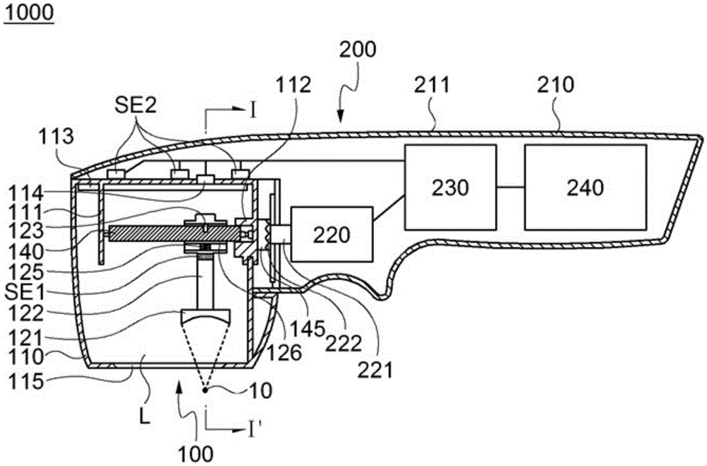
根据本实用新型的实施例的超声波治疗设备1000可以包括盒100和手持件200。在一实施例中,盒100可以可拆卸地结合于手持件200。据此,当在盒100中发生故障时或盒100的寿命终止时,可以更换另一个盒后进行治疗。The
另外,以目的不同的治疗用途而做成的盒100可以可更换地结合于手持件200,从而仅用一个手持件200就可以进行各种治疗。In addition, the
另外,即使具有相同的治疗目的,通过使热焦点10的直径,热焦点10 从皮肤表面隔开的距离等细节特征不同后将设计的盒100可更换地结合于手持件100,从而可以利用具有最适用于治疗特征的热焦点10进行治疗。In addition, even with the same therapeutic purpose, the designed
尽管未图示,手持件和盒不结合成可拆卸而可以制成一体。然而,在这种情况下,优选地,介质填充于从换能器和窗口之间的空间。Although not shown, the handpiece and the case are not combined to be detachable but can be made in one piece. However, in this case, preferably, the medium fills the space between the slave transducer and the window.
在一实施例中,治疗人员可以握住手持件200的一部分后在调节为盒100 接触于治疗对象部位的状态下,以照射聚焦超声波的方式可以进行治疗。为此,手持件200可以设置手柄211。在一实施列中,在构成手持件200的外部盒的手持件外壳210的治疗人员握持的部分是做成人体工程学的形状,由此实现手柄211。In one embodiment, the treatment personnel may hold a part of the
尽管未图示,可以设置用于向治疗人员提供与治疗有关的信息的显示装置,接收治疗人员的指令的输入装置等。Although not shown, a display device for providing treatment-related information to the treatment personnel, an input device for receiving instructions from the treatment personnel, and the like may be provided.
在一个实施例中,在手持件200内部可以设置电源部240。根据本实施例,可以如使用电动剃须刀自由地移动手持件200而进行治疗,从而可以提高便利性。In one embodiment, a
尽管未图示,单独的电缆连接于手持件200后可以在手持件200和其他设备之间提供或接收电力或控制信号。Although not shown, separate cables connected to the
在一实施例中,盒100可以包括盒外壳110、超声波治疗部120、窗口 115和驱动部140。In one embodiment, the
在一实施例中,盒外壳110可以是构成盒100的外壁的一种壳。在盒外壳110内部空间可以设置各种零件,其余空间可以填充介质L。该介质L可以起到将由换能器121发射的聚焦超声波顺利地传递到盒外壳110外部的一种传递媒介的作用。另外,介质L可以起到冷却换能器121生成聚焦超声波过程中产生的热量的作用。In one embodiment, the
在一实施例中,超声波治疗部120可以包括设置于盒外壳110内部且产生聚焦的超声波的换能器121。进而,超声波治疗部120可以包括结合于换能器121的引导部122。此外,超声波治疗部120还可以包括插入针123、引导槽124、弹性构件125、接触板126等。In one embodiment, the ultrasound treatment part 120 may include a
在一实施例中,换能器121产生的聚焦超声波穿过窗口115并传输于盒 100的外部。据此,优选的是,以聚焦超声波穿过时尽可能少受影响的材质和厚度制成窗口115。即,优选的是,使穿过窗口115的聚焦超声波的强度、特征、方向等的变化程度变小。In one embodiment, the focused ultrasound waves generated by
在一实施例中,驱动部140可以执行移动超声波治疗部120的功能。此时,超声波治疗部120可以在盒110内部前进或后退。参照图1,在盒外壳 110将靠近于电机220的部分可以看作是盒外壳110的一端,而将对面可以看作是盒外壳110的另一端。在这情况下,从盒外壳110的一端向另一端的方向移动时,可以看作是前进,反之可以看作是后退。In one embodiment, the driving
在一实施例中,超声波治疗部120的高度可以在前进的同时改变。例如,假设超声波治疗部120发射聚焦超声波的方向是向下方向,则超声波治疗部 120的相对高度可以在盒外壳110内部增加或减少。此外,超声波治疗部120 包括在边前进高度边上升的区间(第一部分;图10的S1)及边前进高度边下降的区间(第二部分;图10的S2)中的至少一个区间以上而移动。In one embodiment, the height of the ultrasound treatment portion 120 may be changed while advancing. For example, assuming that the direction in which the ultrasonic treatment part 120 emits the focused ultrasonic wave is the downward direction, the relative height of the ultrasonic treatment part 120 may be increased or decreased inside the
尽管未图示,在超声波治疗部120后退的同时,超声波治疗部120的高度可以变化。此外,超声波治疗部120的后退的同时高度上升的区间及后退的同时高度下降的区间也可以得到实现。Although not shown, the height of the ultrasonic treatment part 120 may be changed while the ultrasonic treatment part 120 is retreated. In addition, a section in which the height of the ultrasound treatment unit 120 rises while retreating and a section in which the height falls while it retreats can also be realized.
在一实施例中,当超声波治疗部120的高度上升时,换能器121和窗口 115之间的隔开距离可以增加,并且当超声波治疗部120的高度下降时,换能器121和窗口115之间的隔开距离可以减小。In one embodiment, the separation distance between the
在一实施例中,驱动部140可以包括驱动凸轮141。驱动凸轮141可以设置成在盒外壳110内部以规定旋转轴为中心而旋转。在一实施例中,用于固定驱动凸轮141的固定装置可以设置于盒外壳110内侧。如图1所示,第一框架111设置于盒100的另一侧,并且驱动凸轮141的另一端可旋转地结合于第一框架111。In one embodiment, the driving
另一方面,至少部分暴露于盒外壳110的外部的第二旋转部145与驱动凸轮141的一端物理连接,使得驱动凸轮141随着第二旋转部145的旋转而可以旋转。这里,为了不让介质L通过在驱动凸轮141的一端中通过盒外壳 110的部分或在第二旋转部145中通过盒外壳110的部分和盒外壳110之间的间隙而流出可以设置用于确保气密性的密封构件(未图示)。On the other hand, the second
继续参照图1,电机220设置于手持件200,并且与电机驱动轴221连接的第一旋转部222可以将旋转力提供于第二旋转部145。在一实施例中,如图1所示,驱动凸轮141的旋转轴可以与电机驱动轴221平行。在另一实施例中,如图3所示,驱动凸轮141的旋转轴可以与电机220的驱动轴垂直。图1所示的结构可以被称为所谓的枪型(Gun type),并且图3所示的结构可以被称为所谓的杆型(Bar type)。Continuing to refer to FIG. 1 , the
在一实施例中,在图1所示的第三框架113可以设置用于供电或信号线连接的电路板。在电路板设置端子部114,并且端子部114暴露于盒外壳110 的外部,使得手持件200和端子部114电连接。在一实施例中,端子部114 可以连接于手持件200的控制部230。In one embodiment, the
在一实施例中,超声波治疗部120可以可移动地连接于驱动凸轮141。此外,随着驱动凸轮141的旋转,超声波治疗部(120)可以边前进边上升,边前进边下降,边后退边上升,边后退边下降。In one embodiment, the ultrasonic treatment part 120 may be movably connected to the driving
在一实施例中,驱动凸轮141可以形成柱形。此时,驱动凸轮141形成四角柱等多角柱形。此外,在图4中显示驱动凸轮141形成四角柱形的实施例;在图6中显示驱动凸轮141-1形成圆柱形的实施例。In one embodiment, the driving
在一实施例中,在驱动凸轮141的外周面可以设置第一凹槽141h。第一凹槽141h以驱动凸轮141的旋转轴为中心旋转的同时,从驱动凸轮141的一侧到驱动凸轮141的另一侧可以不间断地连接起来。据此,第一凹槽(141h) 可以具有接近螺旋形的轨迹。In one embodiment, a
在一实施例中,引导部122设置插入针123,该插入针123可以插入于第一凹槽141h。在图8中显示插入针123插入于第一凹槽141h后与第一凹槽141h接触的一例。这样,在插入针123和第一凹槽141h接触的点中,最靠近驱动凸轮141的旋转轴的点可以被定义为第一接触点CP1。在附图,显示为插针123的最低点接触于第一凹槽(141h)的最低点,但根据插入针123 和第一槽141h的形状,不是插入针123的最低点或不是第一凹槽141h的最低点的点可以成为第一接触点。In one embodiment, the
根据本实用新型的一实施例,若将第一个接触点CP1的位置连接起来,则可以如图9所示显示出来。即,从第一接触点CP1到驱动凸轮141旋转轴的距离可以增加或减少。此外,第一接触点CP1可以从驱动凸轮旋转轴X1 的一侧开始并前进到驱动凸轮旋转轴X1的另一侧,并且可以以驱动凸轮旋转轴X1为中心而旋转并形成螺旋形。在这种情况下,驱动凸轮旋转轴X1和第一接触点CP1之间的距离也可以增加或减少。According to an embodiment of the present invention, if the positions of the first contact points CP1 are connected, it can be displayed as shown in FIG. 9 . That is, the distance from the first contact point CP1 to the rotational axis of the driving
在一实施例中,若驱动凸轮141旋转,则包括插入针123的超声波治疗部120可以边前进边上升或边前进边下降。In one embodiment, if the
在一实施例中,如图10所示,随着驱动凸轮141的旋转,位于驱动凸轮 141一侧的超声波治疗部120可以边前进边上升。该区间图示为第一区间S1。此外,随着驱动凸轮141的旋转,超声波治疗部120可以边前进边下降,并且该区间图示为第二区间S2。In one embodiment, as shown in FIG. 10 , as the driving
在一实施例中,驱动凸轮141的每次旋转的边前边上升的程度,驱动凸轮141的每次旋转的边后退边下降的程度,通过超声波治疗120生成的热焦点10的直径,在为了确保治疗目的实现及安全性而所需的热焦点10之间的隔开距离和治疗目对象范围的厚度(热焦点10形成所需的组织的厚度)中至少考虑一个数值来可以确定。In one embodiment, the degree to which the
参照图12,在热焦点10应尽可能密集地形成的情况下,在边前进边上升的直线距离热焦点10之间的可允许的最小距离,并且利用安装有设计成使第一区间和第二区间边更换边重复的驱动凸轮141的盒100而可以进行治疗。这里,超声换能器121形成热焦点10的过程可以称为发射(shot),并且第一发射→第一区间移动后第二发射→第二区间移动后第三发射→第一区间移动后第四发射→第二区间移动后以第五区间相同的方式进行治疗,可以使在单位距离内的发射次数最大化,从而密集地形成热焦点10。Referring to FIG. 12 , in the case where the
如图12所示,在对具有相同高度及宽度的治疗对象部位确保安全性的同时,必须尽可能密集地进行发射的治疗中,与以往发射仅是沿直线在一个高度进行的情况相比,在使用根据本实用新型的超声波治疗设备1000的情况下,可以进行更多的发射,从而可以理解为,在确保治疗安全的同时可以提高治疗效率和治疗效果。尽管未图示,但在分别经过第一区间和第二区间的期间,也可以进行2次以上的发射。As shown in FIG. 12 , in the treatment where the radiation must be performed as densely as possible while ensuring the safety of the treatment target site having the same height and width, compared with the conventional case where the radiation is performed only at one height along a straight line, In the case of using the
在一实施例中,若驱动凸轮141旋转,则包括插入针123的超声波治疗部120可以边后退边上升或边后退边下降,由于细节类似于前述,重复的说明不予赘述。In one embodiment, if the
参照图10,在一实施例中,换能器121可以结合于引导部122的下部,并且引导部122的上部可以位于驱动凸轮141的上方。还有,插入针123可以设置于引导部122的上部,并且使其可以面向驱动凸轮141的第一凹槽 141h。在该结构中,插入针123可以通过换能器121和引导部122的重量向第一凹槽141h方向被按压。据此,第一凹槽141h的深度越深插入针123越深地插入于第一凹槽141h,同时超声波治疗部120会下降。此外,治疗对象面不平行于地面而倾斜时,包括窗口115的整个盒100形成倾斜,由此聚焦超声波的照射方向不能与重力方向形成水平而倾斜。在这种情况下,仅通过超声波治疗部120的重量插入针123会不被充分地按压向第一凹槽141h的方向。Referring to FIG. 10 , in one embodiment, the
如上所述,插入针123不能向第一凹槽141h方向充分按压时,在第一凹槽141h内第一接触点CP1的位置会变化,并且根据设计的数值的超声波治疗部120的上升或下降的动作会无法顺利完成。根据本实用新型的实施例的超声波操作设备1000可以包括弹性构件125以解决这样的问题。弹性构件 125执行提供使插入针123向第一凹槽141~1h方向被按压的弹力的功能。这里,如图1及图10等所示,弹性构件125的上端接触于驱动凸轮141的下端,并且使弹性构件125的下端结合于引导部122。据此,引导部122可以向驱动凸轮141的下方被按压,其结果是,设置于引导部122的插入针123会向第一凹槽141h方向被按压。另一方面,根据本实用新型的一实施例的驱动凸轮141是旋转的,但弹性构件125可以通过驱动凸轮141的旋转而发生分离或变形的现象。为了防止这种问题,接触板126可以设置于弹性构件125的上端,并且使接触板126可以接触于驱动凸轮141。As described above, when the
尽管未图示,当插入针123位于驱动凸轮141下方时,弹性构件125的下端接触于驱动凸轮141的上端,并且弹性构件125的上端结合于引导部122,从而还可以提供将引导部122向上方向推的弹力。Although not shown, when the
在一实施例中,在盒外壳110内部可以设置引导轨130。该引导轨130 与引导部122接触的同时,可以起到使引导部122可以稳定地进行前进或后退移动的作用。In one embodiment,
在一实施例中,引导轨130为了平行于驱动凸轮141的旋转轴而可以固定于盒外壳110内部,例如,引导轨130的一端可以结合于第一框架111,并且可以使引导轨130的另一端结合于第二框架112。另一方面,引导轨130 插入的引导槽124可以设置于引导部122。这里,根据本实用新型的实施例的超声波治疗设备1000的超声波治疗部120可以前进或后退的同时上升或下降。还有,引导轨130构平行于驱动凸轮141的旋转轴的直线形状,在这情况下,若引导轨130的上面和导轨130的下面同时接触于引导槽124的同时,引导轨130和引导槽124结合,则引导部122难以上升或下降。据此,在根据本实用新型的一实施例的超声波治疗设备1000,优选地,导轨130的上表面和引导槽124之间的距离可以增大或减小,并且该例显示于图8。尽管未图示,轴承可以设置于导轨130的上面和引导槽124之间,并且可以设置将轴承向引导轨130的方向按压的弹簧等,并且插入针123也可以通过弹簧等向第一凹槽141h的方向被按压。In one embodiment, the
尽管未图示,在一实施例中,在驱动凸轮141表面,也可以代替向驱动凸轮141的旋轴方向凹进去的第一凹槽141而设置从驱动凸轮141的表面向外部的突出的第一突起部。在这情况下,第一突起部可以接触于引导部122 或换能器121,并且在第一突起部与引导部122或换能器121接触的接触点中,最靠近驱动凸轮141的旋转轴的点可以被称为第二接触点。该第二接触点也可以构具有与前述的第一接触点CP1相同的特征。此外,本实施例中,也可以设置弹性构件125,并且弹性构件125可以向换能器121或引导部122 指向第一突起部的方向按压。Although not shown, in one embodiment, the surface of the driving
根据本实用新型的一实施例,可以检测超声波治疗部120的位置。为此,可以应用红外传感器、霍尔传感器、光传感器等各种传感器。例如,如图所示,并且第一传感器SE1可以设置于引导部122。这里,第一传感器SE1可以用红外线传感器实现。此时,在第一传感器SE1由红外线发光部构成的情况下,在对置于第一传感器SE1的位置(例如,第一框架111上的一个地点) 可以设置红外线接收部(未图示)。According to an embodiment of the present invention, the position of the ultrasonic treatment part 120 can be detected. For this purpose, various sensors such as an infrared sensor, a Hall sensor, and a light sensor can be applied. For example, as shown in the drawing, and the first sensor SE1 may be provided to the
另一方面,第一传感器SE1可以包括红外线发射部和接收部来实现。在这情况下,由能够反射红外线的材料制成的反射部可以设置在对置于第一传感器SE1的位置,并且在如图1所示的结构中,反射部(未图示)可以设置于第一框架。On the other hand, the first sensor SE1 may be implemented by including an infrared emitting part and a receiving part. In this case, a reflecting portion made of a material capable of reflecting infrared rays may be provided at a position facing the first sensor SE1, and in the structure shown in FIG. 1, a reflecting portion (not shown) may be provided at a position facing the first sensor SE1. first frame.
在一实施例中,在盒100上方设置用至少一个以上的霍尔传感器或光传感器实现的第二传感器SE2。这里,第二传感器SE2可以设置于手持件200。在这情况下,需要用不妨碍第二传感器SE2检测超声波治疗部120的位置的材料来实现盒外壳110等。例如,当第二传感器SE2用光传感器实现时,优选的是,位于成为位置检测基准的区域和第二传感器SE2之间的盒外壳110 等的构件由具有高透光率的材料而制成。据此,多个盒100可以共用设置于手持件200的第二传感器SE2。在另一实施例中,第二传感器SE2可以设置于盒外壳110内部,但是在这种情况下,具有盒100的制造成本增加的缺点。In one embodiment, a second sensor SE2 implemented with at least one more Hall sensor or light sensor is provided above the
在一实施例中,设置于盒外壳110的传感器可以经由端子部114与控制部230电连接,并且设置于手持件200的传感器可以通过手持件200内部的配线与控制部230电连接。In one embodiment, the sensor provided in the
<实施例二><Example 2>
图13至18是用于说明根据本实用新型的实施例的超声波治疗设备的附图,在下文中,可以省略与第一实施例中描述的内容重复的描述。13 to 18 are drawings for explaining an ultrasonic therapy apparatus according to an embodiment of the present invention, and hereinafter, a description overlapping with that described in the first embodiment may be omitted.
根据本实用新型的实施例的超声波治疗设备2000,可以包括盒2100和手持件200,并且盒2100可以可拆卸地结合于手持件200。在另一实施例中,手持件和盒可以设置为一体而不是设置为可拆卸地结合。The
在一实施例中,盒外壳2110可以是构成盒2100的外壁的一种壳。In one embodiment, the
在一实施例中,超声波治疗部可以包括设置于盒外壳2110内部并产生聚焦超声波的换能器2121。在一实施例中,换能器2121产生的聚焦超声波穿过窗口2115并被传输于盒2100的外部。In one embodiment, the ultrasound treatment part may include a
在一实施例中,驱动部2140可以执行移动超声波治疗部,尤其移动换能器2121的功能。此时,换能器2121在盒外壳2110内部可以前进或后退。In one embodiment, the driving
在一实施例中,换能器2121的高度可以在前进的同时改变。例如,假设从换能器2121发射聚焦超声波的方向是向下方向,则在盒外壳2110内部可以增大或减小换能器2121的相对高度。此外,可以在前进的同时高度上升的区间(第一区间:图18的S1)及前进的同时高度下降的区间(第二区间:图18的S2)中至少包括一个以上区间而可以移动。In one embodiment, the height of the
尽管未图示,但换能器2121后退的同时其高度可以变化。此外,还可以实现换能器2121后退的同时高度上升的区间及后退的同时下降的区间。Although not shown, the height of the
在一实施例中,当换能器2121上升时,换能器2121和窗口2115之间的隔开距离可以增加。此外,当换能器2121下降时,换能器2121和窗口2115 之间的隔开距离可以减小。这里,换能器2121处于最高点时的换能器2121 和窗口2115之间的隔开距离(图18的D1),大于换能器2121处于最低点时的换能器2121和窗口2115之间的隔开距离(图18的D2)。In one embodiment, when the
在一实施例中,驱动部2140可以包括偏心驱动凸轮2141。该偏心驱动凸轮2141可以设置成在盒外壳2110内部以规定的旋转轴为中心而旋转。在一实施例中,偏心驱动凸轮2141可以形成圆柱形,尤其,其旋转轴从圆柱形的中心轴被隔开。在一实施例中,如图16及图17等所示,偏心驱动凸轮2141 可以包括主体2141b和轴2141s。这里,轴2141s的旋转轴可称为轴杆C1,并且主体部2141b的中心轴可称为凸轮轴C2,轴杆C1和凸轮轴C2可以以规定距离彼此平行。In one embodiment, the driving
在一实施例中,偏心驱动凸轮2141的旋转轴可以与杆轴C1相同。即,随着轴2141s以杆轴C1为中心旋转而偏心驱动凸轮2141也可以以杆轴C1 为中心而旋转。此外,随着偏心驱动凸轮2141旋转主体部2141b的凸轮轴 C2也可以以杆轴C1为中心而旋转。In one embodiment, the rotation axis of the
在一实施例中,轴2141s和主体部2141b可以制成一体。在另一实施例中,轴2141s和主体部2141b可以由彼此不同的材料制成。尤其,轴2141s 使用具有高强度的金属等材料制成针状,并且主体部2141b可以使用具有相对低强度但易于实现规定形状或凸凹的合成树脂而实现。据此,偏心驱动凸轮2141的制造效率得到提高的同时,偏心驱动凸轮2141变形的可能性可以降低。另一方面,尽管未图示,在轴2141s形成各种突起部或凹槽部,从而在以压出、注塑、合塑、铸造等多种成型方式成型主体部2141b的过程中,使轴2141s可以作为一种框架结构包括于偏心驱动凸轮2141,从而使由不同材料制成的轴2141s和主体部2141b可以一体化地结合和旋转。In one embodiment, the
在一实施例中,用于固定偏心驱动凸轮2141的固定装置可以设置于盒外壳2110内部。如图13所示,第一框架2111设置于盒2100的另一侧,从而偏心驱动凸轮2141的另一端可旋转地连接于第一框架2111,并且第二框架 2112设置于盒2100的一侧,从而偏心驱动凸轮2141的一端可以以可旋转地结合于第二框架2112。In one embodiment, a fixing device for fixing the
另一方面,至少部分暴露于盒外壳2110外部的第二旋转部2151与偏心驱动凸轮2141的一端物理性地直接或间接地连接并可以使偏心驱动凸轮 2141随着第二旋转部2151的旋转而旋转。这里,所谓“连接”的术语,表示通过规定的媒介连接的意思。在一实施例中,参照图13,以第一齿轮轴2152、第一齿轮2153、第二齿轮2154、第二齿轮轴2155、第三齿轮2156和第四齿轮2157为媒介第二旋转部2151和偏心驱动凸轮2141可以物理连接,由此,第二旋转部2151的旋转运动可以向偏心驱动凸轮2141传递。这种连接结构可以类似地应用于根据图15所示的实施例的超声波治疗设备2000-1。据此,即使当电机220的旋转轴和偏心驱动凸轮2141的旋转轴彼此正交时,也可以有效地传递旋转力。然而,本领域普通技术人员可以理解,齿轮和齿轮轴的数量和布置关系可以根据需要改变。On the other hand, the second
在一实施例中,可以还设置密封构件(未图示)以确保气密性,从而使填充于盒外壳2110的介质L不会流出。In one embodiment, a sealing member (not shown) may be further provided to ensure airtightness, so that the medium L filled in the
继续参照图13,电机220设置于手持件200,并且与电机驱动轴221的连接的第一旋转部件222可以将旋转力提供于前述的第二旋转部件2151。这里,在第一旋转部222和第二旋转部2151的结合设置,第一旋转部222和第二旋转部2151中至少一个可以设置凹凸部223,从而减少在旋转力的传递期间可能发生的损失。Continuing to refer to FIG. 13 , the
在一实施例中,如图13所示,偏心驱动轴2141的旋转轴可以与电机驱动轴221平行。在另一实施例中,如图15所示,偏心驱动凸轮2141的旋转轴可以与电机220驱动轴垂直。In one embodiment, as shown in FIG. 13 , the rotation axis of the
在一实施例中,尽管未图示,用于电源或信号线连接的电路板可以设置于盒2100。使用该电路板可以电连接盒2100和手持件200。In one embodiment, although not shown, a circuit board for power or signal line connection may be provided in the
在一实施例中,超声波治疗部分可以可移动地结合于偏心驱动凸轮2141。此外,随着偏心驱动凸轮2141旋转超声波治疗可以边前进边上升,边前进边下降,边后退边上升,边后退边下降。In one embodiment, the ultrasound treatment portion may be movably coupled to the
在一实施例中,除了换能器2121之外,超声波治疗部还可以包括连接器 2126和连杆2127。此时,连杆2127的一侧结合于偏心驱动凸轮2141,并且连杆2127的另一端连接于连接器2126。还有,连接器2126可以直接或间接连接于换能器2121。In one embodiment, in addition to the
在一实施例中,偏心驱动凸轮2141的外面形成螺纹或螺纹槽并可以与连杆2127的一侧接触。此时,随着偏心驱动凸轮2141旋转而主体部2141b可以以杆轴C1为中心重复上升和下降的同时旋转,但当主体部2141b上升时,连杆2127与主体部2141b一起上升,并且当主体部2141b下降时,连杆2127 可以与主体部2141b一起下降。In one embodiment, the outer surface of the
在一实施例中,连杆2127可以形成环形,并且使主体部2141b可以结合于该环的内部。在一实施例中,环形连杆2127的内侧面和偏心驱动凸轮2141 的外侧面的至少一部分可以螺钉连接。据此,通过偏心驱动凸轮2141的旋转连杆2127前进的同时,可以重复上升和下降。In one embodiment, the
另一方面,连杆2127的另一侧与连接器2126结合,并且连接器2126 可以直接或间接(以规定的元件为媒介)连接于换能器2121。On the other hand, the other side of the
在一实施例中,为了保护换能器2121并与其他元件连接而可以设置换能器外壳2123。还有,连接针2125的一侧和另一侧可以分别结合于换能器外壳2123和连接器2126。In one embodiment, a
超声波治疗设备2000和2000-1还可以包括引导臂2131。在一实施例中,引导臂2131可以执行引导换能器2121等的移动的功能。在一实施例中,在换能器2121前进的同时重复上升和下降的过程中,通过引导臂2131引导换能器2121的移动,从而使从换能器2121照射的超声波的指向方向可以保持恒定,据此,可以提高治疗的安全性和准确性。The
在一实施例中,引导臂2131可以被引导轨2130支撑的同时前进或后退。在一实施例中,引导轨2130为了与偏心驱动凸轮2141的旋转轴(杆轴C1) 平行而可以固定于盒外壳2110内部。例如,引导轨2130的一端结合于第一框架2111,并且引导轨2130的另一端结合于第二框架2112。另一方面,在引导臂2131设置通孔,并且引导臂2131和引导轨2130可以结合,以使引导轨2130穿过通孔。还有,引导轨2130可以形平行于偏心驱动凸轮2141的直线形状。In one embodiment, the
在一实施例中,在引导臂2131可以设置接收前述的连接器2126的空间。此时,连接器2126的外面中至少一部分通过引导臂2131支撑的同时,连接器2126可以上升和下降。为此,连接器2126的形状形成为圆柱或四角柱形,并且在连接器2126收容引导臂2131的部分可以具有对应于连接器2126的形状。In one embodiment, a space for receiving the
在一实施例中,连杆2127的另一侧可以可旋转地结合于连接器2126。连杆2127一侧不仅随着偏心驱动凸轮2141的旋转而上升和下降,而且还可以在垂直于偏心驱动凸轮2141的旋转轴的面上侧方向移动。例如,在连杆 2127形成包裹主体部2141b的环形的情况下,该环的中心和前述凸轮轴C2 可以重叠,并且在偏心驱动凸轮2141旋转时,凸轮轴C2的旋转的同时形成的路径和连杆2127的环中心形成的路径可以相同。这里,即使随着连杆2127 的另一侧可旋转地结合于连接器2126而连杆2127一侧沿着与凸轮轴C2类似的路径移动,连接器2126也可以在被引导臂2131支撑的同时稳定地上升和下降。In one embodiment, the other side of the
在一实施例中,连接针2125的一端结合于换能器外壳2123,并且连接针2125的另一端可以结合于连接器2126。此时,引导臂2131的一部分可以位于换能器外壳2123和连接器2126之间,并且在这种情况下,连接针2125 可以穿过引导臂2131。In one embodiment, one end of the
在一实施例中,还可以设置向换能器2121的上方向突出的引导针2124。该引导针2124以盒外壳2123为媒介可以与换能器2121结合。还有,在引导臂2131可以设置具有与引导针2124对应的形状引导针孔2131h。这里,引导针孔2131h在引导针2124的上升和下降过程中支撑引导针2124,由此换能器2121可以在更稳定地前进的同时重复上升和下降。In one embodiment, a
参照图18,随着偏心驱动凸轮2141旋转位于偏心驱动凸轮2141一侧的换能器2121可以边前进边下降。该区间图示为第一区间S1。此外,换能器 2121随着偏心驱动凸轮2141的旋转而可以边前进边下降,并且该区间被图示为第二区间S2。另一方面,尽管偏心驱动凸轮2141旋转,但用作偏心驱动凸轮2141的旋转中心的杆轴C1仍保持其高度恒定。然而,作为主体部 2141b的中心轴的凸轮轴C2重复随着偏心驱动凸轮2141的旋转定位于最低点C2-L和定位于最高点C2-H的情况。据此,重复换能器2121和窗口2115 之间的距离也在最小值D2和最大值D1之间增大和减小。18 , as the
根据本实用新型的实施例,可以检测换能器2121的位置。为此,可以应用红外传感器、霍尔传感器和光传感器等各种传感器。According to an embodiment of the present invention, the position of the
在一实施例中,如图17所示,并且第三传感器SE3可以设置于在引导臂2131。这里,第三传感器SE3可以用红外线传感器实现。此时,当第三传感器SE3由红外线发射部构成时,在对置于第三传感器(SE3)的位置(例如,第一框架2111上的一个地点)可以设置红外线接收部。In one embodiment, as shown in FIG. 17 , and the third sensor SE3 may be provided at the
在另一实施例中,第三传感器SE3可以包括红外线发射部和接收部而实现。在这情况下,由能够反射红外线的材料制成的反射部可以设置在对置于第三传感器SE3位置,并且在如图3所示的结构中反射部(未图示)可以设置于第一框架(2111)。In another embodiment, the third sensor SE3 may be implemented by including an infrared emitting part and a receiving part. In this case, a reflection part made of a material capable of reflecting infrared rays may be provided at a position opposite to the third sensor SE3, and in the structure shown in FIG. 3, a reflection part (not shown) may be provided at the first Frame (2111).
在一实施例中,在盒2100上方可以设置由至少一个以上霍尔传感器或光传感器实现的第四传感器SE4。这里,第四传感器SE4可以设置于手持件200。在这情况下,必须用不妨碍第四传感器SE4检测超声波治疗部120位置的材料来实现盒外壳2110等。例如,当第四传感器SE4用光传感器实现时,位于成为位置检测基准的区域和第四传感器SE4之间的盒外壳2110的部件等优选地由具有高透光率的材料制成。据此,多个盒2100可以共用设置于手持件200的第四传感器SE4。在另一实施例中,传感器也可以设置于盒外壳2110 内部,但是在这种情况下,具有盒2100的制造成本增加的缺点。In one embodiment, a fourth sensor SE4 implemented by at least one or more Hall sensors or light sensors may be provided above the
本研究作为韩国中小企业厅(the Small and Medium BusinessAdministration,SMBA)技术创新发展项目(Technological Innovation R&D Program)的一环而进行的。[S2459280,开发融合聚焦超声波和影像技术的腋窝多汗症(Primaryaxillary hyperhidrosis)治疗系统]。This research was conducted as part of the Technological Innovation R&D Program of the Small and Medium Business Administration (SMBA) of Korea. [S2459280, development of axillary hyperhidrosis (Primaryaxillary hyperhidrosis) treatment system integrating focused ultrasound and imaging technology].
产业上的可利用性Industrial Availability
根据本实用新型的一实施例的超声波治疗设备可以应用于多汗症治疗、皮肤美容治疗、肥胖治疗等各种治疗,从而可以利用于美容及医疗等领域。The ultrasonic treatment device according to an embodiment of the present invention can be applied to various treatments such as hyperhidrosis treatment, skin beauty treatment, obesity treatment, etc., and thus can be used in the fields of beauty and medical treatment.
Claims (15)
Applications Claiming Priority (5)
| Application Number | Priority Date | Filing Date | Title |
|---|---|---|---|
| KR10-2017-0013457 | 2017-01-31 | ||
| KR1020170013457A KR101756618B1 (en) | 2017-01-31 | 2017-01-31 | Ultrasound operating apparatus |
| KR10-2017-0145131 | 2017-11-02 | ||
| KR1020170145131A KR101893584B1 (en) | 2017-11-02 | 2017-11-02 | Ultrasound operating apparatus |
| PCT/KR2017/013071 WO2018143544A1 (en) | 2017-01-31 | 2017-11-17 | Ultrasonic surgical device |
Publications (1)
| Publication Number | Publication Date |
|---|---|
| CN212166340U true CN212166340U (en) | 2020-12-18 |
Family
ID=63039881
Family Applications (1)
| Application Number | Title | Priority Date | Filing Date |
|---|---|---|---|
| CN201790001581.8U Active CN212166340U (en) | 2017-01-31 | 2017-11-17 | Ultrasound Therapy Equipment |
Country Status (7)
| Country | Link |
|---|---|
| US (1) | US11684808B2 (en) |
| EP (1) | EP3578227B1 (en) |
| JP (1) | JP6931244B2 (en) |
| CN (1) | CN212166340U (en) |
| ES (1) | ES2982019T3 (en) |
| PL (1) | PL3578227T3 (en) |
| WO (1) | WO2018143544A1 (en) |
Cited By (2)
| Publication number | Priority date | Publication date | Assignee | Title |
|---|---|---|---|---|
| CN116669816A (en) * | 2021-01-22 | 2023-08-29 | 杰希思医疗集团株式会社 | Ultrasonic generating device with adjustable ultrasonic focus depth |
| CN119680118A (en) * | 2024-12-16 | 2025-03-25 | 太平洋康泰科学仪器(济南)有限公司 | Ultrasonic induction device |
Families Citing this family (16)
| Publication number | Priority date | Publication date | Assignee | Title |
|---|---|---|---|---|
| KR102165045B1 (en) * | 2020-03-04 | 2020-10-13 | 이가연 | High intensity focused ultrasonic device with vertical assembly structure |
| KR102256560B1 (en) * | 2020-06-11 | 2021-05-27 | 주식회사 제이시스메디칼 | Ultrasonic generator with adjustable ultrasonic focusing depth |
| KR102521030B1 (en) * | 2020-09-09 | 2023-04-12 | 주식회사 제이시스메디칼 | Ultrasonic medical cartridge and ultrasound medical device including the same |
| KR102522627B1 (en) * | 2020-09-17 | 2023-04-17 | 주식회사 제이시스메디칼 | Ultrasonic medical instrument with adjusable focusing depth of ultrasonic wave generator |
| KR102554437B1 (en) | 2020-12-07 | 2023-07-12 | 주식회사 제이시스메디칼 | Ultrasonic medical cartridge and ultrasound medical device including the same |
| CN116568370A (en) * | 2020-12-11 | 2023-08-08 | 维奥尔株式会社 | Ultrasonic device with reciprocating motion transfer transducer |
| IL303546A (en) * | 2020-12-11 | 2023-08-01 | Viol Co Ltd | Ultrasound apparatus with reciprocating transfer way of transducer |
| EP4260904A4 (en) * | 2020-12-11 | 2024-12-18 | ViOL Co., Ltd. | ULTRASONIC DEVICE WITH DOUBLE DISPLACEMENT TYPE TRANSDUCER |
| IL307960A (en) * | 2021-04-26 | 2023-12-01 | Jeisys Medical Inc | Apparatus and method for controlling movement of ultrasonic wave generating unit |
| KR102588217B1 (en) * | 2021-05-13 | 2023-10-12 | 주식회사 제이시스메디칼 | Ultrasonic generator with adjustment of ultrasonic focusing depth |
| KR102590648B1 (en) * | 2021-05-13 | 2023-10-18 | 주식회사 제이시스메디칼 | Ultrasound generator with adjustable ultrasonic focusing depth |
| KR102514207B1 (en) * | 2021-12-28 | 2023-03-27 | 권오석 | Cartridge for moving focal point of ultrasound and treatment device using ultrasound comprising the same |
| CN115154253B (en) * | 2022-09-08 | 2022-11-08 | 苏州好博医疗器械股份有限公司 | Ultrasonic treatment head with automatic moving function |
| KR102889087B1 (en) * | 2023-03-27 | 2025-11-20 | 주식회사 노바메디 | Ultrasound generating apparatus |
| KR102938203B1 (en) * | 2023-05-02 | 2026-03-12 | 주식회사 루트로닉 | Catridge for high intensity focused ultrasound apparatus and apparatus including the same |
| KR20250143533A (en) * | 2024-03-25 | 2025-10-02 | 텐텍 주식회사 | Ultrasonic generating device having position recognition function of ultrasonic generator |
Family Cites Families (15)
| Publication number | Priority date | Publication date | Assignee | Title |
|---|---|---|---|---|
| JPS5668443A (en) * | 1979-11-12 | 1981-06-09 | Olympus Optical Co | Ultrasonic scanner for inspecting body cavity |
| JPH0576538A (en) * | 1991-09-13 | 1993-03-30 | Shimadzu Corp | Ultrasonic treating device |
| US5443068A (en) * | 1994-09-26 | 1995-08-22 | General Electric Company | Mechanical positioner for magnetic resonance guided ultrasound therapy |
| WO2002081025A1 (en) * | 2001-04-06 | 2002-10-17 | Mattioli Engineering Ltd. | Apparatus for skin absorption enhancement |
| US20070062290A1 (en) * | 2005-08-30 | 2007-03-22 | Ultrasonic Technologies Ltd. | Motor driven mechanism for mechanically scanned ultrasound transducers |
| US8409102B2 (en) | 2010-08-31 | 2013-04-02 | General Electric Company | Multi-focus ultrasound system and method |
| KR101191347B1 (en) | 2010-10-20 | 2012-10-15 | (주)클래시스 | 3-dimension movable handpiece for high intensive focused ultrasound apparatus |
| US9510802B2 (en) * | 2012-09-21 | 2016-12-06 | Guided Therapy Systems, Llc | Reflective ultrasound technology for dermatological treatments |
| KR20140067482A (en) * | 2012-11-26 | 2014-06-05 | 주식회사 유니온 메디칼 | Handpiece |
| KR101623528B1 (en) * | 2014-04-04 | 2016-05-23 | 이성근 | An ultrasound handpiece which the forward - backward and high - low control are possible |
| JP2015204894A (en) * | 2014-04-17 | 2015-11-19 | オリンパス株式会社 | Medical ultrasound device |
| KR101637519B1 (en) * | 2014-11-26 | 2016-07-07 | 주식회사 로보맥스 | An ultrasound handpiece |
| KR101822539B1 (en) * | 2015-02-25 | 2018-03-08 | 주식회사 아띠베뷰티 | Ultrasound apparatus |
| US10856842B2 (en) * | 2014-11-26 | 2020-12-08 | Attibe Beauty Co., Ltd. | Ultrasonic wave generating device and procedure method using the same |
| KR101756618B1 (en) | 2017-01-31 | 2017-07-10 | 박종철 | Ultrasound operating apparatus |
-
2017
- 2017-11-17 US US16/480,179 patent/US11684808B2/en active Active
- 2017-11-17 EP EP17895385.7A patent/EP3578227B1/en active Active
- 2017-11-17 PL PL17895385.7T patent/PL3578227T3/en unknown
- 2017-11-17 WO PCT/KR2017/013071 patent/WO2018143544A1/en not_active Ceased
- 2017-11-17 CN CN201790001581.8U patent/CN212166340U/en active Active
- 2017-11-17 ES ES17895385T patent/ES2982019T3/en active Active
- 2017-11-17 JP JP2019538475A patent/JP6931244B2/en active Active
Cited By (2)
| Publication number | Priority date | Publication date | Assignee | Title |
|---|---|---|---|---|
| CN116669816A (en) * | 2021-01-22 | 2023-08-29 | 杰希思医疗集团株式会社 | Ultrasonic generating device with adjustable ultrasonic focus depth |
| CN119680118A (en) * | 2024-12-16 | 2025-03-25 | 太平洋康泰科学仪器(济南)有限公司 | Ultrasonic induction device |
Also Published As
| Publication number | Publication date |
|---|---|
| PL3578227T3 (en) | 2024-09-23 |
| US11684808B2 (en) | 2023-06-27 |
| JP2020505116A (en) | 2020-02-20 |
| ES2982019T3 (en) | 2024-10-14 |
| US20190366129A1 (en) | 2019-12-05 |
| JP6931244B2 (en) | 2021-09-01 |
| EP3578227B1 (en) | 2024-05-29 |
| EP3578227A1 (en) | 2019-12-11 |
| EP3578227A4 (en) | 2020-01-22 |
| WO2018143544A1 (en) | 2018-08-09 |
| EP3578227C0 (en) | 2024-05-29 |
Similar Documents
| Publication | Publication Date | Title |
|---|---|---|
| CN212166340U (en) | Ultrasound Therapy Equipment | |
| KR101756618B1 (en) | Ultrasound operating apparatus | |
| KR101893584B1 (en) | Ultrasound operating apparatus | |
| JP7254375B2 (en) | Ultrasonic generator capable of adjusting focal depth of ultrasonic waves and obesity treatment method | |
| US12605568B2 (en) | High-intensity focused ultrasound device and method for controlling transducer moving piezoelectric device used in the same | |
| KR102094444B1 (en) | Ultrasound operating apparatus | |
| KR101822539B1 (en) | Ultrasound apparatus | |
| JP2018500075A (en) | Ultrasonic generator and treatment method using the same | |
| KR102118017B1 (en) | Piezo-electric driving device and high intensity focused ultrasound(hifu) handpiece device using the same | |
| KR20230051447A (en) | Ultrasonic medical cartridge and ultrasound medical device including the same | |
| JP2024519489A (en) | An ultrasonic generator that allows you to adjust the ultrasonic focusing depth | |
| KR20240005613A (en) | Ultrasonic medical catridge and controlling metohd thereof | |
| HK30074363A2 (en) | Ultrasonic surgical device | |
| KR102889087B1 (en) | Ultrasound generating apparatus | |
| CN115737815B (en) | A magnetically controlled micro-nanoparticle device with positioning/treatment functions | |
| CN116712674A (en) | Intelligent automatic basin bottom treatment device and control method thereof | |
| KR101750015B1 (en) | Ultrasound apparatus | |
| CN115103655A (en) | Treatment device comprising a tool holder and a tool with a contact rotary motion device | |
| CN221535476U (en) | Ultrasonic therapy handpiece and ultrasonic therapy device | |
| KR101779604B1 (en) | Cradle of medical device for operating | |
| KR20230077214A (en) | Ultrasonic handpiece device |
Legal Events
| Date | Code | Title | Description |
|---|---|---|---|
| GR01 | Patent grant | ||
| GR01 | Patent grant |