CN212162233U - Auxiliary device for fixing power plug - Google Patents
Auxiliary device for fixing power plug Download PDFInfo
- Publication number
- CN212162233U CN212162233U CN202021369800.8U CN202021369800U CN212162233U CN 212162233 U CN212162233 U CN 212162233U CN 202021369800 U CN202021369800 U CN 202021369800U CN 212162233 U CN212162233 U CN 212162233U
- Authority
- CN
- China
- Prior art keywords
- fixed
- fixedly connected
- power plug
- screw
- screw rod
- Prior art date
- Legal status (The legal status is an assumption and is not a legal conclusion. Google has not performed a legal analysis and makes no representation as to the accuracy of the status listed.)
- Active
Links
Images


Landscapes
- Details Of Connecting Devices For Male And Female Coupling (AREA)
Abstract
The utility model discloses a fixed auxiliary device of power plug, including socket shell, socket shell's anterior fixedly connected with support, the fixed case of bottom fixedly connected with of support, the inside of fixed case is equipped with the dwang, the surface of dwang rotates and is connected with the fixed plate, fixed plate and socket shell inner wall fixed connection, the equal fixedly connected with screw rod in both ends of dwang, two sets of screw rods are relative distribution, the surface threaded connection of screw rod has the screwed pipe, the top fixed connection gag lever post of screwed pipe, the top fixed connection clamping components of gag lever post, the bar hole site has been seted up to the upper surface of fixed case, the tip fixedly connected with knob of screw rod. The utility model has the advantages that: the plug can be clamped by the two groups of clamping assemblies by rotating the knob, so that the connection between the plug and the socket is more stable, the support is more attractive when the clamping assemblies are protected, and the support is stably and firmly connected with the socket shell and can be detached.
Description
Technical Field
The utility model relates to a fixed auxiliary device specifically is a fixed auxiliary device of power plug belongs to power plug technical field.
Background
The power plug refers to a device for connecting devices such as electrical appliances to a power supply, and generally, the plug is inserted into a socket so as to be communicated with the power supply, and the phosphor copper sheet in the socket has good elasticity, so that the power plug can conduct electricity and provide enough clamping force, and the plug is not easy to fall off naturally.
Although the inside phosphorus copper sheet of socket can press from both sides tight plug, some install in outdoor socket, for example the socket that is used for the electric motor car to charge in the big-arch shelter, may lead to the phosphorus copper sheet to relax after using for a long time, reduce the centre gripping effect of plug, when meetting strong wind weather, strong wind blows the plug and rocks, may lead to the plug to drop, unsatisfied user demand.
SUMMERY OF THE UTILITY MODEL
The utility model aims at providing a fixed auxiliary device of power plug just in order to solve above-mentioned problem, can make two sets of clamping components be close to each other through rotating the knob and press from both sides tightly the plug, make being connected between plug and the socket more stable, be difficult to drop.
The utility model discloses a technical scheme realizes above-mentioned purpose, a power plug fixes auxiliary device, including socket shell, socket shell's anterior fixedly connected with support, the bottom fixedly connected with fixed case of support, the inside of fixed case is equipped with the dwang, the surface of dwang rotates and is connected with the fixed plate, fixed plate and socket shell inner wall fixed connection, the both ends of dwang are all fixedly connected with screw rod, two sets of screw rod are relative distribution, the surface screw thread of screw rod is connected with the screwed pipe, the top fixed connection gag lever post of screwed pipe, the top fixed connection clamping components of gag lever post, the upper surface of fixed case has seted up the bar hole site, the tip fixed connection knob of screw rod;
the clamping component comprises a fixed block, a sliding rod, a spring and a limiting block, the fixed block is fixedly connected to the top of the limiting rod, the sliding rod is fixedly connected to one side surface of the sliding block, the spring is movably sleeved on the outer portion of the sliding rod, the sliding rod is movably sleeved with the fixed block, and the limiting block is fixedly connected to the end portion of the sliding rod.
Preferably, the bracket is fixedly connected to the upper surface of the fixed box, and the clamping assembly is located inside the bracket.
Preferably, one end of the spring abuts against the sliding block, the other end of the spring abuts against the fixed block, and the spring is in a contraction state.
Preferably, two first round holes are seted up on one side surface of fixed block, the sliding block cup joints with the activity of first round hole.
Preferably, the bar hole site is located the top of screw rod, gag lever post slip joint is inside the bar hole site.
Preferably, the outer side of the support is fixedly connected with a plurality of connecting blocks, a second round hole is formed in the front surface of each connecting block, a locking bolt is movably inserted into each second round hole, a screw hole is formed in the front surface of the socket shell, and the locking bolt is in threaded connection with the screw hole.
Preferably, the knob is located outside the fixed box, a third round hole is formed in the surface, close to the knob, of one side of the fixed box, the screw penetrates through the third round hole to be fixedly connected with the knob, and the screw is rotatably connected with the third round hole.
The utility model has the advantages that: the power plug fixing auxiliary device is provided with a rotating rod, a fixing plate, a screw rod, a spiral tube, a limiting rod, clamping components and a knob, the two groups of clamping components can be close to each other to clamp a plug by rotating the knob, a spring extrudes a sliding block, and the two groups of sliding blocks which are distributed oppositely simultaneously clamp the plug, so that the connection between the plug and a socket is more stable, and the probability that the plug is separated from the socket due to external factors such as strong wind blowing is reduced;
this fixed auxiliary device of power plug is equipped with support, connecting block and locking bolt, clamping component is located the inside of support, prevents that clamping component from exposing outside, and is more pleasing to the eye when protecting clamping component, and support and fixed case are firm with socket shell's stable connection to can dismantle, conveniently overhaul simple structure, the simple operation satisfies the user demand with fixed case.
Drawings
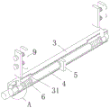
Fig. 1 is a schematic view of the overall structure of the present invention;
fig. 2 is a schematic view of a connection structure between the socket housing and the bracket according to the present invention;
FIG. 3 is a cross-sectional view of the fixing box of the present invention;
fig. 4 is an enlarged view of a point a in fig. 3 according to the present invention;
fig. 5 is a schematic view of the clamping assembly of the present invention.
In the figure: 1. socket shell, 101, screw, 2, support, 3, fixed case, 31, bar hole site, 4, dwang, 5, fixed plate, 6, screw rod, 7, solenoid, 8, gag lever post, 9, clamping component, 91, fixed block, 92, sliding block, 93, slide bar, 94, spring, 95, stopper, 10, knob, 11, connecting block, 12, locking bolt.
Detailed Description
The technical solutions in the embodiments of the present invention will be described clearly and completely with reference to the accompanying drawings in the embodiments of the present invention, and it is obvious that the described embodiments are only some embodiments of the present invention, not all embodiments. Based on the embodiments in the present invention, all other embodiments obtained by a person skilled in the art without creative work belong to the protection scope of the present invention.
Referring to fig. 1-5, an auxiliary device for fixing a power plug includes a socket housing 1, a bracket 2 is fixedly connected to the front portion of the socket housing 1, a fixing box 3 is fixedly connected to the bottom of the bracket 2, a rotating rod 4 is arranged inside the fixing box 3, a fixing plate 5 is rotatably connected to the outer surface of the rotating rod 4, the fixing plate 5 is fixedly connected to the inner wall of the socket housing 1, two ends of the rotating rod 4 are fixedly connected with screws 6, the two groups of screws 6 are distributed oppositely, a screw tube 7 is connected to the outer surface of the screw tube 6 through a thread, a limiting rod 8 is fixedly connected to the top of the screw tube 7, a clamping assembly 9 is fixedly connected to the top of the limiting rod 8, a strip-shaped hole site 31 is formed on the upper surface of the fixing;
clamping assembly 9 includes fixed block 91, sliding block 92, slide bar 93, spring 94 and stopper 95, and fixed block 91 fixed connection is at the top of gag lever post 8, and slide bar 93 fixed connection is in a side surface of sliding block 92, and the outside at slide bar 93 is cup jointed in the spring 94 activity, and slide bar 93 cup joints with fixed block 91 activity, and stopper 95 fixed connection is at the tip of slide bar 93.
As a technical optimization scheme of the utility model, 2 fixed connection of support are at the upper surface of fixed case 3, and clamping unit 9 is located the inside of support 2, prevents that clamping unit 9 from exposing outside, and is more pleasing to the eye when protecting support 2.
As the utility model discloses a technical optimization scheme, the one end of spring 94 offsets with sliding block 92, and the other end of spring 94 offsets with fixed block 91, and spring 94 is the contraction status, and after sliding block 92 touched with the plug, fixed block 91 continued to be close to the plug, extrudeed spring 94, made spring 94 take place elastic deformation, and spring 94 extrudees sliding block 92 because elastic deformation will the reconversion.
As a technical optimization scheme, two first round holes have been seted up to a side surface of fixed block 91, and sliding block 92 cup joints with first round hole activity, and two sets of sliding blocks 92 activity respectively cup joints in two first round holes, carries on spacingly to sliding block 92, makes sliding block 92 can not rotate at will.
As a technical optimization scheme, bar hole site 31 is located the top of screw rod 6, and 8 slip joints of gag lever post are inside bar hole site 31, and gag lever post 8 is spacing to make screwed pipe 7 unrotatable by bar hole site 31 to screw rod 6 can drive screwed pipe 7 when rotating and slide at the surface of screw rod 6.
As the utility model discloses a technical optimization scheme, a plurality of connecting blocks 11 of outside fixedly connected with of support 2, the second round hole has been seted up on the front portion surface of connecting block 11, the activity is pegged graft in the second round hole has locking bolt 12, screw 101 has been seted up on the front portion surface of socket shell 1, locking bolt 12 and screw 101 threaded connection, make support 2 and fixed box 3 and socket shell 1's firm in connection to can dismantle, conveniently overhaul with fixed box 3.
As a technical optimization scheme of the utility model, knob 10 is located the outside of fixed case 3, and fixed case 3 has been close to a side surface of knob 10 and has been seted up the third round hole, and screw rod 6 passes third round hole and knob 10 fixed connection, and screw rod 6 rotates with the third round hole to be connected, can make two sets of clamping component 9 be close to each other through rotating knob 10 and carry out the centre gripping to the plug.
When the utility model is used, after a plug is inserted into a socket, the knob 10 is rotated to drive the two groups of screw rods 6 to rotate, the screw tube 7 is in threaded connection with the screw rods 6, the limiting rod 8 is limited by the strip hole sites 31 to prevent the screw tube 7 from rotating, so that the screw rods 6 can drive the screw tubes 7 to slide on the outer surfaces of the screw rods 6 when rotating, the screw threads are in opposite directions due to the relative distribution of the two groups of screw rods 6, the two groups of screw tubes 7 can be close to or away from each other by rotating the knob 10, the clamping components 9 are fixedly connected with the screw tubes 7 through the limiting rod 8, and then the two groups of clamping components 9 can be driven to be close to or away from each other, the two groups of clamping components 9 are close to each other by rotating the knob 10 to clamp the plug, after the fixing block 91 is contacted with the plug, the, spring 94 will restore to the original state because elastic deformation extrudes sliding block 92, and two sets of sliding block 92 that distribute relatively press from both sides tight the plug simultaneously, make the connection between plug and the socket more stable, reduced the plug because external factors such as strong wind blows the probability that breaks away from with the socket.
For those skilled in the art, the two sets of clamping assemblies 9 can be moved close to each other by rotating the knob 10 to clamp the plug, so that the connection between the plug and the socket is more stable and is not easy to fall off.
Furthermore, it should be understood that although the present description refers to embodiments, not every embodiment may contain only a single embodiment, and such description is for clarity only, and those skilled in the art should integrate the description, and the embodiments may be combined as appropriate to form other embodiments understood by those skilled in the art.
Claims (7)
1. An auxiliary device is fixed to power plug, includes socket shell (1), its characterized in that: the front part of the socket shell (1) is fixedly connected with a bracket (2), the bottom of the bracket (2) is fixedly connected with a fixed box (3), a rotating rod (4) is arranged in the fixed box (3), the outer surface of the rotating rod (4) is rotatably connected with a fixed plate (5), the fixed plate (5) is fixedly connected with the inner wall of the socket shell (1), both ends of the rotating rod (4) are fixedly connected with screw rods (6), the two groups of screw rods (6) are distributed oppositely, the outer surface of the screw rod (6) is in threaded connection with a solenoid (7), the top of the solenoid (7) is fixedly connected with a limiting rod (8), the top of the limiting rod (8) is fixedly connected with a clamping assembly (9), the upper surface of the fixed box (3) is provided with a strip-shaped hole site (31), and the end part of the screw rod (6) is fixedly connected with a knob (10);
clamping assembly (9) includes fixed block (91), sliding block (92), slide bar (93), spring (94) and stopper (95), fixed block (91) fixed connection is at the top of gag lever post (8), slide bar (93) fixed connection is at a side surface of sliding block (92), spring (94) activity cup joints the outside at slide bar (93), slide bar (93) cup joint with fixed block (91) activity, stopper (95) fixed connection is at the tip of slide bar (93).
2. A power plug attachment accessory as claimed in claim 1, wherein: support (2) fixed connection is at the upper surface of fixed case (3), clamping component (9) are located the inside of support (2).
3. A power plug attachment accessory as claimed in claim 1, wherein: one end of the spring (94) is abutted against the sliding block (92), the other end of the spring (94) is abutted against the fixed block (91), and the spring (94) is in a contracted state.
4. A power plug attachment accessory as claimed in claim 1, wherein: two first round holes have been seted up to one side surface of fixed block (91), sliding block (92) cup joint with first round hole activity.
5. A power plug attachment accessory as claimed in claim 1, wherein: the bar hole site (31) are located the top of screw rod (6), gag lever post (8) slip joint is inside bar hole site (31).
6. A power plug attachment accessory as claimed in claim 1, wherein: the socket is characterized in that a plurality of connecting blocks (11) are fixedly connected to the outer side of the support (2), a second round hole is formed in the front surface of each connecting block (11), a locking bolt (12) is movably inserted into each second round hole, a screw hole (101) is formed in the front surface of the socket shell (1), and the locking bolt (12) is in threaded connection with the screw hole (101).
7. A power plug attachment accessory as claimed in claim 1, wherein: the rotary knob (10) is located on the outer side of the fixed box (3), a third round hole is formed in the surface, close to the rotary knob (10), of one side of the fixed box (3), the screw rod (6) penetrates through the third round hole to be fixedly connected with the rotary knob (10), and the screw rod (6) is rotatably connected with the third round hole.
Priority Applications (1)
| Application Number | Priority Date | Filing Date | Title |
|---|---|---|---|
| CN202021369800.8U CN212162233U (en) | 2020-07-13 | 2020-07-13 | Auxiliary device for fixing power plug |
Applications Claiming Priority (1)
| Application Number | Priority Date | Filing Date | Title |
|---|---|---|---|
| CN202021369800.8U CN212162233U (en) | 2020-07-13 | 2020-07-13 | Auxiliary device for fixing power plug |
Publications (1)
| Publication Number | Publication Date |
|---|---|
| CN212162233U true CN212162233U (en) | 2020-12-15 |
Family
ID=73700246
Family Applications (1)
| Application Number | Title | Priority Date | Filing Date |
|---|---|---|---|
| CN202021369800.8U Active CN212162233U (en) | 2020-07-13 | 2020-07-13 | Auxiliary device for fixing power plug |
Country Status (1)
| Country | Link |
|---|---|
| CN (1) | CN212162233U (en) |
-
2020
- 2020-07-13 CN CN202021369800.8U patent/CN212162233U/en active Active
Similar Documents
| Publication | Publication Date | Title |
|---|---|---|
| CN102496789A (en) | Angle-adjustable combined ground rod | |
| CN212162233U (en) | Auxiliary device for fixing power plug | |
| CN209200306U (en) | A kind of solar energy cable confluence connector | |
| CN207818931U (en) | A kind of quick wire connector | |
| CN213278437U (en) | Two-way butt-joint waterproof connector | |
| CN114421232A (en) | Wire and frame integral type connector | |
| CN208723214U (en) | A kind of fast plug of photovoltaic cable | |
| CN201623448U (en) | Quick connecting box of film solar cell assembly | |
| CN204905459U (en) | Safe portable earth bar | |
| CN208460855U (en) | A kind of gathering line pluggable connecting device | |
| CN220797297U (en) | Connector for interconnecting and installing portable photovoltaic modules | |
| CN221553215U (en) | Photovoltaic module junction box | |
| CN220402085U (en) | Anti-falling power supply device | |
| CN109861013B (en) | Temporary grounding clamp for power transmission line tower | |
| CN221080826U (en) | Wire guide for cable access and distribution box | |
| CN221283147U (en) | Junction box assembly | |
| CN209982397U (en) | Solar photovoltaic power generation assembly and solar power generation curtain wall | |
| CN218770956U (en) | Cable threading device for weak current wiring | |
| CN215378350U (en) | Wiring device for electric power engineering design construction | |
| CN209626558U (en) | A kind of shockproof connector of circle locking of wind power generation | |
| CN213584203U (en) | Grounding wire device with LED illumination function | |
| CN219610825U (en) | Large-current connector capable of being flexibly matched | |
| CN218334739U (en) | Direct-connected low-voltage inflatable switch cabinet bus switching device | |
| CN218456190U (en) | Rotary clamping structure of power adapter | |
| CN221767266U (en) | Wind-powered electricity generation cable connector dismounting device |
Legal Events
| Date | Code | Title | Description |
|---|---|---|---|
| GR01 | Patent grant | ||
| GR01 | Patent grant |